1. S N
UCRL-ID-129096-98
High-Power Laser Source Evaluation
C. A. Back, C. D. Decker, J. F. Davis, S. Dixit, J. Grim, R. A. Managan,
F. J. D. Serduke, G. F. Simonson, L. J. Suter, C. R. Wuest, F. Ze
July 1998
"?Sfei
This is an informal report intended primarily for internal or limited external
distribution. The opinions and conclusions stated are those of the author and may or
may not be those of the Laboratory.
Work performed under the auspices of the U.S. Department of Energy by the
Lawrence Livermore National Laboratory under Contract W-7405-ENG-48.
fy;
DISTRIBUTION STATEMENT A
fiCff p? of Mb
Approved for Public Release
Distribution Unlimited
jraCQUALmriH8PECHBD4 CvQ TU/i1 ^ - O ? ~ |4~|<ä
2. DISCLAIMER
This document was prepared as an account of work sponsored by an agency of the United States Government. Neither the United States Government
nor the University of California nor any of their employees, makes any warranty, express or implied, or assumes any legal liability or responsibility for
the accuracy, completeness, or usefulness of any information, apparatus, product, or process disclosed, or represents that its use would not infringe
privately owned rights. Reference herein to any specific commercial product, process, or service by trade name, trademark, manufacturer, or
otherwise, does not necessarily constitute or imply its endorsement, recommendation, or favoring by the United States Government or the University of
California. The views and opinions of authors expressed herein do not necessarily state or reflect those of the United States Government or the
University of California, and shall not be used for advertising or product endorsement purposes.
This report has been reproduced
directly from the best available copy.
Available to DOE and DOE contractors from the
Office of Scientific and Technical Information
P.O. Box 62, Oak Ridge, TN 37831
Prices available from (615) 576-8401, FTS 626-8401
Available to the public from the
National Technical Information Service
U.S. Department of Commerce
5285 Port Royal Rd.,
Springfield, VA 22161
3. NWET ANNUAL REPORT QDV-99-0001
t^SJ-i.'.-f-A-,
Lawrence Bivermore Ifationap^flööratory
l§*f Livefmore, CalirAfnia JPM50
High-PoweBLaser Soutee Evaluation
Christina A. Bac% Christopher D. Decke1| John-F. Davis*,
Sham ^Öixit, Jariob Grun+, Robert A. Managan,
Franklin J. D^Serdul^e, Gregory F., Simonson,
Laurance^I. Suterf Craig R. Wuest, and Fred Ze
July, 11998
J
•^
ia
■ SI
%?"
Final Report oryJACROs 9Fr3022 and 97-3048
^f..;,,.^ tO
Mr. Richard Gullickson
Dr. Ralph Schneider
Defense Special Weapons Agency
*Alme and Associates
f
Naval Research Laboratory
for more information, please contact
Franklin Serduke
LLNL L-183
* Livermore, CA 94550
1(925)422-6592
DSWA Final Report
4. NWET ANNUAL REPORT QDV-99-0001
TABLE OF CONTENTS
I- INTRODUCTION AND OVERVIEW
II- EXPERIMENTAL MEASUREMENTS OF X-RAY EMISSION FROM XENON-
FILLED BERYLLIUM HOHLRAUMS 6
II-l. INTRODUCTION: 6
II-2. EXPERIMENTAL SETUP: 6
II-3. EXPERIMENTAL RESULTS 7
1-4. CONCLUSIONS 14
III- LASNEX MODELING OF UNDERDENSE PLASMA RADIATORS 15
III-l. INTRODUCTION 15
III-2. DISCUSSION 15
III-3. CONCLUSIONS: 19
IV- HOT X-RAY OUTPUT FROM SEED-LAYER IGNITION CAPSULES 20
IV-1. INTRODUCTION 20
IV-2. THE CAPSULE 21
IV-3. THE LASER DRIVE 21
IV-4. CALCULATIONAL PROCEDURE 21
IV-5. WHERE IS THE EMISSION OCCURRING? 22
IV-6. SEEDING STRATEGIES 23
1. SEEDING THE DT FUEL 23
2. SEEDING THE ABLATOR 24
3. SEED LAYER BETWEEN THE FUEL AND ABLATOR 25
IV-7. RESULTS FROM THIN SEED LAYERS 25
1-8. CONDITIONS IN THE SEED LAYER 27
1-9. CONCLUSIONS 27
1-10. REFERENCES 30
V- REVIEW AND STATUS OF FACILITIZATION FOR NWET ON NIF 31
V-L REQUESTED MODIFICATIONS IN THE NIF DESIGN 31
1-2. STATUS OF THE REQUESTED NIF DESIGN MODIFICATIONS 31
1-3. LASER SYSTEM 32
1-4. DESIGN CHANGES THAT AFFECT NWET FACILITIZATION 32
1-5. PULSE STACKING, LONG PULSE SHAPES 33
1-6. ico/2co OPERATIONS: SUPRATHERMAL ELECTRON BREMSSTRAHLUNG 33
1-7. loo OPERATION 34
1-8. THE 2fo OPTION 34
1-9. POTENTIAL TEST SCENARIOS 35
1-10. DISTRIBUTED SOURCES 35
1. DIFFRACTIVE OPTICS 35
2. APERTURES IN THE PAMS 36
1-11. TARGET AREA 37
DSWA Final Report - 2
5. NWET ANNUAL REPORT QDV-99-0001
VI- DISTRIBUTED SOURCE ARRAY DESIGN 39
39
VI-1. DESIGN OBJECTIVES
VI-2. X-RAY SOURCE LASER ENERGY, POWER & TARGETING REQUIREMENTS 40
1. SOURCES WITH PHOTON ENERGIES 1 -5 KEV 41
2. SOURCES WITH PHOTON ENERGIES 5-15 KEV 41
3. GREATER THAN 25 KEV SOURCES 42
42
1-3. ARRAY DESIGN STATUS
1-4. DIFFRACTIVE OPTICS / FRESNEL LENS DEVELOPMENT 44
VII- NIF CONSTRUCTION. STARTUP. AND NRSUG PLANS 45
45
VH-l. CONSTRUCTION
45
VII-2. STARTUP
VII-3. PLANS 46
VIII- NON-IGNITION X-RAY SOURCE FLUENCE-AREA PRODUCTS FOR
NUCLEAR WEAPONS EFFECTS TESTING ON NIF 49
VIII-1. INTRODUCTION 49
VIII-2. COMPONENTS OF THE FLUENCE X AREA PRODUCT FORMULA 49
49
1. USABLE NIF ENERGY, ENIF:
5
2. SOURCE EFFICIENCY PER STERADIAN, X: °
5
3. DEBRIS SHIELD TRANSMISSION, T: •
5
4. SOLID ANGLE, AQ, FOR+10% UNIFORMITY: '
VIII-3. ESTIMATED FLUENCE X AREA PRODUCTS: 51
52
VIII-4. REFERENCES
DSWA Final Report - 3
6. NWET ANNUAL REPORT QDV-99-0001
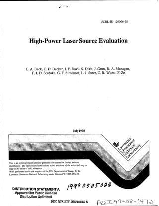
l-lntroduction and Overview
Robust Nuclear-Weapons-Effects Testing (NWET) capability will be needed for the
foreseeable future to ensure the performance and reliability, in nuclear environments, of the
evolving U.S. stockpile of weapons and other assets. Ongoing research on the use of
high-energy lasers to generate environments of utility in nuclear weapon radiation effects
simulations is addressed in the work described in this report. Laser-driven hohlraums and a
variety of other targets have been considered in an effort to develop NWET capability of the
highest possible fidelity in above-ground experiments. The envelope of large-system test
needs is shown as the gray region in fig. 1. It does not represent the spectrum of any
device; it is just the envelope of the spectral region of outputs from a number of possible
devices. It is a goal of our laser-only and ignition-capsule source development work to
generate x rays that fall somewhere in this envelope. One of the earlier appearances of this
envelope is in ref. 1.
The Defense Special Weapons Agency provided important support for the work described
herein. A total of $520K was provided in the 1997 lACROs 97-3022 for Source
Development and 97-3048 for Facilitization. The period of performance specified in the
Statement of Work ran from 28 February 1997 until 30 November 1997. This period was
extended, by agreement with DSWA, for two reasons: 1) despite the stated period of
Disk Targets & Underdense Radiators / Hot e- bremsstrahlung
NIF Target Outputs
based on
Envelope >f Large
Nova Experiments
System Tt st Needs
and
Lasnex modeling
Estimate of "SLIC"
NIF ignition capsule
NWET performance
Assumptions
• Uniformity
0-15keV±10%
>15keV±33%
• Efficiency
0-2 keV 50%
1-5 keV 25%
5-15keV10%
>15keV0.25%
1000
Photon Energy (keV)
Figure l: Plot of the uniform fluence-area products of various NIF non-ignition sources plus an estimate of
the performance of the Seed-Layer Ignition Capsule against a background of the envelope of large-system
test requirements suggested by Dr. Cyrus P. Knowles of Jaycor.
DSWA Final Report
7. NWET ANNUAL REPORT QDV-99-0001
performance, funds were not available at LLNL to begin this work until somewhat later in
the fiscal year, and 2) we agreed to stretch the current resources until follow-on funds were
in hand, to minimize effects of ramping down and up again.
The tasks addressed in this report are the following:
1) Non-ignition-source model benchmarking and design. This involves analysis of
existing and new data on laser-only sources to benchmark LASNEX predictions
2) Non-ignition-source development experiments
3) Ignition capsule design to improve total x-ray output and simplify target fabrication
4) Facilitization of source arrays and of the NIF for NWET
A funding triad that includes the Defense Special Weapons Agency, the NIF Project and
LLNL's Defense Technology Department supports the work that is reported in this
document. The additional work presented here shows how the DSWA-funded work
integrates with the larger effort.
There has been continued success in the development and fielding of the potentially longer-
duration non-ignition beryllium-can sources. There have been advances in understanding of
the relevant physics of these underdense radiators as well as further experimental support
for the validity of the predictions. This report includes results on our SLIC designs (Seed
Layer Ignition Capsules) that permit optimism for prospects of improving the hot-x-ray-to-
neutron ratio and total hot x-ray yield for NIF ignition targets.
An important summary of the laser-only x-ray environments appears again in this year's
document. This summary serves as an audit trail for the non-ignition-sources that are
projected for NIF based on experimental results and on projections of LASNEX modeling.
Reference:
1. NWET Applications for NIF Workshop (a compendium of viewgraphs)
15-17 March 1994. ed. by Gregory Simonson of LLNL
DSWA Final Report
8. NWET ANNUAL REPORT QDV-99-0001
ll-Experimental Measurements of X-Ray Emission from
Xenon-filled Beryllium Hohlraums
11-1. Introduction:
As a follow-on to experiments in 1996, three xenon-gas-filled beryllium hohlraum shots
were performed in July 1997. These shots were on hohlraums that were redesigned based
on post-shot calculations of the previous targets (see next article). The targets were
improved by using larger laser entrance holes (LEHs) to eliminate refraction of the laser
beam that was caused by low density Be plasma that formed at the inside edges of the
LEHs. A small percentage of krypton (Z=36) gas was added to the xenon (Z=54) to
attempt a measurement of the plasma temperature using ratios of various x-ray lines from
helium-like krypton. Target diagnostics showed uniform heating of a 2 mm long gas-filled
can and an x-ray pulse that was longer in duration. The peak of the x-ray emission and x-
ray pulse duration are more consistent with the predictions from simulations. The
conversion efficiency measured by the absolutely-calibrated spectrometer was similar to
previous determinations, approximately 12 % for the 2 mm diameter hohlraums.
11-2. Experimental Setup:
As before, experiments were performed using the NOVA laser. Due to newly lowered Nova
beam energy constraints, we used approximately 32 kJ of 0.35 jim laser light in 2 ns flat-
topped intensity profile. The 1996 shots had about 40 kJ available. This operational
energy limit was lowered due to damage to laser optics. The laser beams entered through
the holes in the endcaps of the target and irradiated the inside of a Be cylinder that was
filled with xenon gas and a 10%-20% admixture of krypton for temperature diagnostics.
The lasers heat the gas to form a highly ionized plasma that emits x-rays. These x-rays
pass through the walls of the Be cylinder and are detected by both time-resolved and time-
integrated diagnostics. The physical target dimensions were similar to previous shots - 1.8
mm outer length (1.6 mm inner length) and 2 mm in diameter; however, in this design the
laser entrance holes (LEHs) were 1.5 mm in diameter instead of 1.0 mm. Detailed post-
shot calculations of the 1.0 mm LEHs of the target indicated that the x-ray pulse and
heating were negatively affected by refraction of the laser beams by a low density Be
plasma that formed at the edges of the entrance holes. For the current experiments, the
LEHs were increased from 1 mm to 1.5 mm in diameter to eliminate the problem and to test
this aspect of the calculations. Furthermore, one Be hohlraum was increased to 3.6 mm in
diameter to test a scaling of the conversion efficiency with size of the target. The gas fill in
the targets was slightly modified from the previous targets in that Xe was doped with 10%
or 20% Kr to enable measurements of temperature by K-shell spectroscopy of the almost-
fully-ionized krypton. In all other target fabrication respects, i.e., glue, pressure tests, Be
wall thickness, etc., the targets were similar to the previous series of experiments.
The diagnostic complement was enhanced by the addition of more x-ray diodes and x-ray
film packs. Previously-used diagnostics were fielded again and included absolutely-
calibrated x-ray crystal spectrometers called Henways, x-ray streak cameras, and x-ray
imagers. New diagnostics were x-ray diodes that gave an independent second
measurement of the conversion efficiency and x-ray film packs which measured the angular
symmetry of the x-ray emission.
DSWA Final Report - 6 -
9. NWET ANNUAL REPORT QDV-99-0001
o 2.5 r
(D
(Q
fi>
X
<
O
>_
(0
■D
0) 3"
.c
a
(0
(A
>
>
- 4.0 4.5 5.0 5.5 6.0 6.5 7.0 7.5
photon energy (keV)
Figure I. Spectrum from a time-integrated x-ray spectrometer. This target was a filled to 1 atm with
80% Xe and 20% Kr. It was 1.8 mm in length and 2.0- mm in diameter. The ordinates of this plot are
uncertain due to difficulties with the absolute calibration of the instrumentation. The left axis shows
the x-ray intensity. The right axis shows the cumulative integral of this x-ray intensity.
11-3. Experimental Results
Three shots were performed in this series of experiments in 1997. All were on 1 atm
targets. One was filled with 80% Xe and 20% Kr and two were filled with 90% Xe and
10% Kr. These Xe-filled hohlraum targets were irradiated by the Nova laser to investigate
the x-ray output of laser-heated targets in the photon energy range of 4 to 10 keV. Two
targets with a 2 mm diameter were fielded - one with 80% Xe and 20 % Kr, and the other
with 90 % Xe and 10 % Kr. The third target was 3.6 mm in diameter with a 90% Xe and
10 % Kr gas fill. The Nova laser delivered 32 kJ of laser energy in a 2 ns flat-topped laser
pulse that supersonically ionizes the Xe gas. Target shot numbers were 27072309,
27072311, and 27072403 (large can).
Conversion efficiency was measured by both the Henway crystal spectrometers as before,
and with x-ray diodes brought from NRL. In fig. 1 is an example of the spectrum and its
running integral from shot 27072309. The running integral is plotted on the right-hand
axis. The n= 3-2 transitions are found in the 4-to-5 keV range and the n=4-2 and 5-2
transitions are in the 5.5-to-7 keV range. For each shot, these data are collected for two
positions, one from the side and the other along the axis of the hohlraum. The x-ray output
from these small hohlraums were not angularly dependent, in contrast to previous shots
with smaller laser entrance holes. The large hohlraum, however, did show a slight
asymmetry. The two shots performed on the 2 mm diameter (small) hohlraums gave a
conversion efficiency of 15% into the 4 to 7.5 keV photon energy range. The larger
hohlraums were less efficient and gave a conversion efficiency of 9.4% from the side and
13.0% along the laser axis. This larger hohlraum was filled to the same pressure and
therefore density, however, they were less efficient which is consistent with x-ray images
of the hohlraum that showed that the entire volume of gas was not uniformly heated.
DSWA Final Report 7 -
10. NWET ANNUAL REPORT QDV-99-0001
Measurements by the x-ray diodes tend to give a lower conversion efficiency, near 7%.
However, the analysis of these data was hampered by a low signal-to-noise ratio, which
makes the error bar large. While this conversion efficiency is still much larger than ablative
disk targets in this regime, the difference between the two conversion efficiency
measurements by the Henway Bragg crystal spectrometers and the x-ray diodes fielded on
the same shot is under investigation. Both of these measurements depend on the absolute
calibration of the diagnostics. In the case of the spectrometer, the reflectivity of the crystal
is the largest error, and this can easily account for a 50 % error bar. For the diodes, this
depends on the calibration of the anodes on a source of measured flux.
10 mm
;p mm
Blocking Hal» Porittonw
-^
._ ?5 mm ■
^I2 mm p rl
^^fvitlons fe £ I
Main Tube (57 mm I.D.)
Manson Source
fcCP-CCD "=PE
S7.07mm t At (whin Ml 9? mmn
's
Crystal "R"
Crystal "G
Figure 2a. Schematic of experimental setup designed by Fred Ze to measure integrated reflectivity of the
curved Henway crystals used in the experiments. A Manson source and microchannel plate were used to
record the data
tV£jftVtjjft
HgtUnft ye HgpyQA , Hpn1PAYiHerj2gg Jj^n)pgysHgn?Pfi, ■Hqn.1 RC vs Hangrjr,
s —■— 10000 r —
-500 0 500 -500 O 500
Space ^m)
Figure 2b. Measurement of the integrated reflectivity of a curved Henway crystal used in the experiments.
The top curve indicates the incident x-rays source intensity, the bottom curve is a measure of the
reflectivity corrected for the microchannel plate response.
DSWA Final Report 8 -
11. NWET ANNUAL REPORT QDV-99-0001
For the crystals, we have performed measurements on a stationary-anode source in the
laboratory. This does not measure the rocking curve of the crystal, however, it does
measure the integrated reflectivity. Figure 2 shows some results from supplementary
measurements on a laboratory Manson x-ray source that we are continuing to analyze.
The angular dependence was examined by the use of x-ray film packs that were located at
two different points within the chamber. They were passive diagnostics that were attached
to diagnostic-insertion SIM carts that were driven into the chamber for the gated and
streaked diagnostics. These film packs were filtered for both above 4 keV photon energies,
and also for above 13 keV photon energies and were time integrated. The results showed
a less-than 5 % asymmetry.
The temporal dependence of the Xe emission (hv = 4-7 keV) was only obtained on the
large hohlraum. In the first two shots, time-dependent data were not obtained due to
diagnostic difficulties. The large hohlraum shows marked improvement in conversion
efficiency compared to the targets shot in 1996 due to the improved design of the
hohlraum. Figure 3 shows the temporal history of the emission compared to the data from
the 1996 series. The red curve is from the 1997 data while the blue and green curves are
from the 1996 data. In the 1997 data, the emission lasts for nearly the full 2 ns duration of
the laser pulse whereas before, the refraction of the beam at the laser entrance holes caused
a reduced emission after 1 ns.
to
c
0)
Time (ns)
Figure 3. Temporal history of the x-ray pulse of the L-shell of Xe. The red curve is the large-can new
data showing a longer duration of the x-rays of interest. The green curve is for the old design 1996
target with a smaller LEH and a 1 atm fill and the blue curve is for the 1996 target with a 2 atm fill.
Imaging results showed a vast improvement in the uniformity of the heated target. They
are recorded on a gated pinhole imager and filtered for appropriate photon energy ranges.
For the smaller 2 mm diameter targets, the x-ray emission is fairly uniform in the side-on
images. This is in contrast to the previous target design (experiments in 1996) that showed
a central cold region, even late in time. Figure 4 shows x-ray images of the target from the
side view filtered for two different photon energy bands. The lasers enter the hohlraum
DSWA Final Report
12. NWET ANNUAL REPORT QDV-99-0001
'*?S-Ä*
Xe image @ 1.3 ns (hv > 4 keV) Kr image @ 1.3 ns (hv > 13 keV)
Figure 4. Two-dimensional x-ray images of the target. The image of the left is for photon energies
> 4 keV and is dominated by the Xe emission at 1.3 ns . The image on the right is filtered for
photon energies > 13 keV: At 1.3 ns these come primarily from Kr in the target.
from the left and right of the target. On the left is an image filtered for x-rays at 4 keV and
above. Here it is fairly uniform in the second half of the pulse and some plasma is seen
escaping the laser entrance holes. On the right is an x-ray images filtered for hv > 13 keV.
A two lobed emission pattern is still visible early in time, but at about 1.5 ns, it remains
non-uniform even later in the pulse. The data show that the lasers have already propagated
into the center of the hohlraum by 1 ns for Xe (hv>4 keV images) and by 1.3 ns in the Kr
(/zv>13 keV images). This x-ray emission is strongly weighted by the density and we are
presently comparing these images with computer simulations of the target.
A variation in Xe emission over this region at
a later time, ~ 1.8 ns, was measured to be
-10 % on shot 27072311 and this has a high
correlation with the laser energy on target.
In the case shown below in figure 5, the
energy of the laser beams irradiating the top
of the target was slightly lower. In the
future, beam balance can be requested to
avoid this non-uniformity.
The larger targets still show small volumes
of gas that are not heated enough to emit >4
keV x-rays. Figure 6 gives an example of
these images to compare to those in figure 3,
Xe image @ 1.8 ns (hv > 4 keV) but for the larger target. We currently
comparing these images with calculations of
Figure 5. X-ray image for a 1 atm pressure the emission.
target at photon energies hv> 4 keV. The entire
inner volume 2 mm in diameter and 1.8 mm Images taken end-on from the axial pinhole
long is recorded in emission at a time 1.8 ns after imager are shown for the small and large
the laser starts. hohlraum in figure 7. The blue and red
circles show the diameter of the two different
sized cans viewed end-on. The smaller
DSWA Final Report 10
13. NWET ANNUAL REPORT QDV-99-0001
Large hohlraum Xe image (>4 keV)@ 1.8 ns Kr image (>13 keV)@ 1.8 ns
Figure 6. X-ray image for a I atm pressure target at photon energies hv > 4 keV at 1.8 ns into
the pulse for a 3.6 mm diameter target. In the Xe image, the larger volume is not uniform and the
corners of the target are not heated sufficiently to emit > 4 keV x-rays. In the Kr image, the
emission is in the center and does not spread to the full diameter of the can.
diameter target images show bright emission at the wall of the 2 mm diameter can which
corresponds to the positions of the incoming beams on the inside wall of the hohlraum.
The brighter emission at the wall is of considerable interest since the wall is made of Be and
should not emit more than the gas fill at these photon energies. The Be wall material is
provided by Brush Wellman and the material certification shows that this material consists
2 mm diameter 3.6 mm diameter
Figure 7. X-ray images from gated axial pinhole cameras filtered for x-rays > 4keV at about 1 ns
into the experiment.. The left image is from a 2 mm diameter hohlraum and the right image is
from the 3.6 mm larger diameter hohlraum.
DSWA Final Report
14. NWET ANNUAL REPORT QDV-99-0001
of 99.39 % Be. (P.O. # 1448403), where the contaminants are largely low to mid-Z
materials. The highest Z contaminant is Ti at 0.004 % which is a small enough percentage
to have a negligible effect on the emission, even if Ti He a lines at 4.7 keV are produced.
Independent target characterization on site at LLNL of the actual target shows impurities of
O, Al, Si, S, Cl, K, Ca and Fe in small quantities that total less than 0.1 % by weight.
Again this confirms that the impurities are insufficient to cause significant amounts of
emission in these target images. Thus, the higher emission observed is probably an effect
due to the higher density of the gas near at the wall since the Be is expected to ablate
towards the center of the hohlraum and compress the Xe plasma.
In the 3.6 mm diameter hohlraum this compression effect is not visible and instead
"columns" of heated gas are produced where the laser beam passes. The intensity of the
emission in these images is not the same as those in the side-on view because of different
gains in the x-ray framing cameras.
During these experiments, there was also an attempt to measure the krypton K-shell lines
that can serve as a temperature diagnostic. The geometry is shown below in figure 8. The
FigureS. Schematic of the target chamber showing the SIM tube geometry fielded for the temperature
sensitive diagnostic. The outside circle represents the 2.2 meter radius Nova target chamber. The blue
line is the line of sight of the SIM lube tilted low by 3 ° and the red line shows the x-ray path. The
light blue line is the position of the crystal.
DSWA Final Report 12
15. NWET ANNUAL REPORT QDV-99-0001
diagnostic was an x-ray streak camera coupled to a Bragg crystal. The krypton He-a line
is at 13.1 keV; high-resolution spectroscopy at this photon energy has not been done before
at Nova. We need to get high resolution in order to use the ratio of the Li-like satellite lines
to the He-a line as a temperature diagnostic. As this ratio becomes larger, the temperature
is lower because more Li-like satellite lines exist at lower temperatures.
Experimentally two different crystals were fielded. The sensitivity to these high energy x-
rays is not well measured because they are not commonly used and stationary x-ray
calibration sources have difficulty achieving these photon energies. In figure 8, the
outside circle is a schematic of the 2.2 meter radius target vacuum chamber and the SIM
tube is explicitly shown coming up from the bottom left. Due to the Bragg angle needed
for sufficient resolution, the spectrometer was pointed below target chamber center to
accommodate a quartz (5052) or a LiF (422) Bragg crystal; these have a 2d spacing of
1.624 and 1.652 Ä respectively. Ge (111) was considered but not used because of
possible fluorescence of the Ge itself at these energies. Alignment of the diagnostic was
tested on a maintenance day at Nova and offsets for the SIM tube were calibrated at that
time.
FILE "27072309ssc3.pds" Horizontal line-out
ROWS #333 TO 476 Y FROM 19.9200 TO 28.5000 AY (EDGES) =8.64000
T"
X(irm)
Figure 9. Spectrum from two different shots, taken at 1.5 ns. The peak at x = 7 mm is due to
krypton He-a emission at 13.1 keV
An example of the data obtained on this instrument is shown in figure 9. A streaked x-ray
spectrometer shows a pronounced double bump in time in the Xe/Kr continuum emission
with the Kr He-a line appearing in the second half of the 2 ns pulse on the first target.
Below are a preliminary spectral lineouts showing the data from two different shots. The
peak is due to emission from the He-a line located on the abscissa at approximately x=7
mm is at 13.1 keV. The emission is weaker than expected and therefore the determination
of temperature from this data is difficult due to low signal-to-noise ratio.
DSWA Final Report - 13
16. NWET ANNUAL REPORT QDV-99-0001
11-4. Conclusions
Experimental measurements have been performed on laser-produced plasmas that show
they can generate a significant quantity of x-rays above 4 keV. In summary, these targets
show that the design of the hohlraums is much improved from the previous experiments.
This improvement is principally due to the larger laser entrance hole size, which eliminates
refraction of the incoming laser beams. We are continuing to analyze the data. The results
show a conversion efficiency similar to the 1996 targets, but a much more uniform heating
of the target. The large-scale computer simulations for conversion efficiency and duration
of the x-ray pulse better model these data. For a Xe filled hohlraum volume of 5 mm3, we
are able to produce a 7-13 % efficient underdense radiator. The larger hohlraums are both
predicted and measured to have about 25% lower x-ray conversion efficiency. There are
three-dimensional features in the data that should be studied in further modeling.
Side-on imaging of the targets indicates we successfully produced targets with the entire
length of the hohlraum to be in emission. The uniformity was measured to be -10 % that
can be entirely attributed to beam balance and this can be improved with better balance of
the beam energies in future targets.
End-on imaging of the small cans that shows higher-intensity radiation near the walls
under the laser spots suggests that there may be a tamping of the emitting gas by blowoff of
the beryllium hohlraum material. By contrast, the large hohlraum emission appeared to be
along the laser beams and did not achieve early or mid-time higher-intensity radiation near
the walls. However the sideways extent of the columns of radiation seen in the large
hohlraums could give clues of electron conductivity in these plasmas.
New filter pack diagnostics and corrections to the original data based on the relative
calibrations have reduced the apparent asymmetry of the previous data to within
uncertainties of the measurements.
Outstanding issues include the x-ray crystal and diode calibrations to reduce the error bar
and inconsistencies in the conversion efficiency numbers. The conversion efficiency
ranged from 5% to 20%, depending on the angle of view.
First attempts at a K-shell krypton temperature diagnostic were encouraging but
inconclusive. These photon energies (> 13 keV) have not been measured on Nova laser-
produced plasmas before and the small number of shots makes diagnostic development
difficult. The krypton He-a line was observed, but the signal level is quite low. Two-
dimensional images of the targets show the region of emission for Kr {hv>.3 keV) is
smaller than for Xe (hv>4 keV). This diagnostic is still being developed.
DSWA Final Report - 14
17. NWET ANNUAL REPORT QDV-99-0001
lll-Lasnex Modeling of Underdense Plasma Radiators
IH-1. Introduction
Underdense plasma radiators have been studied as part of a program to produce multi-keV
x-ray sources for use on large lasers such as NIF. The initial work in this area focussed on
xenon-filled gas bags that were driven by the Nova laser. More recently, it has been
proposed to use laser-heated Xe-filled Be hohlraums or cans; these sources are predicted to
have a high conversion efficiency and an x-ray output duration longer than those from
laser-heated gas bags. As a result, experiments were executed to assess the performance of
these underdense radiators and to test our ability to model them.
4 101 i I i i i i I ) i i i | i i i i | i i i i
Experiment
3 10 12 Simulation
P(TW)
2 10 12
1 10 12
U »III! I ■ I . I I I I ■ I I I I ■ I I I I I 4 I I I *"
0 0.5 1 1.5 2 2.5 3
t(ns)
Figure 1. Comparison of the 1996 underdense plasma temporal emission profile with two simulations:
one with refraction of the incoming laser beams, the other without. It is very suggestive that refraction
was truncating the x-ray emission and is the basis for the increased laser-entrance hole diameter in the
1997 shots described in the previous article.
111-2. Discussion
In this report we present simulations that were performed after the first set of gas-filled-can
experiments. These simulations help to understand the differences between modeling and
the experimental results as well as to aid in designing the next round of experiments.
Simulations and experiment were not in full accord following the first round of beryllium-
can experiments. The duration of the emission lasted only about 1 ns in contrast to the
DSWA Final Report 15 -
18. NWET ANNUAL REPORT QDV-99-0001
:
«&v..-
":^i|s -
■.**§£
Figure 2. Lasnex modeling of the largc-(l.5 mm diameter) laser-entrance-hole beryllium hohlraum
that is filled with 1 atmosphere of xenon gas. In practice, only one quadrant of this picture is
modeled because of symmetry. The laser beams are shown in magenta, the Be hohlraum in black and
the interface between the beryllium blowoff and the xenon gas is shown in cyan. This shows that the
larger LEH has solved the late-time beam refraction problem. Tick marks are separated by 100 (im.
predicted 2 ns. The experimental images also showed spatial gaps in the emission patterns,
whereas simulations indicated that the emission should not show a gap at the center. A
series of simulations was performed which attempted to mock up effects such as inhibited
electron transport, beam deflection and backscattering. None of these effects appeared to
recover the experimental results.
However, the experimental emission images indicated that large amounts of plasma had
escaped the can through the laser entrance hole (LEH). In the first set of Lasnex
simulations, material outside the Be can was lost from the calculation during rezones. After
modifying our zoning scheme to follow the escaping plasma properly, we found that Be
blow-off from the lip of the laser entrance hole was impinging into the path of the laser
beam. This near critical density plasma was found to refract the laser beam so severely
that the beam would no longer enter into the can. With refraction included we found that the
temporal history of the x-ray emission agreed well with experiments. To show this we plot
in figure 1 the experimental results (red) along with the initial simulations (blue) and the
new simulations (green) including refraction.
As a result of the simulations which included Be blow-off, modifications to the Be can
design were made which alleviated the refraction problem. In particular, the laser entrance
hole diameter was increased from 1.0 mm to 1.5 mm. The dimensions of the new design
are shown in figure 2 where we plot the can zoning (black), the laser rays (magenta), and
DSWA Final Report - 16
19. NWET ANNUAL REPORT QDV-99-0001
x-ray production
111111 M11111 ii 111111111111
New design
0
t(ns)
Figure 3. Predicted temporal history of the x-ray emissions from the old, small LEH design and the
new, large LEH design.
the interface between the Be and Xe (cyan). This figure shows that the Be blowoff
material does not impinge on the path of the laser beam.
The temporal history of the x-ray power from the new design is shown in figure 3 along
with that from the old design. At early time the x-ray production is a bit less for the new
design due to less confinement of the gas with the larger LEH. However, the x-ray
production increases with time and last for the full 2 ns. The time integrated x-ray
production is greatly improved with the new design.
The new LEH designs were the basis of the next set of experiments that were reported in
the previous article. These experiments had two targets sizes both with the larger LEH
t(ns)
Figure 4. Comparison of the LASNEX predictions with the measured xenon L-shell emission for
the large (3.6 mm diameter) can.
DSWA Final Report 17 -
20. NWET ANNUAL REPORT QDV-99-0001
Figure 5. Side view of a beryllium Hohlraum with X-ray images showing radiation with hv > 4 keV.
:
The upper row shows the data. The lower row shows synthetic images produced by postprocessing the
Lasnex simulation.
shown in figure 2. The standard size can (2 mm long x 2 mm diameter) was used along
with a larger can (2 mm long x 3.6 mm diameter). The targets produced uniform emission
lasting the entire duration of the laser pulse as predicted. In figure 4 we plot the x-ray
emission versus time for the large can along with the predictions. The temporal history of
the x-ray emission agrees quite well with the experiments. Therefore, we now believe the
refraction hypothesis to be the probable cause for the discrepancies seen in the first
campaign.
In Figure 5 we plot the observed spatial images of the x-ray emission as well as the
emission patterns predicted by simulations. Before making comparisons it is important to
note that the data no longer show the dark gaps at the center at early time. The can appears
to be uniformly heated and the resulting emission pattern is uniform for the duration of the
laser pulse. This is a vast improvement over the first set of experiments. This fact along
with the temporal data indicates that refraction from the LEH was indeed degrading the
performance of the first targets.
However, the simulations differ from the data in two distinct ways. First, the simulations
predict brighter emission at the center plane. Whereas, the data seems to be more or less
uniform over the can. Second, the simulations predict a tamping effect in which the ablating
Be squeezes the Xe gas radially inward. The predicted x-ray emission patterns therefore get
narrower with time as shown in Figure 5. In contrast, the experimental images appear to
have the same height throughout the laser pulse.
In order to comment on the possible source of these discrepancies we must first understand
why the simulated emission patterns appear as they do. In a coronal approximation, we can
assume that the emission per unit volume scales like the electron density squared multiplied
by some power (usually 1/2) of the electron temperature. The emission pattern can be
understood by taking this scaling for the local emission and transporting the x-rays out of
the can allowing for rotational symmetry. Therefore, in figure 6. we plot the electron
temperature and the electron density at 2.0 ns. We can see that the emission at the center is
DSWA Final Report - 18
21. NWET ANNUAL REPORT QDV-99-0001
due to the stagnation shown in Figure 6. Even though there is no stagnation on axis, the
rotational symmetry makes the emission appear to occur on axis.
The stagnation may be a two dimensional effect. In two-dimensional cylindrically
symmetric simulations the laser spots are rings uniform around the azimuth. Therefore, the
blow-off plasma is also symmetric and must converge like a cylinder. On Nova, there are
five laser spots on each side of the hohlraum; the space between spots is initially
comparable to the spot size itself. Thus, in the experiments in three dimensions, the plasma
blow off occurs in different regions and may not accumulate in the same manner.
Electron Temperature Electron Density
:
p* |g?
0.00 1.00 2.00 3.00 4.00 5.00 0.0 0.5 1.0
T,e (keV) ne/nc
Figure 6. Lasnex images of the electron temperature in keV and electron density in units of the fraction
of the critical electron density for 0.35 micron laser light, These quantities are shown for a small (radius
= 2 mm) beryllium hohlraum at 2 ns. just as the laser drive beams are turning off.
Likewise the fact that the data shows no tamping may also be a three dimensional effect.
With a five beams in the azimuth there are regions where there is little tamping. Therefore,
the x-rays can still come from larger radii and would show very little tamping.
These discrepancies may be resolved by diagnosing the electron density and electron
temperature in several regions throughout the can. In addition, three dimensional
simulations would also be very useful to see how the plasma really might stagnate.
111-3. Conclusions:
Lasnex modeling has led to the design of a successful underdense radiating beryllium
hohlraum filled with an L-shell xenon plasma. This correct problem was identified after
examining several parameters related to the Lasnex simulations. The temporal profile of the
simulations and of the measured data for the large hohlraum are in very reasonable accord.
Diagnostic difficulties during the experiment prevent comparison with the emission from
the smaller-radius hohlraums. There remain some qualitative and quantitative differences
between the measurements and experiments. In particular, we are interested in the apparent
fact that the hottest, most strongly radiating portions of the plasma in the small hohlraums,
even relatively early in the laser pulse, appear near the walls of the hohlraum. This may be
due to 3-dimensional effects. These are important questions to address.
DSWA Final Report 19 -
22. NWET ANNUAL REPORT QDV-99-0001
IV-Hot X-Ray Output from Seed-Layer Ignition Capsules
Hot x-rays are needed for radiation effects testing on NIF. Based on LASNEX
calculations, we find that it may be possible to make hot-x-ray-source ignition capsules.
Two new NIF ignition capsule designs are presented. Both designs eliminate the need to
seed the frozen DT. The first design adds a mid-Z seed to the ablator. The second design
puts a thin layer of the seed material between the DT fuel and the ablator. This has very
positive implications for target fabrication. Unoptimized results suggest that a 30 MJ
ignition capsule can produce over 5MJ of x-rays above 5 keV, about 2 MJ have energies
above 20 keV, and about 1 MJ are above 40 keV. We have also found that many useful x-
rays are lost to absorption in standard gold hohlraum walls; alternate hohlraum designs
with much less gold and lower-Z walls are being investigated.
IV-1. Introduction
We have looked at ways to increase the hot x-ray output by the modification of
successful designs of NIF ignition capsules (ref. I) This is of interest to the radiation
effects community. There is an ongoing need to revalidate hardware by exposing it to
fluences of x-rays above 10 keV. Without underground testing NIF will be one of very few
sources able to provide the
needed fluences of these x-
rays.
The result is a new variant of
the standard NIF ignition
capsule (ref. 1) that is
illustrated schematically in fig.
1. This design holds promise
for more flexibility in tailoring
output, producing more
copious and harder x-rays. In
addition, the target fabrication
challenge is reduced from that Baseline Hi-Z-seeded CHO-Br SLIC
of earlier designs that relied with Frozen DT ablator Seed Layer
on seeding the frozen DT, to CHOBr changed to Ignition Capsule:
1-2 micron
be nearly identical to that of a ablator CHO-Seed seed layer
"standard" NIF ignition ablator outside Frozen DT
capsule. However, Figure 1. Schematic diagrams of the ignition capsules discussed in
considerable research remains this section. The ablator material in most of our calculations is
to be done on many physics brominated plastic (CHO-Br for short and color-coded green in these
issues. diagrams). The indicated radii are approximate. The first capsule is the
We have also begun work on baseline that has been designed by Steve Haan of LLNL's X division
a modified hohlraum design. and his collaborators. The remaining capsules indicate the seed
This design uses lower-Z material in red. The second capsule has high-Z seed material mixed
materials since a standard gold into the outer third of the frozen DT (this design presents a target
hohlraum severely attenuates fabrication challenge). In the third capsule, the bromine in the ablator
the x-rays of interest (10-30 is replaced with a selected seed material. The fourth capsule shows the
keV). This redesigned SLIC design, which stands for Seed Layer Ignition Capsule. So far,
hohlraum must have same we have modeled only very thin, mid-Z seed layers. If hydrodynamic
performance as the "standard" performance would be improved by adding a density gradient in a
hohlraum. We have identified thicker seed layer, we could be compelled to move in that direction.
the problem and are beginning
work on a number of ideas.
DSWA Final Report 20
23. NWET ANNUAL REPORT QDV-99-0001
IV-2. The Capsule
Our capsule designs are based on designs by
Steve Haan, Max Tabak, and Tom Dittrich of radius (mm)
X Division. Our work was started on a 30
MJ capsule using a brominated plastic ablator
(the first capsule in fig. 1); we are also using
a 17 MJ capsule that has a copper doped
beryllium (CuBe) ablator in our LASNEX
calculations. The design variations evolved
through three phases as shown in fig. 1. The
first variation put a high-Z seed in the outer CHO + 0.25%Br or
third of the DT fuel. The second variation Be+ 1%Cu Ablator
replaced the bromine in the ablator with a
mid-Z material. The third variation put a thin
(~2 |im) layer of a mid-Z seed between the
DT fuel and the ablator. Our best results
have been obtained with the SLIC design ~ 2 urn thick mid-Z
shown in fig. 2 using a molybdenum K- K-shell radiating seed layer
shell- radiating seed layer between DT & ablator
IV-3. The Laser Drive
Figure 2. This pie diagram shows the structure of the
The laser pulse is shaped to produce a brominated plastic ablator capsule.
sequence of shocks that converge on the DT
shell. The time-dependent drive spectrum,
when converted to temperature, is shown in
fig. 3. Designers adjust the time and
magnitude of the various steps in the drive
pulse to optimize shock convergence and
0.30 -
capsule performance >
IV-4. Calculations! Procedure t
a 0.20 -
All regions out to and including the ablator £
were run with burn and NLTE physics
turned on. The neutronics were run with 8 o.io
multigroup diffusion. 3
o
The calculations are stopped shortly after w
bang time when all of the hot x-rays (> 5 0.00
keV) have been emitted. Soft x-rays with a
temperature of about 100 eV and a total
energy of several megajoules are emitted time (sh)
over a longer time span of about 100 ns. Figure 3. The temperature of the x-ray source
These soft x-rays are ignored for the produced by the laser drive in the hohlraum.
purposes of this paper. Cold gold opacity
is a good approximation of the effect of
hohlraums on warm and hot x-rays
(hv > 5 keV). This works since only the inner portion of the hohlraum gets hot enough to
emit and its temperature is less than 1 keV. The soft x-ray attenuation is overestimated
(hv < 5 keV) since the ionization of the outer shells of the gold is neglected in using cold
opacities.
DSWA Final Report 21 -
24. NWET ANNUAL REPORT QD.V-99-0001
IV-5. Where is the emission occurring?
As we tried to diagnose our early attempts at seeding a capsule we discovered that the
absorption by the gold hohlraum was masking the details of the emission by the capsule.
Fig. 4 shows how the gold hohlraum walls attenuate the differential spectrum of the
standard unseeded capsule with a bromine-doped plastic ablator. Note that the spectrum
loses all traces of the characteristic bromine K-shell emission (just above 15 keV) as the
gold thickness increases. This shows the importance of minimizing the thickness or the
optical depth of the hohlraum so that the x-rays in the 10-40 keV range are not severely
attenuated.
To determine the source of the emission in the capsule we put flux contours between the
various regions and some within the fuel itself. By taking the difference between adjacent
flux contours we determined the emission coming from a specific shell. Fig. 5 shows the
emission from a 30 MJ brominated plastic ablator NIF capsule. The lower line is the
emission from the DT part of the capsule while the upper line is the emission from the
ablator. This result pointed out that the bulk of the emission is from the ablator, in
particular from the bromine dopant that is the highest Z element present. This idea led in
two directions. Previous efforts by others as well as our own first efforts put the seed into
the DT fuel. As shown below this is not an optimal solution for getting hot x-rays. Next we
considered a uniform dopant in the ablator. We are presently using a thin layer of an emitter
between the ablator and the DT fuel. This concentrates the emitting atoms in the region
outside the DT itself that gets the hottest. This should promote the emission of hot x-rays.
100
photon energy (keV)
Figure 4. The dependence of the ignition-target output spectrum on the thickness of" the gold hohlraum.
Cold gold opacities are used to illustrate how the absorption by the gold hohlraum wall completely
obscures K-shell emission (~I5 keV) of the bromine in the ablator. Cold opacities are representative of
the actual wall absorption for the hotter photons of interest to this work. Note that the abscissa begins at
5 keV.
DSWA Final Report 22 -
26. NWET ANNUAL REPORT QDV-99-0001
Energy Produced (J/g/s) Energy Produced (J/g/s)
¥ieM=3t.1209MJ sdC ;Vieid=i9.?999:l*} 8d012
4 ...J I U: i t 1 I II 1 t I ! 1 i I 1 I I i I I S ! N i. I I I I I I I' L„ 4 J MilHI it t. H M 1. I t I I.I !'H 1 1 ! 11 1 f 1 I")-! t
Ablator
ig4i Ablator W4z
3> '. Seeded
;:
<*
U)
" -. Fuel :' ,;,J
» - <&&
5 ^m
5- '■'' ■ -J H^S-il**-
m " Fuel jjaMRSlM
:::
a; ^HH^U9 IP?'
■w .'i
-15 -10 0 S ; 10
Time (ps)
Figure 7. Energy production as a function oftinte arid mass : integratfd pur from the center, (a) The
unseeded capsule, (hi A capsule wish 5 ppt uranium in the outer third of the D'l luel. The horizontal black
lines denote the edges of the DT fuel and the interface between the seeded and unseeded portions of the DT.
The interface decreases in mass Title to the btirnins of* the ÖT.:::::;.
2. Seeding the ablator
Since the bromine (Z=35) that is normally in the ablator is the dominant sources of hot x-
rays'in the standard NIF capsule we replaced the bromine with higher-Z element*;. This is
illustrated in the third schematic design in fig. I, Wc looked at strontium, molybdenum,
tin, -neodymium, and ytterbium with Z~SS, 42, 50, 60, and 70, respectively. Table 1 lists
and Fig. 8 shows the cumulative flucnecs from these calculations. The hot x-ray output
tends to increase with the Z of the seed. Except for the tin and molybdenum calculations
they all Share a/ common high energy tail to the spectra. For each spectrum there k an
increase in x-rays at the region of characteristic K shell emi>sion for the seed element (the
cold K edges are at 13.5, 29.2» 43.6,61.3 keV for Br, Sn, Nd, and Yb respectively). The
spectra show that the strength of the K-shelt emission is declining rapidly as Z increases
which is consistent with the ionization distribution of the ablator seed material during the
time of emission.
These calculations were run with NLTE physics turned on. For some reason unknown to
us at this time the tin and molybdenum calculations fall far below the others. There is no
obvious reason for this and we are continuing to investigate it in case there is a problem
with the NLTE opacity package for tin. Part of the problem shows up as a reduction in
yield. This can be caused1 by windows in the opacity of the seedfuitiihg the timing of the
shocks or by heating the luel excessively.
DSWA Final Report ■%4 -
27. NWET ANNUAL REPORT QDV-99-0001
Table 1. The x-ray energy (MJ) emitted above a cutoff by a seeded ablator
with no hohlraum absorption.
Seed (in ablator)
Cutoff Energy None Sr Mo Sn Nd Yb
5keV 1.42 1.46 0.38 1.55 2.60 2.96
20keV 0.55 1.17 0.08 0.46 0.76 0.88
Yield 31.0 30.4 10.7 24.4 26.0 31.5
I I I I I I I _
NLTE calcs
Br
Sr J
Mo
Sn
... Nd
— Yb
20 40 60 80 60 80
keV keV
(a) (b)
Figure 8. The spectra, (a), cumulative fluences, (b), from 30 MJ NIF capsules with different seeds in the
plastic ablator. It is not yet known why the molybdenum calculation had a yield so much lower than the
others (see Table I).
3. Seed layer between the fuel and ablator
It is only a thin layer on the inner edge of the ablator that gets hot enough to emit the
energetic x-rays. Fig. 9 shows how thin this layer is for the standard brominated ablator.
Only the inner 30 fjm (-0.4 nig) of the ablator has the bromine stripped down to the
K-shell. In an effort to increase the amount of hot, K-shell radiating material, we next tried
putting a layer of the seed material between the DT and the ablator.
IV-7. Results from Thin Seed Layers
Using thin seed layers is the most flexible scheme we have come up with so far. This is the
fourth design in fig. 1. These results are preliminary; we have not optimized the layer
thickness and have only tried single element seeds. We predict K-shell emission for
elements with Z<50. Tables 2 and 3 show the results for this design. Table 2 and Fig. 10
are the results for the bare capsule. Table 3 and Fig. 11 include absorption by 10 pn of
cold gold to simulate a thin hohlraum. When only the capsule emission is considered (Tab.
2) a silver seed layer produces the most hot x-rays among the mid-Z K-shell emitting
DSWA Final Report - 25 -
29. NWET ANNUAL REPORT QDV-99-0001
Table 3. The x-ray energy (MJ) emitted above a cutoff attenuated by a 10
(im gold hohlraum.
Seed (1.7 |im layer)
Cutoff Energy None Br Mo Ag Sn Xe
5keV 0.43 0.81 0.99 0.95 0.80 0.49
20keV 0.37 0.68 0.82 0.77 0.64 0.37
IV-8. Conditions in the seed layer
Fig. 12 depicts conditions in a seed layer of molybdenum. The time axis is centered on the
time of peak energy production. Note that the molybdenum is stripped into the K-shell right
after the peak of energy production. Fig. 12b shows that the molybdenum is colder than the
DT fuel. Its peak electron temperature is about 12 keV; much less than in the DT fuel. The
temperature is lower since the molybdenum (with more electrons available) radiates more
efficiently than the DT fuel. Fig. 12c shows the mass decrease in the DT fuel due to burn.
You can also see that the mass of the seed layer increases during burn; this is due to alpha
particles that are stopped in the molybdenum. This is one source of heating for this layer.
IV-9. Conclusions
The scheme of putting mid-Z seed between the fuel and the ablator is a robust way of
producing hot x-rays. These Seed-Layer Ignition Capsules avoid the problem of reduced
yields that occurs when the outer part of the DT is seeded. It also will be easier to fabricate
targets like this. We have preliminary results for CuBe ablator targets. Unoptimized,
preliminary results suggest that a 34 MJ ignition capsule can produce over 4 MJ of x-rays
over 5 keV and well over 1 MJ have energy greater than 20 keV. The results are similar to
the plastic ablator capsules for some cases. However, we find that these CuBe capsules
appear to be more sensitive to the seed layer preheating the fuel and decreasing the yield.
There are numerous issues that remain to be addressed. Among these are:
• Rayleigh-Taylor hydrodynamic instabilities at the ablator-DT interface (which may
decrease or may increase the hot x-ray emission). Mixing of the seed into the fuel will tend
to decrease the yield and hot x-ray emission. The convoluted interface between the seed and
the fuel will have a larger surface area and will decrease the density of the seed; this will
tend to decrease the emission as well. If unmixed seed is surrounded by burning DT then
emission may increase.
• The NLTE physics that governs emission in the seed layer. One possible issue is that it
may be inaccurate for very thin layers.
• Energy transport from the DT ignition region into the seed layer and the ablator.
• Target-fabrication remains a concern but is reduced to being very similar to those of the
standard NIF fusion capsule.
The gold hohlraum can absorb a significant fraction of the interesting X rays that are
produced. Replacing the gold in the hohlraum with a material that has similar low-Z
opacity, e.g. FeS2, would allow more of the x-rays above 5 keV to escape. Another option
would be to put a low-Z window material in a portion of the hohlraum to allow the x-rays
to escape. A third option is to use a thin Au layer tamped by a low-Z material.
DSWA Final Report 27
30. NWET ANNUAL REPORT QDV-99-0001
Jf 111111 f] 1111111 11111II l| II II'I'I 1 II HTTT 1111111111111111111111 j 11111111 ia
— no seed -
200 Br
Mo
Ag
• I1 Sn
150
r
_
1MJ
100
. .
^ jK ■
■
- lOOkJ
[•i
50 ^ - -
0 10kJ Uxi
20 40 60 80
keV
(a) (b)
Figure 10. The differential spectra (a) and cumulative fluence (h) emitted by the seed-layer ignition capsule
(SLIC) when different single-element seeds (1.7 jam thick) are put between the fuel and the ablator.
50 JLl U | II I 1} I i i u i i ii i II i ii pi u i ii ii 111111IIII11111111II1111111111111111111
h
no seed No seetC
Br
Mo
40
N Ag
Sn
1MJ
30
20
E 100W
3
u
10
10kJ ,,, I, i,. I,.■. I..,. I, ■.. 1. 11.1,. 111111.1
20 40 60 80
keV
Figure 11. Capsule outputs of fig. 10 above where the spectra have been attenuated by 10 im of gold to
simulate the effect of a thin hohlraum on the emission.
DSWA Final Report 28
31. NWET ANNUAL REPORT QDV-90-0001
# öoürsd electrons Electron Tempemw t'teVj
Yie!ct=-?8 5l8MJ
I t t t M ] ! t t I I I ) | t I. I I t I t I M L
Ö 1,0
0.014- •p 1.5 0.014
n m
E 8.0
"£0.012 . JF "I- 4.0 ,-J.Q:»2-
1 Q «.a |
- H -Ä.Ö : *
0"
ÖÖS8
0,008^"
Time (ps) Hrrtelplf-
',a>
# bound electrons Electron TpmfjfiSlore tfeV}
aä.9S3
6J.J Vi i Mi ■ | , , g_Q .IM' MI i:
1C1-4.;.1...:;:.:... 6 o.s 10*4 *"
5;5 : G
.§,5 —
D 1,6
E 2.0
■_
:
F ■»'■IT 1:.{3) 5.Ö
G 46 m „
H 8,8
1 ft.8 .
.4.0-
35-
"fimo(ps5 ■fflme®
(c) _ . (d)
Figure 12. The fjuBibcr of houn<;i dectfpps, (a) «& (c5,.a^th«.«loctronte)S^wt'ui'fi,(b)&'(d)j of the seed layer as
,a function of radius, (a) &. .(b% md integral«! mass, (e)4fc (el). The» is a/Iarg« reduction in time resolution at
16 ps.
DSWÄ PinnI Kf^rtArt mi
32. NWET ANNUAL REPORT QDV-99-0001
IV-10. References
1) Haan, S. W., et a/., "Ignition Target Design for the National Ignition Facility"
ICF Quarterly Report, July-Sept. 1995, Lawrence Livermore National Laboratory,
Livermore, CA, USA, UCRL-LR-105821-95-4, (1995).
2)S. Carman and J. Heidrich, "Neutron and X-Ray Output Obtained from Preliminary
Calculations for Enhanced X-Ray Output of Indirect Drive ICF Capsules (U)," Defense
Research Review, V6, #2, 17 (1994), UCRL 53880-6-2.
3) Back, Decker, DiPeso, Gerassimenko, Managan, Serduke, Simonson, and Suter,
"High-Power Laser Source Evaluation," Lawrence Livermore National Laboratory,
Livermore, CA, USA UCRL-ID-129096.
DSWA Final Report - .30
33. NWET ANNUAL REPORT QDV-99-0001
V-Review and Status of Facilitization for NWET on NIF
V-1. Requested Modifications in the NIF Design
In January 1996, the NIF Radiation Sciences Users Group (NRSUG) drafted suggested
changes to the NIF Primary Criteria /Functional Requirements to support radiation effects
test capability. These suggestions resulted in the approval of Baseline Change Proposal
96-005. This request 'Not to Preclude Radiation Testing' was approved on May 1, 1996
by the Level I Baseline Change Control Board. A synopsis of the requested changes in the
NIF Functional Requirements and Primary Criteria to accommodate the requests of the
NRSUG includes the following items:
1) the baseline design and operation should be capable of performing radiation effects
testing,
2) there should be a higher shot rate to accommodate multiple user requests,
3) Id) and/or 2co operation should not be precluded,
4) there should be flexibility in beam focusing and pointing,
5) the basic capability for distributed sources is to be provided.
V-2. Status of the Requested NIF Design Modifications
Significant gains have been made over the past year in specification of the NRSUG
requested modifications to the NIF design to accommodate radiation effects testing. This
section is intended to provide the status of the facilitization of the NIF to support radiation
effects testing as of December 1997. In January 1996, the DOE/ONIF directed the NIF
Project Office to develop a response to the NRSUG requested modifications to the NIF
design. This led to the NIF Baseline Design Change Proposal 97-005 that provided 'Not
to Preclude Radiation Testing'.
A 'not-to-preclude' or 'provide capability' design requirement is a requirement that must be
achieved and may have cost to implement outside of project cost. To satisfy this
requirement, a NIF Project engineer must be able to show that additional hardware can be
added after the initial construction phase is complete with an acceptable schedule impact.
The Project engineer's primary mission is to design the NIF for its intended mission.
Many of the 'not-to-preclude' or 'provide capability' design requirements will, therefore,
~ ... - Amplifier Transport spatial «Her '
Amplifier
Preamplifier
"'"O-C^CDIIJ^
Deformablei„
, , Swlcr,
(Poctahca
mirTor
:jX*>.f2toto»> Fiber/
MDer
~P11 U-4*S!l8ld :
Target
Periscopeassembly J W|: -,P?| =|E[ill2=^
Master oscillator (remote) Final optic* ass embly
Figure I Schematic of the NIF 11-7 amplifier configuration
DSWA Final Report - 31
35. NWET ANNUAL REPORT . QDV-99-0001
options of x-ray output pulse shaping by irradiating targets at different times and/or power.
The Pre-Amplifier Transport System (PATS) will allow some fine tuning of the power and
delay (10 ns total).
V-5. Pulse stacking, long pulse shapes
The NRSUG requested a time delay in order to stack laser beams to cover a broad range of
x-ray output temporal pulse shapes. The NIF design allows delay from the first to last
laser beam timing of order 30 ns via operator control with the option of longer delays to
order 100 ns. This time delay is in the PAM and/or 'trombone' section near the PAM
injection point to the main amplifiers. The use of only 48 PAMs will limit the flexibility of
the laser to effectively 48 independent systems (quads). The NIF Project design of the
optical pulse generation system will allow an operator selected range of 10 ns for a 'Haan'
pulse (the shaped NIF pulse that will ignite the indirect-drive NIF fusion capsules). Note
that a 'Haan' pulse is approximately 20 ns, thus a nominal laser pulse width of 3-5 ns will
have an operator-selectable range of about 25 ns.
The option to have variable pulse shapes and long pulse widths to accommodate source
requirements for effects testing is in the system design for each quad and there is no
incremental cost for having the 25 ns selectable range. The implementation of a larger
range of pulse delay will require a change in the Master Oscillator Room (MOR). This
change will be relatively simple to implement as the pulse timing system in the MOR will
allow fiber optic solid state switching between a standard fiber or a delay fiber. This will
only require changing out the fiber optic lengths in the Optical Pulse Generator (OPG).
The cost of the fiber optic and installation would be borne by the user community,
however, some quads will have delay options set by the need for backlighters or other
special target configurations. Longer inter-beam time delays could then be implemented via
NIF operator control of the optical switches in the Master Oscillator Room to the longer
fibers. The replacement or installation of NRSUG specified fiber optic lengths is, in the
present design, straightforward and can be implemented with no impact on standard NIF
operations.
No further action is required from the NRSUG to protect this option at this status level,
however, the NRSUG must remain active in protecting its interests. There is no additional
impact on the NIF design, construction or operation.
V-6. lco/2co Operations: Suprathermal electron bremsstrahlung
1.06 micron (loo) laser irradiation of hohlraum-like targets shows promise of producing a
usefully-large population of hot electrons (Te~60 keV) that can subsequently interact with
the high-Z hohlraum target walls to produce bremsstrahlung radiation. The previous
assessment by DSWA and the NIF Radiation Sciences Users Group has indicated that x
rays with hv > 25 keV generated in Stimulated-Raman-Scattering (SRS) -dominated
hohlraums would be of high utility for high fidelity (threat-like) radiation effects testing of
strategic electronic systems and components. The projected source intensity, spectral
fidelity and temporal fidelity all appear attractive for weapons effects test applications. This
assessment has assumed 3 MJ of lu) laser beams onto an array of targets, possibly
distributed as much as ±25 cm from the target chamber center. The ability to focus lco to
targets is protected in a 'not to preclude' statement in the Function Requirements/Primary
Criteria.
DSWA Final Report - 33