SlideShare ist ein Scribd-Unternehmen logo
1 von 5
Thyristor Basics
In many ways the Silicon Controlled Rectifier, (SCR) or the Thyristor as it is more commonly
known, is similar to the transistor. It is a multi-layer semiconductor device, hence the “silicon” part of
its name. It requires a gate signal to turn it “ON”, the “controlled” part of the name and once “ON” it
behaves like a rectifying diode, the “rectifier” part of the name. In fact the circuit symbol for
the thyristor suggests that this device acts like a controlled rectifying diode.

Thyristor Symbol
The Thyristor is a 4-layer (p-n-p-n) semiconductor device that contains three PN junctions in series,
and is represented by the symbol as shown. Like a diode, the thyristor will conduct current in one
direction only, but can be made to operate as either an open-circuit switch or as a rectifying diode
depending upon how the thyristors Gate terminal is used. The thyristor is one of several
semiconductor devices along with Triacs, Diacs and Sidacs that are all capable of acting like very fast
solid state switches for controlling large AC currents.
The operation of a “thyristor” can be explained by assuming it to be made up of two transistors
connected back-to-back as a pair of complementary regenerative switches as shown.

A Thyristors Two Transistor Analogy

The two transistor equivalent circuit shows that the collector current of the NPN transistor TR2feeds
directly into the base of the PNP transistor TR1, while the collector current of TR1 feeds into the base
of TR2. These two inter-connected transistors rely upon each other for conduction as each transistor
gets its base-emitter current from the other’s collector-emitter current. So until one of the transistors
is given some base current nothing can happen even if a Anode-to-Cathode voltage is present.
When the thyristors Anode terminal is negative with respect to the Cathode, the centre N-Pjunction is
forward biased, but the two outer P-N junctions are reversed biased and it behaves very much like an
ordinary diode. Therefore a thyristor blocks the flow of reverse current until at some high voltage level
the breakdown voltage point of the two outer junctions is exceeded and the thyristor conducts without
the application of a Gate signal. This is an important negative characteristic of the thyristor,
as Thyristors can be unintentionally triggered into conduction by an overvoltage as well as high
temperature or a rapidly rising dv/dt voltage such as a spike.
If the Anode terminal is positive with respect to the Cathode, the two outer P-N junctions are forward
biased but the centre N-P junction is reverse biased. Therefore forward current is also blocked. If now
a positive current is injected into the base of the NPN transistor TR2, the resulting collector current
flows in the base of transistor
TR1. This in turn causes a collector current to flow in the PNP transistor, TR1 which increases the base
current of TR2 and so on.

Typical Thyristor
Very rapidly the two transistors force each other to conduct to saturation as they are connected in a
regenerative feedback loop. Once triggered into conduction, the current flowing through the device
between the Anode and the Cathode is limited only by the resistance of the external circuit. Then a
thyristor can be turned “ON” and made to act like a normal rectifying diode by the application of a
positive current to the base of transistor, TR2 which for a silicon controlled rectifier is called the
“Gate” terminal.
Once the thyristor has been turned “ON” and is conducting in the forward direction (anode positive),
the gate signal looses control due to the regenerative latching action of the two internal transistors.
Then applying a momentary Gate pulse to the device is enough to cause it to conduct and will remain
permanently “ON” even if the gate signal is completely removed. Then the thyristor can
also be thought of as a Bistable Switch having two states “ON” or “OFF”, as once it is triggered “ON” it
cannot be turned “OFF” again by its Gate.
So how do we turn “OFF” the thyristor?. Once the thyristor has self-latched into its “ON” state, it
can only be turned “OFF” again by removing the supply voltage and therefore the Anode current
completely or by reducing the Anode to Cathode current by external means to below a value
commonly called the “minimum holding current”, (IH). The Anode current must therefore be reduced
below this minimum holding level long enough for the thyristorsinternalP-N junctions to recover their
blocking state before a forward voltage is again applied to the device without conduction.
Since the thyristors turns “OFF” whenever the Anode current is reduced below this minimum value, it
follows then that the device automatically turns “OFF” in AC circuits near to the crossing point at each
half cycle and as we now know, remains “OFF” until the application of a Gate trigger pulse. Since an
AC sinusoidal voltage continually reverses in polarity every half-cycle allowing the thyristor to turn
“OFF”, this effect is known as “natural commutation” and is a very important characteristic of the
silicon controlled rectifier.

Thyristor Phase Control
Thyristors used in circuits fed from DC supplies, this natural commutation condition cannot occur as
the DC supply voltage is continuous so some other way to turn “OFF” the thyristor must be provided
at the appropriate time. However in AC sinusoidal circuits natural commutation occurs every half
cycle. Then during the positive half cycle of an AC sinusoidal waveform, the thyristor is forward biased
(anode positive) and a can be triggered “ON” using a Gate signal or pulse. During the negative half
cycle, the Anode becomes negative while the Cathode is positive. The thyristor is reverse biased by
this voltage and cannot conduct even if a Gate signal is present.
So by applying a Gate signal at the appropriate time during the positive half of an AC waveform, the
thyristor can be triggered into conduction until the end of the half cycle. Thus phase control (as it is
called) can be used to trigger the thyristor at any point along the positive half of the AC waveform and
one of the many uses of a Silicon Controlled Rectifier is in the power control of AC systems.
Thus far we have seen that a thyristor is essentially a half-wave device and conducts in only the
positive half of the cycle when the Anode is positive and blocks current flow like a diode when the
Anode is negative, irrespective of the Gate signal. But there are more semiconductor devices available
which come under the banner of “Thyristor” that can conduct in both directions, full-wave devices, or
can be turned “OFF” by the Gate signal. Such devices include “Gate Turn-OFFThyristors” (GTO),
“Static Induction Thyristors” (SITH), “MOS Controlled Thyristors” (MCT), “Silicon Controlled Switch”
(SCS), “Triode Thyristors” (TRIAC) and “Light Activated Thyristors” (LASCR) to name a few, with all
these devices available in a variety of voltage and current ratings making them attractive for use in
applications at very high power levels.

Thyristor Summary
Silicon Controlled Rectifiers known commonly as Thyristors are three-junction PNPN
semiconductor devices which can be regarded as two inter-connected transistors that can be used in
the switching of heavy electrical loads. They can be latched-”ON” by a single pulse of positive current
applied to their Gate terminal and will remain “ON” indefinitely until the Anode to Cathode current falls
below their minimum latching level.

Static Characteristics of a Thyristor
1.
2.
3.
4.

Conducts current only when forward biased and there is triggering current applied to the gate.
The thyristor acts like a diode once it is “ON”.
Blocks current flow when reverse biased, no matter if there is gate current applied.
Once triggered “ON”, will be latched “ON” conducting even when the gate current is no longer applied.
Thyristors are high speed switches that can be used to replace electromechanical relays in many
circuits as they have no moving parts, no contact arcing or suffer from corrosion or dirt. But in
addition to simply switching large currents “ON” and “OFF”, thyristors can be made to control the
mean value of an AC load current without dissipating large amounts of power. A good example of
thyristor power control is in the control of electric lighting, heaters and motor speed.
In the next part of this tutorial we will look at some basic Thyristor circuits and applications using
both AC and DC supplies.
Thyristors: Principles of Operation
A thyristor, also known as a SCR (silicon controlled rectifier), is a
special type of diode that only allows current to flow when a control
voltage is applied to it's gate terminal. Although this appears to be
nothing more than a voltage controlled switch the following should be
noted: In the presence of forward current (i.e. after the thyristor is
turned on by a suitable gate voltage) it will not turn off even after the
gate voltage has been removed. The thyristor will only turn off when
the forward current drops to zero. In a DC (Direct current) circuit this
makes the device almost useless except in certain particular safety
(crowbar) protection applications.
The most common use of
thyristors is in AC
(Alternating Current)
circuits. In an AC circuit
the forward current drops to zero during every cycle so there will always
be a turn off function. This does , however, mean that the gate needs to
be triggered every cycle just to turn it back on again. It is in the relative
timing of these two functions that the thyristor has it's most important
role, i.e. Power Control. Consider the waveform shown that corresponds
to a typical AC
voltage supply. If
the thyristor is
turned on near the beginning of the positive voltage excursion
then the time it is forward conducting is maximised. This
means maximum power delivered to the load. Correspondingly
if it is turned on near the end of the positive excursion then

minimum conduction time is achieved and minimum power
delivered.
By suitable timing control of the gate voltage a crude
power controller can be designed to, for example, control
the heating level of a simple resistive heater.
As you can see from the diagram only half of the AC
cycle is available for control since the entire negative half
is in the wrong direction for the thyristor to conduct (diode
action). This is rather wasteful and a much better option is
to use two thyristors (back to back) to control the
conduction in both directions. A device specifically
designed to do this is called a TRIAC and is shown be
Thyristor basics

Weitere ähnliche Inhalte

Was ist angesagt?

Was ist angesagt? (20)

Power semi conductor devices
Power semi conductor devicesPower semi conductor devices
Power semi conductor devices
 
Thyristors,Commutayion of Thyristor, Power Electronics
Thyristors,Commutayion of Thyristor, Power ElectronicsThyristors,Commutayion of Thyristor, Power Electronics
Thyristors,Commutayion of Thyristor, Power Electronics
 
Scr
ScrScr
Scr
 
Thyrister/SCR
Thyrister/SCRThyrister/SCR
Thyrister/SCR
 
Thyristor
ThyristorThyristor
Thyristor
 
Module 2 thyristors
Module 2 thyristorsModule 2 thyristors
Module 2 thyristors
 
Power electronics Chp#4
Power electronics Chp#4Power electronics Chp#4
Power electronics Chp#4
 
SCR
SCRSCR
SCR
 
SCR
SCRSCR
SCR
 
Silicon controlled rectifier (scr)
Silicon controlled rectifier (scr)Silicon controlled rectifier (scr)
Silicon controlled rectifier (scr)
 
Power control devices
Power control devicesPower control devices
Power control devices
 
Silicon Controlled Rectifier
Silicon Controlled Rectifier Silicon Controlled Rectifier
Silicon Controlled Rectifier
 
Scr basics
Scr   basicsScr   basics
Scr basics
 
Thyristor technology
Thyristor technologyThyristor technology
Thyristor technology
 
SCR
SCRSCR
SCR
 
Thyristors (2)
Thyristors (2)Thyristors (2)
Thyristors (2)
 
Triac and diac
Triac and diacTriac and diac
Triac and diac
 
Thyristor commutation techniques
Thyristor commutation techniquesThyristor commutation techniques
Thyristor commutation techniques
 
Module 2 thyristors
Module 2 thyristorsModule 2 thyristors
Module 2 thyristors
 
Thyristor Characteristics, Two Transistor Model Of Thyristor & Thyrisror Turn...
Thyristor Characteristics, Two Transistor Model Of Thyristor & Thyrisror Turn...Thyristor Characteristics, Two Transistor Model Of Thyristor & Thyrisror Turn...
Thyristor Characteristics, Two Transistor Model Of Thyristor & Thyrisror Turn...
 

Andere mochten auch

hubungan udara dan penerbangan, atmosfer dan sinyal
hubungan udara dan penerbangan, atmosfer dan sinyalhubungan udara dan penerbangan, atmosfer dan sinyal
hubungan udara dan penerbangan, atmosfer dan sinyalMuhammad Didik Wijaya
 
Komponen Komponen Elektronika Daya
Komponen Komponen Elektronika DayaKomponen Komponen Elektronika Daya
Komponen Komponen Elektronika Dayairfandwisetiadi
 
Ppt presentation on FET
Ppt presentation on  FETPpt presentation on  FET
Ppt presentation on FETSkmdbg
 
Different types of thyristors and their applications
Different types of thyristors and their applicationsDifferent types of thyristors and their applications
Different types of thyristors and their applicationselprocus
 
Tugas[4] 0317-[tryanita]-[1411511676]
Tugas[4]  0317-[tryanita]-[1411511676]Tugas[4]  0317-[tryanita]-[1411511676]
Tugas[4] 0317-[tryanita]-[1411511676]trya nita
 
POWER ELECTRONIC DEVICES
POWER ELECTRONIC DEVICESPOWER ELECTRONIC DEVICES
POWER ELECTRONIC DEVICESshazaliza
 
EE201 -Chapter 6
EE201 -Chapter 6EE201 -Chapter 6
EE201 -Chapter 6ruhiyah
 

Andere mochten auch (9)

ASCR Profile
ASCR ProfileASCR Profile
ASCR Profile
 
Thyristor
ThyristorThyristor
Thyristor
 
hubungan udara dan penerbangan, atmosfer dan sinyal
hubungan udara dan penerbangan, atmosfer dan sinyalhubungan udara dan penerbangan, atmosfer dan sinyal
hubungan udara dan penerbangan, atmosfer dan sinyal
 
Komponen Komponen Elektronika Daya
Komponen Komponen Elektronika DayaKomponen Komponen Elektronika Daya
Komponen Komponen Elektronika Daya
 
Ppt presentation on FET
Ppt presentation on  FETPpt presentation on  FET
Ppt presentation on FET
 
Different types of thyristors and their applications
Different types of thyristors and their applicationsDifferent types of thyristors and their applications
Different types of thyristors and their applications
 
Tugas[4] 0317-[tryanita]-[1411511676]
Tugas[4]  0317-[tryanita]-[1411511676]Tugas[4]  0317-[tryanita]-[1411511676]
Tugas[4] 0317-[tryanita]-[1411511676]
 
POWER ELECTRONIC DEVICES
POWER ELECTRONIC DEVICESPOWER ELECTRONIC DEVICES
POWER ELECTRONIC DEVICES
 
EE201 -Chapter 6
EE201 -Chapter 6EE201 -Chapter 6
EE201 -Chapter 6
 

Ähnlich wie Thyristor basics

Overview of custom power devices
Overview of custom power devicesOverview of custom power devices
Overview of custom power devicesRaja Adapa
 
POWER_ELECTRONICS.ppt
POWER_ELECTRONICS.pptPOWER_ELECTRONICS.ppt
POWER_ELECTRONICS.pptMdSazibMollik
 
powerelectronics-switch.pptx for Engineering students
powerelectronics-switch.pptx for Engineering studentspowerelectronics-switch.pptx for Engineering students
powerelectronics-switch.pptx for Engineering studentsMuhammadusman112116
 
lecture_5_thyristorshjjjjjkjkkkmmmmmmmmmmm
lecture_5_thyristorshjjjjjkjkkkmmmmmmmmmmmlecture_5_thyristorshjjjjjkjkkkmmmmmmmmmmm
lecture_5_thyristorshjjjjjkjkkkmmmmmmmmmmmManhHoangVan
 
R b lohani thyristor
R b lohani thyristorR b lohani thyristor
R b lohani thyristorssuser4b487e1
 
SCR 31-8-20.pptx
SCR 31-8-20.pptxSCR 31-8-20.pptx
SCR 31-8-20.pptxSibiSanta
 
Silicon controlled rectifier
Silicon controlled rectifierSilicon controlled rectifier
Silicon controlled rectifierSATHYARAJECE
 
Controlled Rectifier
Controlled RectifierControlled Rectifier
Controlled RectifierFaraz Ahmed
 
Mini project submission
Mini project submissionMini project submission
Mini project submissionAkshay Ajay
 
eBook - Electrical Engineering, Power Electronics.pdf
eBook - Electrical Engineering, Power Electronics.pdfeBook - Electrical Engineering, Power Electronics.pdf
eBook - Electrical Engineering, Power Electronics.pdfGollapalli Sreenivasulu
 
Ppt on power electronics
Ppt on power electronicsPpt on power electronics
Ppt on power electronicsShivani Mishra
 
Power Electronics Basics_Sonam Welanjkar
Power Electronics Basics_Sonam WelanjkarPower Electronics Basics_Sonam Welanjkar
Power Electronics Basics_Sonam WelanjkarSonam Welanjkar
 

Ähnlich wie Thyristor basics (20)

Thyristors.pptx
Thyristors.pptxThyristors.pptx
Thyristors.pptx
 
Thyristor
ThyristorThyristor
Thyristor
 
Overview of custom power devices
Overview of custom power devicesOverview of custom power devices
Overview of custom power devices
 
Pex ppt.pdf
Pex ppt.pdfPex ppt.pdf
Pex ppt.pdf
 
POWER_ELECTRONICS.ppt
POWER_ELECTRONICS.pptPOWER_ELECTRONICS.ppt
POWER_ELECTRONICS.ppt
 
powerelectronics-switch.pptx for Engineering students
powerelectronics-switch.pptx for Engineering studentspowerelectronics-switch.pptx for Engineering students
powerelectronics-switch.pptx for Engineering students
 
lecture_5_thyristorshjjjjjkjkkkmmmmmmmmmmm
lecture_5_thyristorshjjjjjkjkkkmmmmmmmmmmmlecture_5_thyristorshjjjjjkjkkkmmmmmmmmmmm
lecture_5_thyristorshjjjjjkjkkkmmmmmmmmmmm
 
R b lohani thyristor
R b lohani thyristorR b lohani thyristor
R b lohani thyristor
 
SCR 31-8-20.pptx
SCR 31-8-20.pptxSCR 31-8-20.pptx
SCR 31-8-20.pptx
 
Scr
ScrScr
Scr
 
Silicon controlled rectifier
Silicon controlled rectifierSilicon controlled rectifier
Silicon controlled rectifier
 
Thyristor family
Thyristor familyThyristor family
Thyristor family
 
Controlled Rectifier
Controlled RectifierControlled Rectifier
Controlled Rectifier
 
Mini project submission
Mini project submissionMini project submission
Mini project submission
 
eBook - Electrical Engineering, Power Electronics.pdf
eBook - Electrical Engineering, Power Electronics.pdfeBook - Electrical Engineering, Power Electronics.pdf
eBook - Electrical Engineering, Power Electronics.pdf
 
Ppt on power electronics
Ppt on power electronicsPpt on power electronics
Ppt on power electronics
 
Thyristor
Thyristor Thyristor
Thyristor
 
Thyristors
ThyristorsThyristors
Thyristors
 
Power Electronics Basics_Sonam Welanjkar
Power Electronics Basics_Sonam WelanjkarPower Electronics Basics_Sonam Welanjkar
Power Electronics Basics_Sonam Welanjkar
 
Transistor as a switch
Transistor as a switch Transistor as a switch
Transistor as a switch
 

Kürzlich hochgeladen

THEORIES OF ORGANIZATION-PUBLIC ADMINISTRATION
THEORIES OF ORGANIZATION-PUBLIC ADMINISTRATIONTHEORIES OF ORGANIZATION-PUBLIC ADMINISTRATION
THEORIES OF ORGANIZATION-PUBLIC ADMINISTRATIONHumphrey A Beña
 
Influencing policy (training slides from Fast Track Impact)
Influencing policy (training slides from Fast Track Impact)Influencing policy (training slides from Fast Track Impact)
Influencing policy (training slides from Fast Track Impact)Mark Reed
 
GRADE 4 - SUMMATIVE TEST QUARTER 4 ALL SUBJECTS
GRADE 4 - SUMMATIVE TEST QUARTER 4 ALL SUBJECTSGRADE 4 - SUMMATIVE TEST QUARTER 4 ALL SUBJECTS
GRADE 4 - SUMMATIVE TEST QUARTER 4 ALL SUBJECTSJoshuaGantuangco2
 
Global Lehigh Strategic Initiatives (without descriptions)
Global Lehigh Strategic Initiatives (without descriptions)Global Lehigh Strategic Initiatives (without descriptions)
Global Lehigh Strategic Initiatives (without descriptions)cama23
 
USPS® Forced Meter Migration - How to Know if Your Postage Meter Will Soon be...
USPS® Forced Meter Migration - How to Know if Your Postage Meter Will Soon be...USPS® Forced Meter Migration - How to Know if Your Postage Meter Will Soon be...
USPS® Forced Meter Migration - How to Know if Your Postage Meter Will Soon be...Postal Advocate Inc.
 
Food processing presentation for bsc agriculture hons
Food processing presentation for bsc agriculture honsFood processing presentation for bsc agriculture hons
Food processing presentation for bsc agriculture honsManeerUddin
 
INTRODUCTION TO CATHOLIC CHRISTOLOGY.pptx
INTRODUCTION TO CATHOLIC CHRISTOLOGY.pptxINTRODUCTION TO CATHOLIC CHRISTOLOGY.pptx
INTRODUCTION TO CATHOLIC CHRISTOLOGY.pptxHumphrey A Beña
 
Virtual-Orientation-on-the-Administration-of-NATG12-NATG6-and-ELLNA.pdf
Virtual-Orientation-on-the-Administration-of-NATG12-NATG6-and-ELLNA.pdfVirtual-Orientation-on-the-Administration-of-NATG12-NATG6-and-ELLNA.pdf
Virtual-Orientation-on-the-Administration-of-NATG12-NATG6-and-ELLNA.pdfErwinPantujan2
 
How to do quick user assign in kanban in Odoo 17 ERP
How to do quick user assign in kanban in Odoo 17 ERPHow to do quick user assign in kanban in Odoo 17 ERP
How to do quick user assign in kanban in Odoo 17 ERPCeline George
 
ISYU TUNGKOL SA SEKSWLADIDA (ISSUE ABOUT SEXUALITY
ISYU TUNGKOL SA SEKSWLADIDA (ISSUE ABOUT SEXUALITYISYU TUNGKOL SA SEKSWLADIDA (ISSUE ABOUT SEXUALITY
ISYU TUNGKOL SA SEKSWLADIDA (ISSUE ABOUT SEXUALITYKayeClaireEstoconing
 
ANG SEKTOR NG agrikultura.pptx QUARTER 4
ANG SEKTOR NG agrikultura.pptx QUARTER 4ANG SEKTOR NG agrikultura.pptx QUARTER 4
ANG SEKTOR NG agrikultura.pptx QUARTER 4MiaBumagat1
 
Grade 9 Quarter 4 Dll Grade 9 Quarter 4 DLL.pdf
Grade 9 Quarter 4 Dll Grade 9 Quarter 4 DLL.pdfGrade 9 Quarter 4 Dll Grade 9 Quarter 4 DLL.pdf
Grade 9 Quarter 4 Dll Grade 9 Quarter 4 DLL.pdfJemuel Francisco
 
4.16.24 Poverty and Precarity--Desmond.pptx
4.16.24 Poverty and Precarity--Desmond.pptx4.16.24 Poverty and Precarity--Desmond.pptx
4.16.24 Poverty and Precarity--Desmond.pptxmary850239
 
Concurrency Control in Database Management system
Concurrency Control in Database Management systemConcurrency Control in Database Management system
Concurrency Control in Database Management systemChristalin Nelson
 
Daily Lesson Plan in Mathematics Quarter 4
Daily Lesson Plan in Mathematics Quarter 4Daily Lesson Plan in Mathematics Quarter 4
Daily Lesson Plan in Mathematics Quarter 4JOYLYNSAMANIEGO
 
ICS2208 Lecture6 Notes for SL spaces.pdf
ICS2208 Lecture6 Notes for SL spaces.pdfICS2208 Lecture6 Notes for SL spaces.pdf
ICS2208 Lecture6 Notes for SL spaces.pdfVanessa Camilleri
 

Kürzlich hochgeladen (20)

THEORIES OF ORGANIZATION-PUBLIC ADMINISTRATION
THEORIES OF ORGANIZATION-PUBLIC ADMINISTRATIONTHEORIES OF ORGANIZATION-PUBLIC ADMINISTRATION
THEORIES OF ORGANIZATION-PUBLIC ADMINISTRATION
 
Influencing policy (training slides from Fast Track Impact)
Influencing policy (training slides from Fast Track Impact)Influencing policy (training slides from Fast Track Impact)
Influencing policy (training slides from Fast Track Impact)
 
GRADE 4 - SUMMATIVE TEST QUARTER 4 ALL SUBJECTS
GRADE 4 - SUMMATIVE TEST QUARTER 4 ALL SUBJECTSGRADE 4 - SUMMATIVE TEST QUARTER 4 ALL SUBJECTS
GRADE 4 - SUMMATIVE TEST QUARTER 4 ALL SUBJECTS
 
Global Lehigh Strategic Initiatives (without descriptions)
Global Lehigh Strategic Initiatives (without descriptions)Global Lehigh Strategic Initiatives (without descriptions)
Global Lehigh Strategic Initiatives (without descriptions)
 
USPS® Forced Meter Migration - How to Know if Your Postage Meter Will Soon be...
USPS® Forced Meter Migration - How to Know if Your Postage Meter Will Soon be...USPS® Forced Meter Migration - How to Know if Your Postage Meter Will Soon be...
USPS® Forced Meter Migration - How to Know if Your Postage Meter Will Soon be...
 
YOUVE GOT EMAIL_FINALS_EL_DORADO_2024.pptx
YOUVE GOT EMAIL_FINALS_EL_DORADO_2024.pptxYOUVE GOT EMAIL_FINALS_EL_DORADO_2024.pptx
YOUVE GOT EMAIL_FINALS_EL_DORADO_2024.pptx
 
Food processing presentation for bsc agriculture hons
Food processing presentation for bsc agriculture honsFood processing presentation for bsc agriculture hons
Food processing presentation for bsc agriculture hons
 
INTRODUCTION TO CATHOLIC CHRISTOLOGY.pptx
INTRODUCTION TO CATHOLIC CHRISTOLOGY.pptxINTRODUCTION TO CATHOLIC CHRISTOLOGY.pptx
INTRODUCTION TO CATHOLIC CHRISTOLOGY.pptx
 
Virtual-Orientation-on-the-Administration-of-NATG12-NATG6-and-ELLNA.pdf
Virtual-Orientation-on-the-Administration-of-NATG12-NATG6-and-ELLNA.pdfVirtual-Orientation-on-the-Administration-of-NATG12-NATG6-and-ELLNA.pdf
Virtual-Orientation-on-the-Administration-of-NATG12-NATG6-and-ELLNA.pdf
 
How to do quick user assign in kanban in Odoo 17 ERP
How to do quick user assign in kanban in Odoo 17 ERPHow to do quick user assign in kanban in Odoo 17 ERP
How to do quick user assign in kanban in Odoo 17 ERP
 
ISYU TUNGKOL SA SEKSWLADIDA (ISSUE ABOUT SEXUALITY
ISYU TUNGKOL SA SEKSWLADIDA (ISSUE ABOUT SEXUALITYISYU TUNGKOL SA SEKSWLADIDA (ISSUE ABOUT SEXUALITY
ISYU TUNGKOL SA SEKSWLADIDA (ISSUE ABOUT SEXUALITY
 
ANG SEKTOR NG agrikultura.pptx QUARTER 4
ANG SEKTOR NG agrikultura.pptx QUARTER 4ANG SEKTOR NG agrikultura.pptx QUARTER 4
ANG SEKTOR NG agrikultura.pptx QUARTER 4
 
Grade 9 Quarter 4 Dll Grade 9 Quarter 4 DLL.pdf
Grade 9 Quarter 4 Dll Grade 9 Quarter 4 DLL.pdfGrade 9 Quarter 4 Dll Grade 9 Quarter 4 DLL.pdf
Grade 9 Quarter 4 Dll Grade 9 Quarter 4 DLL.pdf
 
FINALS_OF_LEFT_ON_C'N_EL_DORADO_2024.pptx
FINALS_OF_LEFT_ON_C'N_EL_DORADO_2024.pptxFINALS_OF_LEFT_ON_C'N_EL_DORADO_2024.pptx
FINALS_OF_LEFT_ON_C'N_EL_DORADO_2024.pptx
 
LEFT_ON_C'N_ PRELIMS_EL_DORADO_2024.pptx
LEFT_ON_C'N_ PRELIMS_EL_DORADO_2024.pptxLEFT_ON_C'N_ PRELIMS_EL_DORADO_2024.pptx
LEFT_ON_C'N_ PRELIMS_EL_DORADO_2024.pptx
 
4.16.24 Poverty and Precarity--Desmond.pptx
4.16.24 Poverty and Precarity--Desmond.pptx4.16.24 Poverty and Precarity--Desmond.pptx
4.16.24 Poverty and Precarity--Desmond.pptx
 
Concurrency Control in Database Management system
Concurrency Control in Database Management systemConcurrency Control in Database Management system
Concurrency Control in Database Management system
 
Daily Lesson Plan in Mathematics Quarter 4
Daily Lesson Plan in Mathematics Quarter 4Daily Lesson Plan in Mathematics Quarter 4
Daily Lesson Plan in Mathematics Quarter 4
 
ICS2208 Lecture6 Notes for SL spaces.pdf
ICS2208 Lecture6 Notes for SL spaces.pdfICS2208 Lecture6 Notes for SL spaces.pdf
ICS2208 Lecture6 Notes for SL spaces.pdf
 
YOUVE_GOT_EMAIL_PRELIMS_EL_DORADO_2024.pptx
YOUVE_GOT_EMAIL_PRELIMS_EL_DORADO_2024.pptxYOUVE_GOT_EMAIL_PRELIMS_EL_DORADO_2024.pptx
YOUVE_GOT_EMAIL_PRELIMS_EL_DORADO_2024.pptx
 

Thyristor basics

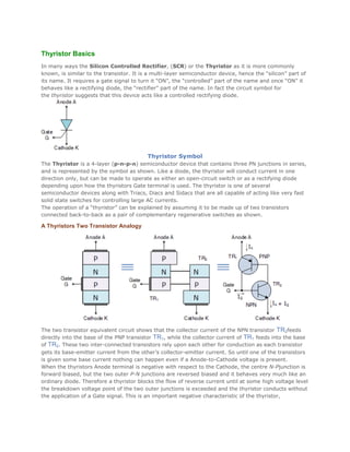
  • 1. Thyristor Basics In many ways the Silicon Controlled Rectifier, (SCR) or the Thyristor as it is more commonly known, is similar to the transistor. It is a multi-layer semiconductor device, hence the “silicon” part of its name. It requires a gate signal to turn it “ON”, the “controlled” part of the name and once “ON” it behaves like a rectifying diode, the “rectifier” part of the name. In fact the circuit symbol for the thyristor suggests that this device acts like a controlled rectifying diode. Thyristor Symbol The Thyristor is a 4-layer (p-n-p-n) semiconductor device that contains three PN junctions in series, and is represented by the symbol as shown. Like a diode, the thyristor will conduct current in one direction only, but can be made to operate as either an open-circuit switch or as a rectifying diode depending upon how the thyristors Gate terminal is used. The thyristor is one of several semiconductor devices along with Triacs, Diacs and Sidacs that are all capable of acting like very fast solid state switches for controlling large AC currents. The operation of a “thyristor” can be explained by assuming it to be made up of two transistors connected back-to-back as a pair of complementary regenerative switches as shown. A Thyristors Two Transistor Analogy The two transistor equivalent circuit shows that the collector current of the NPN transistor TR2feeds directly into the base of the PNP transistor TR1, while the collector current of TR1 feeds into the base of TR2. These two inter-connected transistors rely upon each other for conduction as each transistor gets its base-emitter current from the other’s collector-emitter current. So until one of the transistors is given some base current nothing can happen even if a Anode-to-Cathode voltage is present. When the thyristors Anode terminal is negative with respect to the Cathode, the centre N-Pjunction is forward biased, but the two outer P-N junctions are reversed biased and it behaves very much like an ordinary diode. Therefore a thyristor blocks the flow of reverse current until at some high voltage level the breakdown voltage point of the two outer junctions is exceeded and the thyristor conducts without the application of a Gate signal. This is an important negative characteristic of the thyristor,
  • 2. as Thyristors can be unintentionally triggered into conduction by an overvoltage as well as high temperature or a rapidly rising dv/dt voltage such as a spike. If the Anode terminal is positive with respect to the Cathode, the two outer P-N junctions are forward biased but the centre N-P junction is reverse biased. Therefore forward current is also blocked. If now a positive current is injected into the base of the NPN transistor TR2, the resulting collector current flows in the base of transistor TR1. This in turn causes a collector current to flow in the PNP transistor, TR1 which increases the base current of TR2 and so on. Typical Thyristor Very rapidly the two transistors force each other to conduct to saturation as they are connected in a regenerative feedback loop. Once triggered into conduction, the current flowing through the device between the Anode and the Cathode is limited only by the resistance of the external circuit. Then a thyristor can be turned “ON” and made to act like a normal rectifying diode by the application of a positive current to the base of transistor, TR2 which for a silicon controlled rectifier is called the “Gate” terminal. Once the thyristor has been turned “ON” and is conducting in the forward direction (anode positive), the gate signal looses control due to the regenerative latching action of the two internal transistors. Then applying a momentary Gate pulse to the device is enough to cause it to conduct and will remain permanently “ON” even if the gate signal is completely removed. Then the thyristor can also be thought of as a Bistable Switch having two states “ON” or “OFF”, as once it is triggered “ON” it cannot be turned “OFF” again by its Gate. So how do we turn “OFF” the thyristor?. Once the thyristor has self-latched into its “ON” state, it can only be turned “OFF” again by removing the supply voltage and therefore the Anode current completely or by reducing the Anode to Cathode current by external means to below a value commonly called the “minimum holding current”, (IH). The Anode current must therefore be reduced below this minimum holding level long enough for the thyristorsinternalP-N junctions to recover their blocking state before a forward voltage is again applied to the device without conduction. Since the thyristors turns “OFF” whenever the Anode current is reduced below this minimum value, it follows then that the device automatically turns “OFF” in AC circuits near to the crossing point at each half cycle and as we now know, remains “OFF” until the application of a Gate trigger pulse. Since an AC sinusoidal voltage continually reverses in polarity every half-cycle allowing the thyristor to turn “OFF”, this effect is known as “natural commutation” and is a very important characteristic of the silicon controlled rectifier. Thyristor Phase Control
  • 3. Thyristors used in circuits fed from DC supplies, this natural commutation condition cannot occur as the DC supply voltage is continuous so some other way to turn “OFF” the thyristor must be provided at the appropriate time. However in AC sinusoidal circuits natural commutation occurs every half cycle. Then during the positive half cycle of an AC sinusoidal waveform, the thyristor is forward biased (anode positive) and a can be triggered “ON” using a Gate signal or pulse. During the negative half cycle, the Anode becomes negative while the Cathode is positive. The thyristor is reverse biased by this voltage and cannot conduct even if a Gate signal is present. So by applying a Gate signal at the appropriate time during the positive half of an AC waveform, the thyristor can be triggered into conduction until the end of the half cycle. Thus phase control (as it is called) can be used to trigger the thyristor at any point along the positive half of the AC waveform and one of the many uses of a Silicon Controlled Rectifier is in the power control of AC systems. Thus far we have seen that a thyristor is essentially a half-wave device and conducts in only the positive half of the cycle when the Anode is positive and blocks current flow like a diode when the Anode is negative, irrespective of the Gate signal. But there are more semiconductor devices available which come under the banner of “Thyristor” that can conduct in both directions, full-wave devices, or can be turned “OFF” by the Gate signal. Such devices include “Gate Turn-OFFThyristors” (GTO), “Static Induction Thyristors” (SITH), “MOS Controlled Thyristors” (MCT), “Silicon Controlled Switch” (SCS), “Triode Thyristors” (TRIAC) and “Light Activated Thyristors” (LASCR) to name a few, with all these devices available in a variety of voltage and current ratings making them attractive for use in applications at very high power levels. Thyristor Summary Silicon Controlled Rectifiers known commonly as Thyristors are three-junction PNPN semiconductor devices which can be regarded as two inter-connected transistors that can be used in the switching of heavy electrical loads. They can be latched-”ON” by a single pulse of positive current applied to their Gate terminal and will remain “ON” indefinitely until the Anode to Cathode current falls below their minimum latching level. Static Characteristics of a Thyristor 1. 2. 3. 4. Conducts current only when forward biased and there is triggering current applied to the gate. The thyristor acts like a diode once it is “ON”. Blocks current flow when reverse biased, no matter if there is gate current applied. Once triggered “ON”, will be latched “ON” conducting even when the gate current is no longer applied. Thyristors are high speed switches that can be used to replace electromechanical relays in many circuits as they have no moving parts, no contact arcing or suffer from corrosion or dirt. But in addition to simply switching large currents “ON” and “OFF”, thyristors can be made to control the mean value of an AC load current without dissipating large amounts of power. A good example of thyristor power control is in the control of electric lighting, heaters and motor speed. In the next part of this tutorial we will look at some basic Thyristor circuits and applications using both AC and DC supplies.
  • 4. Thyristors: Principles of Operation A thyristor, also known as a SCR (silicon controlled rectifier), is a special type of diode that only allows current to flow when a control voltage is applied to it's gate terminal. Although this appears to be nothing more than a voltage controlled switch the following should be noted: In the presence of forward current (i.e. after the thyristor is turned on by a suitable gate voltage) it will not turn off even after the gate voltage has been removed. The thyristor will only turn off when the forward current drops to zero. In a DC (Direct current) circuit this makes the device almost useless except in certain particular safety (crowbar) protection applications. The most common use of thyristors is in AC (Alternating Current) circuits. In an AC circuit the forward current drops to zero during every cycle so there will always be a turn off function. This does , however, mean that the gate needs to be triggered every cycle just to turn it back on again. It is in the relative timing of these two functions that the thyristor has it's most important role, i.e. Power Control. Consider the waveform shown that corresponds to a typical AC voltage supply. If the thyristor is turned on near the beginning of the positive voltage excursion then the time it is forward conducting is maximised. This means maximum power delivered to the load. Correspondingly if it is turned on near the end of the positive excursion then minimum conduction time is achieved and minimum power delivered. By suitable timing control of the gate voltage a crude power controller can be designed to, for example, control the heating level of a simple resistive heater. As you can see from the diagram only half of the AC cycle is available for control since the entire negative half is in the wrong direction for the thyristor to conduct (diode action). This is rather wasteful and a much better option is to use two thyristors (back to back) to control the conduction in both directions. A device specifically designed to do this is called a TRIAC and is shown be