P4 Architecture by Jasper Moelker

This document provides a summary of a master's thesis project focused on redeveloping the center of the Teleport Area in Amsterdam to make it more efficient, continuous, and livable. The study examines the urban context through analysis of zoning, infrastructure, and adjacent areas. Design objectives are to re-connect, intensify use, and humanize the space. A conceptual masterplan proposes a mixed-use, multi-layered approach with housing, offices, shops, and other facilities organized around optimized infrastructure and public spaces. A cluster within the masterplan is then designed in more detail to demonstrate feasibility, focusing on light/visibility, flexibility of mixed programs. Finally, a sample building within the cluster is designed to balance connectivity with

Empfohlen
Empfohlen
Weitere ähnliche Inhalte
Ähnlich wie P4 Architecture by Jasper Moelker
Ähnlich wie P4 Architecture by Jasper Moelker (20)
Mehr von Jasper Moelker
Mehr von Jasper Moelker (20)
Kürzlich hochgeladen
Kürzlich hochgeladen (20)
P4 Architecture by Jasper Moelker
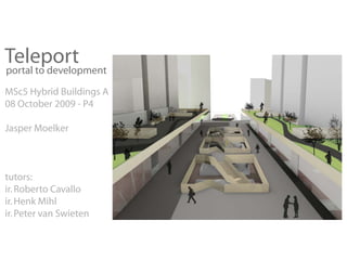
- 1. Teleport portal to development MSc5 Hybrid Buildings A 08 October 2009 - P4 Jasper Moelker tutors: ir. Roberto Cavallo ir. Henk Mihl ir. Peter van Swieten
- 2. Teleport portal to development Study question: ‘By what design intervention can the center of the Teleport Area be transformed into a more efficient, continuous and liveable environment?’
- 3. study question urban analysis objectives URBAN objectives concept urban concept building design BUILDING masterplan circulation building construction installation facade layout system system proof system light & visibility by case study mixed program objectives BLOCK flexibility concept appearance cluster design proof system by case study
- 4. study question urban analysis objectives URBAN objectives concept urban concept building design BUILDING masterplan circulation building construction installation facade layout system system proof system light & visibility by case study mixed program objectives BLOCK flexibility concept appearance cluster design proof system by case study
- 5. Urban design Location // Teleport Teleport
- 6. Urban design Analysis // zoning a o n s y l o n i
- 7. Urban design Analysis // infrastructure Higway A10 Cruise Terminal Train Metro
- 8. Urban design Analysis // adjacent areas ( Amsterdam center ) A10 highway office area office area metro Sloterdijk train station car, bus, tram
- 9. Urban design Objectives TELEPORT office area TELEPORT office area Sloterdijk station OBJECTIVES: > re-connect > intensify > humanize
- 10. Concept Urban design Concept // re-connect Teleport as transport hub the membrane a green “band aid”
- 11. Urban design Concept // intensify
- 12. Urban design Concept // humanize
- 13. Urban design ves Masterplan // approach --> housing mixed --> offices --> shops program --> catering industry --> other facilities --> highrise multiple layers --> facilities --> slow traffic } program > re-connect > intensify ify --> fast traffic } infrastructure > humanize n urban spacee --> extend train platforms optimized --> bus / tram terminal --> parking facilities infrastructure --> distribution routes --> separate slow traffic --> visibility & overview --> wide street profiles comfort --> light --> parks & terraces --> green & safety --> control people flow --> use of daylight --> closeable areas --> physiological aspects
- 14. Urban design Setting Masterplan // setting Highway A10 Highway A10 Sloterdijk Station Sloterdijk Station
- 15. Urban design Masterplan // infrastructure Cars Car route ar r ute (new) Tram + Bus ra us (new) Trains Tram Metro
- 16. Urban design Masterplan // park-over / network / building mass Highrise & Boulevards (highrise) (highrise) (highrise)
- 17. Urban design Masterplan // infrastructure infrastructure asis e ra ar e n r car r ute rain stati n entrances us ra istri uti n er inal r ute ra ar e ar par aarle er e
- 18. Urban design Masterplan // parking
- 19. Urban design Masterplan // parks / boulevards / facilities not full detailed not full detailed not full detailed
- 20. Urban design Masterplan // highrise
- 21. Urban design Masterplan // impression
- 22. Cluster study question urban analysis objectives URBAN objectives concept urban concept building design BUILDING masterplan circulation building construction installation facade layout system system proof system light & visibility by case study mixed program objectives BLOCK flexibility concept appearance cluster design proof system by case study
- 23. Cluster Objectives METHOD : STUDY CLUSTER TO PROOF THE USABILIT Y OF THE MASTERPLAN OBJECTIVES: > light & visibility > flexibility to accommodate mixed program > dwellings > offices > retail > catering industry > other facilities
- 24. Cluster Concept Light Highrise corridors on strip Strip with facilities Bus + Tram Train Car Park Terminal Platforms
- 25. Cluster Concept Highrise on strip level +01 : highrise (offices, hotels, dwellings) Strip with p Light g (and up) facilities l Courtyard atrium r m level +00 : facilities (fun shopping); entrances level -01 : facilities (run shopping) level -02 : construction, installations, distribution level -03 : infrastructure (fast traffic)
- 26. Cluster Platforms (-03) outline of towers above light corridor atrium
- 27. Cluster Parking (-02) outline of towers above light corridor atrium
- 28. Cluster Boulevard (-01) outline of towers above light corridor atrium
- 29. Cluster Ground floor (+00) light corridor atrium
- 32. Building study question urban analysis objectives URBAN objectives concept urban concept building design BUILDING masterplan circulation building construction installation facade layout system system proof system light & visibility by case study mixed program objectives BLOCK flexibility concept appearance cluster design proof system by case study
- 33. Building Objectives METHOD : CREATE BUILDING DESIGN TO PROOF THE USABILIT Y OF THE CLUSTER DESIGN OBJECTIVES: > light & visibility > mixed program > flexibility (change usage over time) > appearance CONTSTRAINTS: > building above train tracks and platforms
- 34. Building Concept // basis CONNECT & OPEN UP
- 35. Building Concept // sight CONNECT & OPEN UP
- 36. Building Concept // circulation CONNECT & OPEN UP
- 37. Building Concept // orientation CONNECT & OPEN UP
- 38. Building Concept // privacy CONNECT & OPEN UP
- 39. Building Concept // construction CONNECT & OPEN UP
- 40. Building Concept // installations CONNECT & OPEN UP
- 41. Building Concept // facade CONNECT & O CO C OPEN UP U
- 43. Building // circulation Clustering studies Solo towers w/ mono core Tower pair w/ dual core + ring Tower cluster w/ quad core + ring
- 44. Building // circulation Core studies Core embedded in void Core plugged into towers
- 46. Building // circulation Organization A B A (stairs) (elevators) (stairs)
- 48. Building // circulation Entrance Entrance residents Entrance visitors boulevard side on park level
- 53. Building // construction System Joints steel column tubular pro file 200 x 200 concrete core braces braces facade column - beam core column - beam hinge joint clamped joint Section AA1 steel facade column edge beam tubular profile 120 x 80 IPE 170 concrete core 5700 edge beam main beam steel column IPE 200 w/ one side IPE 200 w/ main beam tubular pro file 200 x 200 extended lower flange extended lower flange IPE 320 concrete core 1350 1350 braces 1350 5700 2700 2700 3600 3600 2700 2700 2000 2000 Plan upper floors Section BB1
- 54. Building // construction Flow of forces
- 55. Building // installations Concept > one core per tower > service zone in tower center (in suspended ceiling) > other services in floors > climate in combination w/ facade
- 56. Building // installations System mechanical ventilation pre cooled / heated > HEATING per dwelling / office > DRAINAGE suspended ceiling natural ventilation direct or indirect > ELECTRICITY vertical through facade panels > VENT SYS in PLAN distribution Section AA3 5700 services above suspended ceiling 1350 1350 stairs & lifts vertical distribution 1350 suspended ceiling low temerature surface heating in top of floor system or 5700 in additional dry floor system (adjustable to floor usage) 2700 2700 3600 3600 2700 2700 2000 2000 Plan upper floors Section BB1
- 57. Building // installations Heating and ventilation no indirect direct ventilation ventilation ventilation Natural ventilation Low surface heating > no ventilation (closed) > low surface heating in > indirect (pre heated) ventilation (4-10 deg) floor system (IDES) > direct ventilation ( > 10 deg) > if required placed in dry floor system on top (for extra insulation)
- 58. Building // installations Heating and ventilation - AIR IN + via bridge on HEAT REGULATION VaV VaV courtyard side pre cool / heat using min / max water system (running + - depends on + - through vertical shaft) function via bridge on boulevard side HEAT EXCHANGE FANS AIR OUT in suspended ceiling DWELLING OFFICE in core area VaV Mechanical ventilation > in addition to natural ventilation > air in/out via bridge > heat regulation using water system (distribution via shafts in core) > variable air volume (VaV) system depends on function (dwellings / offices / ... )
- 59. Building // facade Concept > contact vs privacy > day light vs sun shading > expression (of activity)
- 60. Building // facade Pattern & lighting
- 61. Building // facade System 900 x 900 x 4mm PC OUT IN min cover 20% max cover 95% black -> silver Polycarbonate (PC) OUT highly transparant lightweight (1200kg/m3) 30 - 30 - 30 - 30mm (not to scale) temperature resistance impact resistance thermoplastic (recyclable) IN
- 62. Building // facade Detail // vertical
- 63. Building // facade Detail // horizontal
- 64. Building // facade Simulation Prototype Rendering
- 67. Building // facade Impression lighting
- 68. Building // layout Concept > accommodate different programs > changeable over time > orient towards park or boulevard > more private activities towards center
- 69. Building // layout Dwellings (+05) DWELLING A+ DWELLING A DWELLING B DWELLING C DWELLING A+ DWELLING A DWELLING B
- 70. Building // layout Dwellings (+06) DWELLING A+ DWELLING D DWELLING C DWELLING A+ DWELLING D
- 71. Building // layout Dwelling example
- 72. Building // layout Offices (+10) OFFICE UNITS OFFICE DESKSCAPE