Mpls layer 3 vp ns
•Als DOCX, PDF herunterladen•
1 gefällt mir•451 views

Mpls layer 3 vp ns. More...

Empfohlen
Weitere ähnliche Inhalte
Was ist angesagt?
Was ist angesagt? (20)
Andere mochten auch
Andere mochten auch (6)
Ähnlich wie Mpls layer 3 vp ns
Ähnlich wie Mpls layer 3 vp ns (20)
Mehr von IT Tech
Mehr von IT Tech (20)
Kürzlich hochgeladen
Kürzlich hochgeladen (20)
Mpls layer 3 vp ns
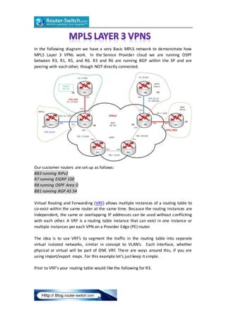
- 1. In the following diagram we have a very Basic MPLS network to demonstrate how MPLS Layer 3 VPNs work. In the Service Provider cloud we are running OSPF between R3, R1, R5, and R6. R3 and R6 are running BGP within the SP and are peering with each other, though NOT directly connected. Our customer routers are set up as follows: BB3 running RIPv2 R7 running EIGRP 100 R8 running OSPF Area 0 BB1 running BGP AS 54 Virtual Routing and Forwarding (VRF) allows multiple instances of a routing table to co-exist within the same router at the same time. Because the routing instances are independent, the same or overlapping IP addresses can be used without conflicting with each other. A VRF is a routing table instance that can exist in one instance or multiple instances per each VPN on a Provider Edge (PE) router. The idea is to use VRF’s to segment the traffic in the routing table into seperate virtual isolated networks, similar in concept to VLAN’s. Each interface, whether physical or virtual will be part of ONE VRF. There are ways around this, if you are using import/export maps. For this example let’s just keep it simple. Prior to VRF’s your routing table would like the following for R3.
- 2. So, to get started, we are going to create 2 different VRF’s: R7 and BB1 will be in VRF_RED BB3 and R8 will be in VRF_BLUE First, let’s set up MPLS across the Core of the SP network (R3, R1, R5, and R6). These interface configs will only be on the inward-facing interfaces. No need to add anything (YET) to the customer facing interfaces. See below: Next, let’s create VRF_RED and VRF_BLUE on R3 to segment the customer’s traffic:
- 3. The Route Distingisher (RD) can be in the format [ASN:nn|IP-address:nn]. This is what makes the prefix globally unique if you happen to have 2 customers with the same IP addressing scheme. The route-target(RT) is an extended BGP community that indicates which routes should be imported/exported from MP-BGP into the VRF. So, all we’re saying here is that VPN_RED is going to import and export 100:1 ID’d traffic and VPN_BLUE is going to import export 100:2 ID’d traffic. Next, we will add interface f0/0 and f0/1 to their corresponding VRF on R3: **Note** As soon as you add the ‘ip vrf’ statement, you get the following message: % Interface FastEthernet0/0 IP address 10.1.37.3 removed due to enabling VRF VPN_RED The reason behind this is that you are segmenting the interface and creating a new routing table, so you can’t have the same IP address on f0/0 and on “f0/0
- 4. VPN_RED”. So be sure to go back and add your IP address to the interface. Now, look at how your routing table has changed. The show ip route command only shows the routes internal to the Service Provider. The show ip route vrf VPN_RED only shows the connected route to R7. The show ip route vrf VPN_BLUE only shows the connected route to BB3 Also, note the change in syntax while issuing the ping command: At this point our VRF’s are up and functional, but we still need to have end to end connectivity from R7 to BB1, and from BB3 to R8. On R3 and R6 your IGP routing processes are not doing anything now because they were not specifically configured for the VRF’s. A separate “address-family” will need to be configured under the corresponding IGP process before routing information can be passed. Once you are under the “address-family” the config parser is pretty much the same.
- 5. And now your routing table shows all of your local VRF learned routes. But still we do not have end to end connectivity. Don’t forget to redistribute the IGP routes back into BGP under the “address-family ipv4 VRF” sub-process. Also note the addition of the “address-family vpnv4″ sub process. This is where your RD/RT community is sent between iBGP peers (mentioned previously).
- 6. Similar configs are needed for R6 BGP address family. Next, test connectivity. Troubleshooting: Traceroute from R7 to 112.0.0.1 (loopback 112 on BB1) to see the labels at each hop. You can see that at R3 Label 18 is added and pushed to R1. Then, on R1, label 18 is swapped for label 16 and sent to R5. R5 pops the label and sends the packet to R6, which has a route to 112.0.0.1. Packets with Label 18 are sent out s0/0 towards the VPNv4 tunnel dest of 150.1.6.6.(Lo0 R6)
- 7. R1 receives Label 18, swaps it for Label 16 and sends packet to R5. R5 recieves Label 16, Pops the tag off and send packet to R6 (150.1.6.6). R6 receives packet destined for 112.0.0.1 and sends untagged out S0/0.1. As you can see, both VRF’s have full connectivity (within their own VRF), and we are able to verify the push/swap/pop process along the path. All of this is done without R1 and R5 having any knowledge whatsoever of BGP or the global routing table. This is what prevents SP’s from needing full-mesh BGP topologies holding the entire internet routing table. MPLS VPN’s using VRF’s segment the customer traffic (essentially like GRE) so that they have no knowledge of each other. More Related Networking Topics:
- 8. WAYS to Help You Set Up Your Small, Medium and Large Networks Cisco ASA Failover, Failover Modes & ASA Failover Configuration Check Cisco Routers and Switches Using the IOS Environment Command Cisco Unified Access Review