Generative Artificial Intelligence: How generative AI works.pdf
Configuring cisco asa and pix firewalls part2
1. How to Create a Cisco ASA or PIX Firewall-Part2
To create a firewall object to represent your Cisco ASA device, click on the “Create
new firewall” icon in the main window of Firewall Builder, or right-click on the
Firewalls system folder in the object tree and select "New Firewall". Either of these
methods will launch a wizard that walks you through creating your firewall object.
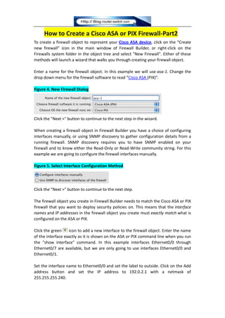
Enter a name for the firewall object. In this example we will use asa-1. Change the
drop down menu for the firewall software to read “Cisco ASA (PIX)”.
Figure 4. New Firewall Dialog
Click the "Next >" button to continue to the next step in the wizard.
When creating a firewall object in Firewall Builder you have a choice of configuring
interfaces manually, or using SNMP discovery to gather configuration details from a
running firewall. SNMP discovery requires you to have SNMP enabled on your
firewall and to know either the Read-Only or Read-Write community string. For this
example we are going to configure the firewall interfaces manually.
Figure 5. Select Interface Configuration Method
Click the "Next >" button to continue to the next step.
The firewall object you create in Firewall Builder needs to match the Cisco ASA or PIX
firewall that you want to deploy security policies on. This means that the interface
names and IP addresses in the firewall object you create must exactly match what is
configured on the ASA or PIX.
Click the green icon to add a new interface to the firewall object. Enter the name
of the interface exactly as it is shown on the ASA or PIX command line when you run
the "show interface" command. In this example interfaces Ethernet0/0 through
Ethernet0/7 are available, but we are only going to use interfaces Ethernet0/0 and
Ethernet0/1.
Set the interface name to Ethernet0/0 and set the label to outside. Click on the Add
address button and set the IP address to 192.0.2.1 with a netmask of
255.255.255.240.
2. Figure 6. Set Interface IP Address
Click the green icon to add another interface to the firewall object. Enter the
information in to the wizard to match the second interface as follows:
Figure 7. Interface Tabs
Click the "Next >" button.
Firewall Builder will automatically set the security level of the interface based on the
interface label and IP address. The outside interface is set to security level 0 and the
inside interface is set to security level 100.
Figure 8. Interface Security Levels
Click the "Finish" button to create the firewall object.
After you create the firewall object representing the ASA or PIX, it is displayed in the
object panel on the left side. The Policy object, where the access list rules are
configured, is automatically opened in the main window.
Figure 9. Firewall Displayed in Object Tree
3. 4.1. Network Zones
Firewall Builder uses a Network Zone concept to determine network topology and
correctly create rules. Each firewall object interface has a corresponding Network
Zone that must be set. The Network Zone represents the set of source IP networks
sending traffic inbound to an interface.
Figure 10. Network Zones Define Topology
Note
Warning! If you do not set the Network Zone, Firewall Builder will generate an
error when you try to compile the firewall object to generate the configuration file.
Outside Interface
For the "outside" interface, Ethernet0/0 in this example, you will typically set the
Network Zone to "Any". "Any" is defined to be all IP networks that aren't associated
with any other interfaces. To set the Network Zone double-click the Ethernet0/0
interface object of the firewall object and select the Network Zone "Any" from the
dropdown list.
Figure 11. Setting Network Zone For The "outside" Interface
4. Inside Interface
For the "inside" interface, and all other interfaces on the firewall object, you need to
select a Network Zone based on the your network topology. In our firewall example
object the "inside" interface is attached to the 10.10.10.0/24 network. Firewall
Builder comes with a predefined object called net-10.0.0.0 which represents the
10.0.0.0 network. We will use this network for the "inside" interface Network Zone.
Figure 12. Setting Network Zone For The "inside" Interface
Note
A Network Zone can be an individual Network object or a Group object that includes
5. multiple Network objects. For example, you must set the Network Zone to a Group
object if your internal network uses the 10.0.0.0/8 and 172.16.0.0/16 networks. In
this case you create a Group object, include network objects for both of these IP
networks, and use this Group object as your "inside" interface's Network Zone.
Before moving on you should save the data file containing the new firewall object
just created. Do this by going to the "File -> Save As" menu item. Choose a name and
location to save the file.
More Related Cisco Firewall Tips:
Cisco Guide: Migration of Cisco PIX 500 Series to Cisco ASA 5500 Series
Cisco PIX Firewall Basics