Flyport openPicus datasheet
•
0 gefällt mir•776 views

Flyport Wi-Fi is a miniature web server module featuring a fully integrated 802.11 b/g/n Wi-Fi interface and several interfaces for the ‘real world’.

Empfohlen
Empfohlen
Weitere ähnliche Inhalte
Was ist angesagt?
Was ist angesagt? (20)
Andere mochten auch
Andere mochten auch (8)
Ähnlich wie Flyport openPicus datasheet
Ähnlich wie Flyport openPicus datasheet (20)
Mehr von Ionela
Mehr von Ionela (20)
Kürzlich hochgeladen
Kürzlich hochgeladen (20)
Flyport openPicus datasheet
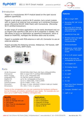
- 1. 802.11 Wi-Fi Smart module powered by openPICUS Introduction Features Flyport is a revolutionary Wi-Fi module based on the open source platform openPICUS. • 802.11 b/g/n WIFI Flyport is not simply a serial to Wi-Fi solution, but a smart module with no need of an external host processor as it combines Processor • Microchip PIC 24F 16 bit power (Microchip PIC24F 256K Flash) with Connectivity (Microchip processor Wi-Fi certified transceiver). • Microchip Wi-Fi Module A wide range of wireless applications can be easily developed and run MRF24WB0MA/RM (PCB antenna or uFL) on Flyport with openPicus IDE and no Wi-Fi expertise is needed. The IDE allows to focus on application as openPicus framework, which is • openPICUS Free IDE based on freeRTOS, manages the Wireless stack and its events. • Wireless stack and appli- Flyport is available with PCB antenna or with uFL Connector to use an cation run on the external antenna. microcontroller Flyport provides the following services: Webserver, TCP Socket, UDP • Serial bootloader Socket, SMTP Client, SNTP Client. • Webserver, email client, SNTP, SMTP, TPC/UDP socket • 5V or 3,3V power supply • Most of the pins are remappable at Runtime • #10 Digital I/O • #4 Analog Inputs Facts • #9 PWM 16 Bit Processor PIC24FJ256,256K Flash,16K Ram,16Mips@32Mhz Transceiver 802.11 b/g/n Wi-Fi certified MRF24WB0MB • #1 UART Power Supply 5V or 3,3V, integrated LDO Integrated RTC 32,768 Khz quartz onboard • #1 SPI Digital I/O up to 18, remappable at Runtime Analog In up to 4, 10bits ADC, Vref=2,048V • #1 I2C Communication up to 4 UART, 2 SPI, 1 I2C Connector 26 ways, 2 rows, standard 2.54mm male pin header • Real Time Clock Onboard Dimensions 35 x 48 x 7 mm, 11 grams (not battery) Thanks to the remappable pins you can customize the hardware configura- • Compact 35X48X7 mm tion by firmware, at runtime, according to your needs. For example you can have up to 4 UART Ports, 9 PWM or 18 Digital I/Os. • Light 11 gr Benefits Applications • Easy to setup • Wi-Fi sensors • Easy to manage and use • Wi-Fi automation • Low power • Internet of things • Zero Time for development • Wi-Fi enterteinment • Open source • Serial to Wi-Fi eikon srl Via G.Peroni 442 Rome (Italy) info@eikonsite.it www.eikonsite.it tel +39 06 92916378 Rev.4 08 Jun 2011 P1
- 2. 802.11 Wi-Fi Smart module powered by openPICUS Block diagram A N WIFI MODULE T E Microchip MRF24WB0MA N N A UART SPI I2C Microprocessor RTC Quartz 32.768 Khz Microchip PIC 24FJ256GA106 DIGITAL INPUTS 256k FLASH MEMORY Wireless Stack+ Application CPU Quartz ANALOG INPUTS 32Mhz DIGITAL OUTPUTS / PWM RESET Voltage reference IC LDO regulator Vref=2,048V 5V -> 3,3V +5V or +3,3V GND eikon srl Via G.Peroni 442 Rome (Italy) info@eikonsite.it www.eikonsite.it tel +39 06 92916378 Rev.4 08 Jun 2011 P2
- 3. 802.11 Wi-Fi Smart module powered by openPICUS Pin Description 5V Pin Default name Default Function Remappable Pin Tolerant 1 I2C_clk I2C bus Clock signal Yes No 2 D5_in Digital input #5 Yes Yes 3 I2C_data I2C bus Data signal Yes No 4 D1_out Digital output #1 Yes Yes 5 D1_in Digital input #1 Yes Yes 6 D2_out Digital output #2 Yes Yes 7 D2_in Digital input #2 Yes No 8 SPI_clk SPI bus clock (SCLK) Yes Yes 9 D3_in Digital input #3 Yes Yes 10 SPI_out SPI bus Output (SDO) Yes Yes 11 D4_in Digital input #4 Yes Yes 12 SPI_in SPI bus Input (SDI) Yes Yes 13 uRX_in UART RX input Yes Yes 14 SPI_cs SPI bus chip select (CS) Yes Yes 15 uTX_out UART TX output Yes Yes 16 +5V Power input. See note 1. - - 17 D3_out Digital output #3 No Yes 18 PGC/A4_in Analog input #4 (note 2) No Yes 19 D4_out Digital output #4 (connected on red Led OUT4) No Yes 20 PGD/A3_in Analog input #3 (note 2) No Yes 21 D5_out Digital output #5 (connected on red Led OUT5) No No 22 GND Ground - - 23 A1_in Analog input #1 No Yes 24 +3,3V Power input/output (note 1) - - 25 A2_in Analog input #2 No Yes 26 Reset Reset (Active Low) No - Remappable pins is a useful feature of Microchip PIC processors that let the user can customize the hardware configuration at runtime. It means that you can have up to 4 UARTs or up to 18 Digital I/Os. It’s possible to have up to 9 independent PWMs. Note 1. Flyport can be powered at 3.3V OR at 5V. If the module is powered by 5V on pin 16, pin 24 is the output of integrated LDO (max output current available:100mA). If Flyport is powered using single 3,3V on pin 24 leave pin 16 unconnected! Note 2. Pins 16-18-20-22-24-26 are pin to pin compatible with the Microchip PicKit programmer connector. Note on PROGRAMMING: to make code easier D5_out becomes d5out on code, don’t use the underscore symbol. eikon srl Via G.Peroni 442 Rome (Italy) info@eikonsite.it www.eikonsite.it tel +39 06 92916378 Rev.4 08 Jun 2011 P3
- 4. 802.11 Wi-Fi Smart module powered by openPICUS Technical Informations Electrical 802.11 WIFI Power supply 5V or 3,3V Compatibility b/g/n networks Current consumption TX 154mA RX 85mA Output power 10dBm SLEEP 250µA IDLE 0.1µA Sensitivity -91dBm Max Data Rate 2 Mbit Mechanical Certifications Operating Temperature -40..+85°C Radio regulation certification for United States (FCC), Canada (IC), Europe (ETSI) and Japan (ARIB) Dimensions 35*48*7mm Wi-Fi® certified (WFA ID: WFA7150) Weight 11 gr eikon srl Via G.Peroni 442 Rome (Italy) info@eikonsite.it www.eikonsite.it tel +39 06 92916378 Rev.4 08 Jun 2011 P4
- 5. 802.11 Wi-Fi Smart module powered by openPICUS Mechanical info flyPORT has a 2.5mm hole to fix the module against vibrations. flyPORT is provided with a standard con- nector: 2*13 ways (0.1”) 2,54mm Male Pin header connector. The connector fits standard 2*13 Fe- male pin header or with a Flat cable IDC connector. Note for PCB development: 1. Flyport integrated PCB antenna version: please don’t put any com- ponent, tracks or ground planes un- der the antenna. 2. Flyport uFL connector: use a 50ohm coaxial cable to connect the external 2.4Ghz antenna I eikon srl Via G.Peroni 442 Rome (Italy) info@eikonsite.it www.eikonsite.it tel +39 06 92916378 Rev.4 08 Jun 2011 P5
- 6. 802.11 Wi-Fi Smart module powered by openPICUS Applications development Please visit openPICUS project website www.openpicus.com to download the IDE, agetting started guide and some apps examples and libraries. USB Nest board is suggested in order to download firmware using the USB port of your PC. You don’t need any expansive programming tool: on flyPORT is present a Serial bootloader. ORDERING INFORMATION flyPORT openPICUS WI-FI MODULE (PCB ANTENNA) Product Code 015350 EAN 8055112971100 flyPORT openPICUS WI-FI MODULE (uFL ext.ANTENNA) Product Code 015353 EAN 8055112971110 Buy online on our website www.eikonsite.it or contact your local reseller. Eikon srl Local reseller Via Borgognina 5 61030 Lucrezia di Cartoceto (PU) Italy Vat IT02036680417 Tel +39 0721 877365 Fax +39 0721 897679 Web www.eikonsite.it Email info@eikonsite.it eikon srl Via G.Peroni 442 Rome (Italy) info@eikonsite.it www.eikonsite.it tel +39 06 92916378 Rev.4 08 Jun 2011 P6