
Empfohlen
Weitere ähnliche Inhalte
Was ist angesagt?
Was ist angesagt? (20)
Ähnlich wie GEOMETRIC OPTIMIZATION OF CNC VERTICAL MILLING MACHINE BED
Ähnlich wie GEOMETRIC OPTIMIZATION OF CNC VERTICAL MILLING MACHINE BED (20)
Mehr von Ijripublishers Ijri
Mehr von Ijripublishers Ijri (20)
Kürzlich hochgeladen
Kürzlich hochgeladen (20)
GEOMETRIC OPTIMIZATION OF CNC VERTICAL MILLING MACHINE BED
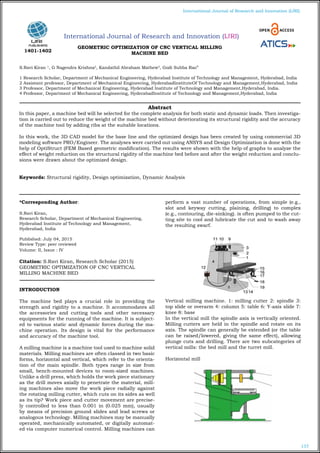
- 1. 157 International Journal of Research and Innovation (IJRI) International Journal of Research and Innovation (IJRI) GEOMETRIC OPTIMIZATION OF CNC VERTICAL MILLING MACHINE BED S.Ravi Kiran 1 , G Nagendra Krishna2 , Kandathil Abraham Mathew3 , Godi Subba Rao4 1 Research Scholar, Department of Mechanical Engineering, Hyderabad Institute of Technology and Management, Hyderabad, India 2 Assistant professor, Department of Mechanical Engineering, HyderabadInstituteOf Technology and Management,Hyderabad, India 3 Professor, Department of Mechanical Engineering, Hyderabad Institute of Technology and Management,Hyderabad, India. 4 Professor, Department of Mechanical Engineering, HyderabadInstitute of Technology and Management,Hyderabad, India *Corresponding Author: S.Ravi Kiran, Research Scholar, Department of Mechanical Engineering, Hyderabad Institute af Technology and Management, Hyderabad, India Published: July 04, 2015 Review Type: peer reviewed Volume: II, Issue : IV Citation: S.Ravi Kiran, Research Scholar (2015) GEOMETRIC OPTIMIZATION OF CNC VERTICAL MILLING MACHINE BED INTRODUCTION The machine bed plays a crucial role in providing the strength and rigidity to a machine. It accommodates all the accessories and cutting tools and other necessary equipments for the running of the machine. It is subject- ed to various static and dynamic forces during the ma- chine operation. Its design is vital for the performance and accuracy of the machine tool. A milling machine is a machine tool used to machine solid materials. Milling machines are often classed in two basic forms, horizontal and vertical, which refer to the orienta- tion of the main spindle. Both types range in size from small, bench-mounted devices to room-sized machines. Unlike a drill press, which holds the work piece stationary as the drill moves axially to penetrate the material, mill- ing machines also move the work piece radially against the rotating milling cutter, which cuts on its sides as well as its tip? Work piece and cutter movement are precise- ly controlled to less than 0.001 in (0.025 mm), usually by means of precision ground slides and lead screws or analogous technology. Milling machines may be manually operated, mechanically automated, or digitally automat- ed via computer numerical control. Milling machines can perform a vast number of operations, from simple (e.g., slot and keyway cutting, plaining, drilling) to complex (e.g., contouring, die-sinking). is often pumped to the cut- ting site to cool and lubricate the cut and to wash away the resulting swarf. Vertical milling machine. 1: milling cutter 2: spindle 3: top slide or overarm 4: column 5: table 6: Y-axis slide 7: knee 8: base In the vertical mill the spindle axis is vertically oriented. Milling cutters are held in the spindle and rotate on its axis. The spindle can generally be extended (or the table can be raised/lowered, giving the same effect), allowing plunge cuts and drilling. There are two subcategories of vertical mills: the bed mill and the turret mill. Horizontal mill Abstract In this paper, a machine bed will be selected for the complete analysis for both static and dynamic loads. Then investiga- tion is carried out to reduce the weight of the machine bed without deteriorating its structural rigidity and the accuracy of the machine tool by adding ribs at the suitable locations. In this work, the 3D CAD model for the base line and the optimized design has been created by using commercial 3D modeling software PRO/Engineer. The analyses were carried out using ANSYS and Design Optimization is done with the help of OptiStruct (FEM Based geometric modification). The results were shown with the help of graphs to analyze the effect of weight reduction on the structural rigidity of the machine bed before and after the weight reduction and conclu- sions were drawn about the optimized design. Keywords: Structural rigidity, Design optimization, Dynamic Analysis 1401-1402
- 2. 158 International Journal of Research and Innovation (IJRI) Horizontal milling machine. 1: base 2: column 3: knee 4 & 5: table (x-axis slide is integral) 6: overarm 7: arbor (at- tached to spindle) A horizontal mill has the same sort of x–y table, but the cutters are mounted on a horizontal arbor (see Arbor mill- ing) across the table. Many horizontal mills also feature a built-in rotary table that allows milling at various angles; this feature is called a universal table. While endmills and the other types of tools available to a vertical mill may be used in a horizontal mill, their real advantage lies in arbor-mounted cutters, called side and face mills, which have a cross section rather like a circular saw, but are generally wider and smaller in diameter. Because the cut- ters have good support from the arbor and have a larger cross-sectional area than an end mill, quite heavy cuts can be taken enabling rapid material removal rates. These are used to mill grooves and slots. Plain mills are used to shape flat surfaces. Several cutters may be ganged to- gether on the arbor to mill a complex shape of slots and planes. Special cutters can also cut grooves, bevels, ra- dii, or indeed any section desired. These specialty cut- ters tend to be expensive. Simplex mills have one spindle, and duplex mills have two. It is also easier to cut gears on a horizontal mill. Some horizontal milling machines are equipped with a power-take-off provision on the table. This allows the table feed to be synchronized to a rotary fixture, enabling the milling of spiral features such as hy- poid gears. Variants A miniature hobbyist mill plainly showing the basic parts of a mill. • Bed mill: • Box mill or column mill: • C-Frame mill: • Floor mill: • Gantry mill: • Horizontal boring mill: • Jig borer: • Knee mill or knee-and-column mill • Planer-style mill: • Ram-type mill: • Turret mill: Computer numerical control Thin wall milling of aluminum using a water based cut- ting fluid on the milling cutter Most CNC milling machines (also called machining cent- ers) are computer controlled vertical mills with the ability to move the spindle vertically along the Z-axis. This extra degree of freedom permits their use in diesinking, engrav- ing applications, and 2.5D surfaces such as relief sculp- tures. When combined with the use of conical tools or a ball nose cutter, it also significantly improves milling pre- cision without impacting speed, providing a cost-efficient alternative to most flat-surface hand-engraving work. Five-axis machining center with rotating table and computer in- terface MODELING OF MACHINE BED The above image shows milling machine base frame The above image shows milling machine bed supports The above image shows milling machine
- 3. 159 International Journal of Research and Innovation (IJRI) The above image shows milling machine bed base view The above image shows milling machine bed T slut cuts The above image shows milling machine with bed assembly view INTRODUCTION TO FEA Finite Element Analysis (FEA) was first developed in 1943 by R. Courant, who utilized the Ritz method of numerical analysis and minimization of variational calculus to ob- tain approximate solutions to vibration systems. Shortly thereafter, a paper published in 1956 by M. J. Turner, R. W. Clough, H. C. Martin, and L. J. Topp established a broader definition of numerical analysis. The paper cen- tered on the "stiffness and deflection of complex struc- tures". FEA consists of a computer model of a material or de- sign that is stressed and analyzed for specific results. It is used in new product design, and existing product re- finement. A company is able to verify a proposed design will be able to perform to the client's specifications prior to manufacturing or construction. Modifying an existing product or structure is utilized to qualify the product or structure for a new service condition. In case of structural failure, FEA may be used to help determine the design modifications to meet the new condition. There are generally two types of analysis that are used in industry: 2-D modeling, and 3-D modeling. While 2-D modeling conserves simplicity and allows the analysis to be run on a relatively normal computer, it tends to yield less accurate results. 3-D modeling, however, produces more accurate results while sacrificing the ability to run on all but the fastest computers effectively. Within each of these modeling schemes, the programmer can insert nu- merous algorithms (functions) which may make the sys- tem behave linearly or non-linearly. Linear systems are far less complex and generally do not take into account plastic deformation. Non-linear systems do account for plastic deformation, and many also are capable of testing a material all the way to fracture. FEA uses a complex system of points called nodes which make a grid called a mesh. This mesh is programmed to contain the material and structural properties which de- fine how the structure will react to certain loading condi- tions. Nodes are assigned at a certain density throughout the material depending on the anticipated stress levels of a particular area. Regions which will receive large amounts of stress usually have a higher node density than those which experience little or no stress. Points of interest may consist of: fracture point of previously tested material, fil- lets, corners, complex detail, and high stress areas. The mesh acts like a spider web in that from each node, there extends a mesh element to each of the adjacent nodes. This web of vectors is what carries the material properties to the object, creating many elements. STRUCTURAL ANALYSIS OF CNC VERTICAL MILLING MACHINE BED WITH “T” SLOT The above image shows imported model The above image shows meshed model
- 4. 160 International Journal of Research and Innovation (IJRI) BED MATERIAL: CAST-IRON The above image shows total deformation The above image shows stress MODEL ANALYSIS OF CNC VERTICAL MILLING MA- CHINE BED WITH “T” SLOT The above image shows total deformation mode 1 The above image shows total deformation mode 2 FATIGUE ANALYSIS OF CNC VERTICAL MILLING MA- CHINE BED WITH “T” SLOT The above image shows life STRUCTURAL ANALYSIS OF CNC VERTICAL MILLING MACHINE BED WITH “T” SLOT BED MATERIAL: S2-GLASS EPOXY The above image shows total deformation
- 5. 161 International Journal of Research and Innovation (IJRI) The above image shows stress STRUCTURAL ANALYSIS OF CNC VERTICAL MILLING MACHINE BED WITH “T” SLOT BED MATERIAL: ZAMAK The above image shows total deformation The above image shows stress STRUCTURAL ANALYSIS OF CNC VERTICAL MILLING MACHINE WITH “DOVETAIL” SLOT The above image shows “DOVETAIL” SLOT BED MATERIAL: CAST IRON The above image shows total deformation The above image shows stress
- 6. 162 International Journal of Research and Innovation (IJRI) STRUCTURAL ANALYSIS GRAPHS The above image shows displacement graph The above image shows stress graph The above image shows strain graph DYNAMIC ANALYSIS T- SLOT FOR S2 GLASS EPOXY The above image shows T- slot Total deformation The above image shows T- slot Stress The above image shows T- slot Strain DYNAMIC ANALYSIS “DOVETAIL” - SLOT FOR S2 GLASS EPOXY The above image shows “DOVETAIL” - slot Total deformation The above image shows “DOVETAIL” – slot Stress
- 7. 163 International Journal of Research and Innovation (IJRI) Results table STRUCTURAL ANALYSIS “T” SLOT “DOVETAIL” SLOT Total defor- mation 0.066494 0.02077 0.073073 0.065038 0.0207 0.071426 Stress 3.4113 4.0632 3.343 3.6862 4.3676 3.6138 Strain 4.382e-2 1.7647e- 5 4.9107e- 5 4.6479e-5 1.7646e- 5 5.2101 e-5 MODEL ANALYSIS Total defor- mation HZ 144.94 144.94 144.94 144.94 144.94 144.94 Total defor- mation HZ 168.77 274.92 167.42 170.29 274.92 168.98 Total defor- mation HZ 258.71 287.58 257.81 260.14 287.6 259.23 Total defor- mation HZ 262.89 322.2 260.44 264.33 322.22 262.08 Total defor- mation HZ 274.85 336.63 274.73 274.87 336.63 274.84 DYNAMIC ANALYSIS -“T” SLOT -- BED MATERIAL: S2-GLASS EPOXY 250HZ 500HZ 750HZ 1000HZ Total defor- mation 0.023288 0.068505 0.054208 0.021232 Stress 2.3258 17.613 28.121 10.472 Strain 2.5396e-5 9.0944e-5 7.938e-5 2.6878e-5 DYNAMIC ANALYSIS -“ DOVETAIL” SLOT -- BED MATERIAL: S2-GLASS EPOXY 250HZ 500HZ 750HZ 1000HZ Total defor- mation 0.023253 0.06915 0.058086 0.023151 Stress 2.3224 18.61 29.984 12.307 Strain 2.5344e-5 9.0381e-5 8.5479e-5 3.1111e-5 CONCLUSION This project work deals with “GEOMETRIC OPTIMIZA- TION OF VERTICAL CNC MACHINE BED USING FEM” to reduce cost and weight Bed is the main part in CNC machine which holds the entire work piece weight in moving condition. Machine is consuming more power to move bed along with parts, so this is an attempt to reduce the bed weight without reduc- ing its strength and capacity. Initially literature survey and data collection was done to understand methodology. Parametric models of CNC machine parts are prepared and assembly is made using prepared parts and convert- ed into IGES file to transfer into Ansys. Structural and model analysis is conducted to find stress concentration locations, structural behavior according to the material & natural frequency values. Dynamic analysis is conducted to evaluate results in load and vibration conditions. As per the analysis results S-2 glass bed with T-slots is showing good strength than previous models also by us- ing S-2 glass weight of the bed can be reduced up to 65% so better to use bed with T-slot with S-2 glass material. References 1.Performance Analysis of Vertical Machining Center through Process Capability 2.A Study on Design and Manufacturing for the Side Wall of Large CNC Portal Milling Machine 3.Structural Redesigning Of A Cnc Lathe Bedimprove Its Static And Dynamic Characteristics 4.Design And Structural Analysis Of Cnc Vertical Milling Ma- chine Bed 5.Implementation of neural network for monitoring and predic- tion of surface roughness in a virtual end milling process of a CNC vertical milling machine 6.Optimization of Input Process Parameters in CNC Milling Ma- chine of EN24 Steel 7.Design Optimization of Machining Fixture for the Slant Bed CNC Lathe author S.Ravi Kiran Research Scholar, Department Of Mechanical Engineering, HyderabadInstituteOf Technology And Management, Hyderabad,India G Nagendra Krishna Assistant professor Department of Mechanical Engineering, HyderabadInstitute of Technology and Management, Hyderabad,India Kandathil Abraham Mathew, Professor, Department of Mechanical Engineering, Hyderabad Institute of Technology and Management, Hyderabad,India Godi Subba Rao, (HOD) Professor,Department of Mechanical Engineering, Hyderabad Institute of Technology and Management, Hyderabad, India