SlideShare ist ein Scribd-Unternehmen logo
1 von 6
Downloaden Sie, um offline zu lesen
International Journal of Engineering Research and Development
e-ISSN: 2278-067X, p-ISSN: 2278-800X, www.ijerd.com
Volume 5, Issue 12 (February 2013), PP. 42-47

   Design, Modeling and Optimization of Spur Gear Using
                  Finite Element Analysis
                      K.N.D.Malleswara Rao1, Tippa Bhimasankar Rao2
         1
        PG Student, Department of Mechanical Engineering, Nimra Institute of Science and Technology
  2
   Hod, Department of Mechanical Engineering, Nimra Institute of Science and Technology, Vijayawada, AP,
                                                 India

      Abstract:-Gears are mainly used in the power or torque transmitting places. Other devices also there
      for transmitting the torque such as belt drive, chains drives because those have more disadvantages like
      slip. Gears are mainly used in lathes machines, automobiles and all torque transmitting units. Our
      project mainly deals with design, modeling and analysis of spur gear and Optimization of spur gear.
      For that we had considered a design problem and solved the problem with two different materials
      namely cast-iron, Steel for the same application. Then that designed Spur gear is modeled using Pro-E.
      Then we have done analyses on each gear namely, static analysis. Finally we have compared the
      results of cast iron spur gear with that of Steel gear and also compared the all spur gear with those
      optimized form of spur gear.

       Keywords:- ANSYS, Optimized spur gear-1 (Cast iron), Optimized spur gear-2 (steel). PRO-E, Static
      analysis. Spur Gear-1 (cast iron), Spur Gear-2 (steel).

                                             I.    INTRODUCTION
         A gear is a component within a transmission device that transmits rotational torque by applying a force
to the teeth of another gear or device. A gear is different from a pulley in that a gear is a round wheel that has
linkages ("teeth" or "cogs") that mesh with other gear teeth, allowing force to be fully transferred without
slippage. Depending on their construction and arrangement, geared devices can transmit forces at different
speeds, torques, or in a different direction, from the power source. The most common situation is for a gear to
mesh with another gear, but a gear can mesh with any device having compatible teeth, such as linear
moving racks. The gear's most important feature is that gears of unequal sizes (diameters) can be combined to
produce a mechanical advantage, so that the rotational speed and torque of the second gear are different from
those of the first. In the context of a particular machine, the term "gear" also refers to one particular arrangement
of gears among other arrangements (such as "first gear"). Such arrangements are often given as a ratio, using the
number of teeth or gear diameter as units. The term "gear" is also used in non-geared devices that perform
equivalent tasks:"...broadly speaking, a gear refers to a ratio of engine shaft speed to driveshaft speed.
Although CVTs change this ratio without using a set of planetary gears, they are still described as having low
and high "gears" for the sake of convention."

                                       II.           NOMENCLATURE


                                        Figure 1: Spur gear nomenclature

                                                         42
Design, Modeling and Optimization of Spur Gear Using Finite Element Analysis

                        III.      COMMON ABBRIVATIONS OF SPUR GEAR
        n. Rotational velocity. (Measured, for example, in r.p.m.)
        ω Angular velocity. (Radians per unit time.) (1 r.p.m. = π/30 radians per second.)
        N. Number of teeth.

                                         IV.      TYPES OF GEARS


                                             Figure 2: Types of gears

                                       V.              TOOTH PROFILE
          A profile is one side of a tooth in a cross section between the outside circle and the root circle. Usually
a profile is the curve of intersection of a tooth surface and a plane or surface normal to the pitch surface, such as
the transverse, normal, or axial plane. The fillet curve (root fillet) is the concave portion of the tooth profile
where it joins the bottom of the tooth space.


                                       Figure 3: Tooth profile of spur gear

                                                 VI.      PITCH
         Pitch is the distance between a point on one tooth and the corresponding point on an adjacent tooth. It
is a dimension measured along a line or curve in the transverse, normal, or axial directions. The use of the single
word “pitch” without qualification may be ambiguous, and for this reason it is preferable to use specific
designations such as transverse circular pitch, normal base pitch, and axial pitch.


                                            Figure 4: Pitch of spur gear

Diametral pitch (transverse) is the ratio of the number of teeth to the standard pitch diameter in inches.


                                                         43
Design, Modeling and Optimization of Spur Gear Using Finite Element Analysis

        Normal diametral pitch, Pnd
    Normal diametral pitch is the value of diametral pitch in a normal plane of a helical gear or worm.


         Angular pitch, θN, τ
           Angular pitch is the angle subtended by the circular pitch, usually expressed in radians.


                        degrees or      radians

                                       VII.       DESIGN OF SPUR GEAR
       Design of spur gear for following specifications:                Dimensions of spur gear:
        Power to be transmitted: P = 20kw = 20000w
   Pinion speed: n1=1400rpm
   Gear ratio: I = 4
   Gear speed = n2 = n1 / I
   Let the arrangement may be external gearing
       Material selection:
Now the material for pinion and gear


       Table 1: Material selection for spur gear & pinion

                                                                   Table 2: Dimensions of spur gear

                                     VIII.    MODELING OF SPUR GEAR
For modeling of a spur gear we used the PRO-ENGINEERING, it was developed by parametric technology
corporation, USA and its latest version is PRO-E WILDFIRE.4 The RAM requirement for this software is
256MB and OS requirement to operate in WINDOWS 98/2000.
    Procedure of Modeling of spur gear in Pro-E:-
        Start  All programs  PTC Pro-E Pro-E
        Select the Part module and change the dimensions in to mm
        Drawn the first base circle
        Extruded the base circle up to required width
        Select the sketch and select the surface of the base circle
        Drawn the teeth and extruded up to the same width

         By using pattern       command in Pro-E generated the required number of teeth


Figure 5: Spur gear model            Figure 6 : Optimized spur gear model Figure 7 : Meshed Spur gear
in ANSYS


                                                         44
Design, Modeling and Optimization of Spur Gear Using Finite Element Analysis

                                    IX.    ANALYSIS OF SPUR GEAR
         For doing analysis on the gear we used the ANSYS package, it is a general purpose finite element
modeling package for numerically solving a wide variety of mechanical problems.
Procedure of the analysis of the gear by using Ansys package:-
        Start  All programs  Ansys 8.0  Ansys
        Move the mechanical tool bar( for easy doing of the analysis)
        Select the Ansys model i.e. static or modal , structural or thermal, and specify the dimensions that are
used in the modeling, and give the analysis name
        Move to setup mode to the model mode import the IGES file of that gear
        Apply the material properties and mesh the object
        After meshing move to the loads menu and constrain the inner circle that is lie on the shaft.
        Apply the loads on the gear
        Click on Solve now Seen the results.

                                           X.            RESULTS
        Spur gear-1:-


     Figure 8 : Stress intesity           Figure 9 : Equivalent stress       Figure 10 : Displaced shape

        Optimized spur gear-1:-


      Figure 11 : Stress intesity         Figure 12 : Equivalent stress      Figure 13 : Displaced shape

        Spur gear -2 :-


        Figure 14 : Stress intesity       Figure 15 : Equivalent stress        Figure 16 : Displaced shape


                                                       45
Design, Modeling and Optimization of Spur Gear Using Finite Element Analysis

        Optimized spur gear -2:-


        Figure 17 : Stress intesity    Figure 18 : Equivalent stress                                                             Figure 19 : Displaced shape

        Stress intensity at various nodes of spur gear-1 & optimized spur gear-1:-

                                              1000
                                               800
                                               600
                                               400                                                                                                 Gear 1
                                               200                                                                                                 Gear Optimized
                                                   0
                                                       Nodes Nodes Nodes Nodes
                                                         1     4     7    10

Table 3 : Stress intensity at various nodes             Figure 20 : Graph of Stress intensity at various nodes

        Displacement at various nodes of spur gear-1 & optimized spur gear-1:-

                                                                8.00E-01
                                                                6.00E-01
                                                                4.00E-01                                                                                Gear 1
                                                                2.00E-01
                                                                0.00E+00                                                                                Optimized
                                                                                                                                                        gear


     Table 4: Displacement at various nodes                       Figure 21 : Graph of displacement at various nodes

        Stress intensity at various nodes of spur gear-2 & optimized spur gear-2:-

                                             120
                                             100
                                              80
                                              60                                                                                                            Gear 2
                                              40
                                              20
                                               0                                                                                                            Gear 2
                                                                                                                                         Node 10


                                                                                                                                                            optimized
                                                       Node 1
                                                                 Node 2
                                                                          Node 3
                                                                                   Node 4
                                                                                            Node 5
                                                                                                     Node 6
                                                                                                              Node 7
                                                                                                                       Node 8
                                                                                                                                Node 9


Table 5: Stress intensity at various nodes                  Figure 22 : Graph of Stress intensity at various nodes

                                                                     46
Design, Modeling and Optimization of Spur Gear Using Finite Element Analysis

          Displacement at various nodes of spur gear-2 & optimized spur gear-2:-

                                                       4.00E-03
                                                       2.00E-03
                                                      0.00E+00                                        Gear 2


                                                                    Node 10
                                                                     Node 1
                                                                     Node 2
                                                                     Node 3


                                                                     Node 6
                                                                     Node 7
                                                                     Node 8
                                                                     Node 4
                                                                     Node 5


                                                                     Node 9
                                                      -2.00E-03
                                                      -4.00E-03                                       Optimized
                                                      -6.00E-03                                       gear-2
                                                      -8.00E-03
                                                      -1.00E-02
        Table 6: Displacement at various nodes            Figure 23 : Graph of Displacement at various nodes

                                            XI.       CONCLUSION
          The design, modeling and analysis of spur gear & optimized spur gear are done. It is observed that the
same required out put the dimensions of spur gear are various with respect to the material. And optimization of
gear is also done on the same gears and computed the results and drawn the graphs for the results. The
conclusion is that for the cast iron material the stress intensity and displaced shape results are better for actual
spur gear compared to optimized spur gear as well as for the steel material the stress intensity and displaced
shape results are nearly same for actual spur gear compared to optimized spur gear so by this i came to know
that the optimization of spur gear may depends on change of materials.

ACKNOELEDGMENT
         I would like to thank my Guide, Mr. Tippa Bhimasankar Rao for his time and support. In addition, I
would like to thank my friends for sharing their experience in PRO-E, ANSYS. Finally, I would like to thank
my family for their support and putting up with me for these past few months moral and financial support during
my studies.

                                                  REFERENCES
[1].       Machine design by S.Md.Jalaludeen, Anuradha agencies.
[2].       Machine design by R.K. Jain
[3].       Machine design by „R.S. Kurmi‟
[4].       Design of machine elements by „Bandri‟
[5].       Machine design by R.K. Rajput
[6].       Design data book by Md.jalaludeen
[7].       Design data book by P.S.G. College
[8].       . www.cs.cmu.edu/People/rapidproto/mechanisms/references.html
[9].       Mechanical Engg design – Joseph E. Shigley.
[10].      Design data book – P.S.G. College of technology.
[11].      Design data book – K.Mahadevan & K.Balaveera Reddy.
[12].      Analysis and approximation of contact problem By Mircea Sofonia and Weimin Hann
[13].      Elastic contact analysis by boundary elements By Susumu Takahashi
[14].      “A comprehensive analysis of fillet and contact stresses in straight spur gears” By M.A. Alfares


                                                         47

Weitere ähnliche Inhalte

Was ist angesagt?

Kinematics of machines - Gear and Gear trains
Kinematics of machines - Gear and Gear trainsKinematics of machines - Gear and Gear trains
Kinematics of machines - Gear and Gear trainsMohammed Limdiwala
 
Design, modeling and analysis of excavator arm
Design, modeling and analysis of excavator armDesign, modeling and analysis of excavator arm
Design, modeling and analysis of excavator armIAEME Publication
 
Objective function to Optimize Bending Stress at Critical Section of Asymmetr...
Objective function to Optimize Bending Stress at Critical Section of Asymmetr...Objective function to Optimize Bending Stress at Critical Section of Asymmetr...
Objective function to Optimize Bending Stress at Critical Section of Asymmetr...IOSR Journals
 
IRJET- Design and Optimization of Jib Crane Boom
IRJET-  	  Design and Optimization of Jib Crane BoomIRJET-  	  Design and Optimization of Jib Crane Boom
IRJET- Design and Optimization of Jib Crane BoomIRJET Journal
 
Full complement cylindrical roller bearings
Full complement cylindrical roller bearingsFull complement cylindrical roller bearings
Full complement cylindrical roller bearingsbientoi
 
Gears and gear trains may 2020
Gears and gear trains may 2020Gears and gear trains may 2020
Gears and gear trains may 2020Gaurav Mistry
 
Optimisation of Welds with Manufacturing Considerations
Optimisation of Welds with Manufacturing ConsiderationsOptimisation of Welds with Manufacturing Considerations
Optimisation of Welds with Manufacturing ConsiderationsSIMULIA
 
Introduction of Spur Gear theory by_Prof. Sagar Dhotare
Introduction of Spur Gear theory by_Prof. Sagar DhotareIntroduction of Spur Gear theory by_Prof. Sagar Dhotare
Introduction of Spur Gear theory by_Prof. Sagar DhotareSagar Dhotare
 
Design of transmission systems question bank - GG
Design of transmission systems question bank  - GGDesign of transmission systems question bank  - GG
Design of transmission systems question bank - GGGopinath Guru
 

Was ist angesagt? (14)

Kinematics of machines - Gear and Gear trains
Kinematics of machines - Gear and Gear trainsKinematics of machines - Gear and Gear trains
Kinematics of machines - Gear and Gear trains
 
Pt guide 4 16
Pt guide 4 16Pt guide 4 16
Pt guide 4 16
 
Design, modeling and analysis of excavator arm
Design, modeling and analysis of excavator armDesign, modeling and analysis of excavator arm
Design, modeling and analysis of excavator arm
 
Objective function to Optimize Bending Stress at Critical Section of Asymmetr...
Objective function to Optimize Bending Stress at Critical Section of Asymmetr...Objective function to Optimize Bending Stress at Critical Section of Asymmetr...
Objective function to Optimize Bending Stress at Critical Section of Asymmetr...
 
IRJET- Design and Optimization of Jib Crane Boom
IRJET-  	  Design and Optimization of Jib Crane BoomIRJET-  	  Design and Optimization of Jib Crane Boom
IRJET- Design and Optimization of Jib Crane Boom
 
30320140501001
3032014050100130320140501001
30320140501001
 
Full complement cylindrical roller bearings
Full complement cylindrical roller bearingsFull complement cylindrical roller bearings
Full complement cylindrical roller bearings
 
Gears and gear trains may 2020
Gears and gear trains may 2020Gears and gear trains may 2020
Gears and gear trains may 2020
 
Optimisation of Welds with Manufacturing Considerations
Optimisation of Welds with Manufacturing ConsiderationsOptimisation of Welds with Manufacturing Considerations
Optimisation of Welds with Manufacturing Considerations
 
Ib2414211424
Ib2414211424Ib2414211424
Ib2414211424
 
Introduction of Spur Gear theory by_Prof. Sagar Dhotare
Introduction of Spur Gear theory by_Prof. Sagar DhotareIntroduction of Spur Gear theory by_Prof. Sagar Dhotare
Introduction of Spur Gear theory by_Prof. Sagar Dhotare
 
Design of transmission systems question bank - GG
Design of transmission systems question bank  - GGDesign of transmission systems question bank  - GG
Design of transmission systems question bank - GG
 
Gear Trains
Gear TrainsGear Trains
Gear Trains
 
gear and planetary drives
 gear and planetary drives gear and planetary drives
gear and planetary drives
 

Andere mochten auch

PowerPoint_Presentation[1]
PowerPoint_Presentation[1]PowerPoint_Presentation[1]
PowerPoint_Presentation[1]abhilash gowda
 
Methods for Achieving RTL to Gate Power Consistency
Methods for Achieving RTL to Gate Power ConsistencyMethods for Achieving RTL to Gate Power Consistency
Methods for Achieving RTL to Gate Power ConsistencyAnsys
 
ANSYS SCADE Usage for Unmanned Aircraft Vehicles
ANSYS SCADE Usage for Unmanned Aircraft VehiclesANSYS SCADE Usage for Unmanned Aircraft Vehicles
ANSYS SCADE Usage for Unmanned Aircraft VehiclesAnsys
 
ANSYS USERMAT for Prediction of Bone Failure
ANSYS USERMAT for Prediction of Bone FailureANSYS USERMAT for Prediction of Bone Failure
ANSYS USERMAT for Prediction of Bone FailureAnsys
 
Benefits of Intel Technologies for Engineering Simulation
Benefits of Intel Technologies for Engineering SimulationBenefits of Intel Technologies for Engineering Simulation
Benefits of Intel Technologies for Engineering SimulationAnsys
 
Achieving Power Noise Reliability Sign-off for FinFET based Designs
Achieving Power Noise Reliability Sign-off for FinFET based DesignsAchieving Power Noise Reliability Sign-off for FinFET based Designs
Achieving Power Noise Reliability Sign-off for FinFET based DesignsAnsys
 
Molex Automotive Connector Simulation Using Ansys
Molex Automotive Connector Simulation Using AnsysMolex Automotive Connector Simulation Using Ansys
Molex Automotive Connector Simulation Using AnsysAnsys
 
Volvo Trucks GPS Antenna Placement
Volvo Trucks GPS Antenna PlacementVolvo Trucks GPS Antenna Placement
Volvo Trucks GPS Antenna PlacementAnsys
 
CAE-Based Strategies to Improve Reliability of Variable Oil Pumps
CAE-Based Strategies to Improve Reliability of Variable Oil PumpsCAE-Based Strategies to Improve Reliability of Variable Oil Pumps
CAE-Based Strategies to Improve Reliability of Variable Oil PumpsAnsys
 
ANSYS Corporate Overview
ANSYS Corporate OverviewANSYS Corporate Overview
ANSYS Corporate OverviewAnsys
 
Automotive Sensor Simulation
Automotive Sensor SimulationAutomotive Sensor Simulation
Automotive Sensor SimulationAnsys
 
Induction Hardening of Gears and Sprockets
Induction Hardening of Gears and SprocketsInduction Hardening of Gears and Sprockets
Induction Hardening of Gears and SprocketsFluxtrol Inc.
 
Totem Technologies for Analog, Memory, Mixed-Signal Designs
Totem Technologies for Analog, Memory, Mixed-Signal DesignsTotem Technologies for Analog, Memory, Mixed-Signal Designs
Totem Technologies for Analog, Memory, Mixed-Signal DesignsAnsys
 

Andere mochten auch (14)

PowerPoint_Presentation[1]
PowerPoint_Presentation[1]PowerPoint_Presentation[1]
PowerPoint_Presentation[1]
 
Methods for Achieving RTL to Gate Power Consistency
Methods for Achieving RTL to Gate Power ConsistencyMethods for Achieving RTL to Gate Power Consistency
Methods for Achieving RTL to Gate Power Consistency
 
ANSYS SCADE Usage for Unmanned Aircraft Vehicles
ANSYS SCADE Usage for Unmanned Aircraft VehiclesANSYS SCADE Usage for Unmanned Aircraft Vehicles
ANSYS SCADE Usage for Unmanned Aircraft Vehicles
 
ANSYS USERMAT for Prediction of Bone Failure
ANSYS USERMAT for Prediction of Bone FailureANSYS USERMAT for Prediction of Bone Failure
ANSYS USERMAT for Prediction of Bone Failure
 
Benefits of Intel Technologies for Engineering Simulation
Benefits of Intel Technologies for Engineering SimulationBenefits of Intel Technologies for Engineering Simulation
Benefits of Intel Technologies for Engineering Simulation
 
Achieving Power Noise Reliability Sign-off for FinFET based Designs
Achieving Power Noise Reliability Sign-off for FinFET based DesignsAchieving Power Noise Reliability Sign-off for FinFET based Designs
Achieving Power Noise Reliability Sign-off for FinFET based Designs
 
Molex Automotive Connector Simulation Using Ansys
Molex Automotive Connector Simulation Using AnsysMolex Automotive Connector Simulation Using Ansys
Molex Automotive Connector Simulation Using Ansys
 
Volvo Trucks GPS Antenna Placement
Volvo Trucks GPS Antenna PlacementVolvo Trucks GPS Antenna Placement
Volvo Trucks GPS Antenna Placement
 
CAE-Based Strategies to Improve Reliability of Variable Oil Pumps
CAE-Based Strategies to Improve Reliability of Variable Oil PumpsCAE-Based Strategies to Improve Reliability of Variable Oil Pumps
CAE-Based Strategies to Improve Reliability of Variable Oil Pumps
 
ANSYS Corporate Overview
ANSYS Corporate OverviewANSYS Corporate Overview
ANSYS Corporate Overview
 
Automotive Sensor Simulation
Automotive Sensor SimulationAutomotive Sensor Simulation
Automotive Sensor Simulation
 
Induction Hardening of Gears and Sprockets
Induction Hardening of Gears and SprocketsInduction Hardening of Gears and Sprockets
Induction Hardening of Gears and Sprockets
 
Gear
GearGear
Gear
 
Totem Technologies for Analog, Memory, Mixed-Signal Designs
Totem Technologies for Analog, Memory, Mixed-Signal DesignsTotem Technologies for Analog, Memory, Mixed-Signal Designs
Totem Technologies for Analog, Memory, Mixed-Signal Designs
 

Ähnlich wie Welcome to International Journal of Engineering Research and Development (IJERD)

A presentation on spur gear
A presentation on spur gearA presentation on spur gear
A presentation on spur gearDipjyoti Deka
 
Three new models for evaluation of standard involute spur gear | Mesh Analysis
Three new models for evaluation of standard involute spur gear | Mesh Analysis Three new models for evaluation of standard involute spur gear | Mesh Analysis
Three new models for evaluation of standard involute spur gear | Mesh Analysis AliRaza1767
 
Types of gears
Types of gearsTypes of gears
Types of gearsGoa App
 
IRJET- Design Optimization and Analysis of a One Piece Composite Drive Shaft ...
IRJET- Design Optimization and Analysis of a One Piece Composite Drive Shaft ...IRJET- Design Optimization and Analysis of a One Piece Composite Drive Shaft ...
IRJET- Design Optimization and Analysis of a One Piece Composite Drive Shaft ...IRJET Journal
 
STRESS ANALYSIS OF SPUR GEAR BY USING ANSYS WORKBENCH
STRESS ANALYSIS OF SPUR GEAR BY USING ANSYS WORKBENCHSTRESS ANALYSIS OF SPUR GEAR BY USING ANSYS WORKBENCH
STRESS ANALYSIS OF SPUR GEAR BY USING ANSYS WORKBENCHSumit Nagar
 
ANALYSIS OF STRESS RELIEVING FEATURES OF ASYMMETRIC SPUR GEAR
ANALYSIS OF STRESS RELIEVING FEATURES OF ASYMMETRIC SPUR GEARANALYSIS OF STRESS RELIEVING FEATURES OF ASYMMETRIC SPUR GEAR
ANALYSIS OF STRESS RELIEVING FEATURES OF ASYMMETRIC SPUR GEARijiert bestjournal
 
IRJET- Finite Element Analysis Comparison of Spur Gears between Standard ...
IRJET-  	  Finite Element Analysis Comparison of Spur Gears between Standard ...IRJET-  	  Finite Element Analysis Comparison of Spur Gears between Standard ...
IRJET- Finite Element Analysis Comparison of Spur Gears between Standard ...IRJET Journal
 
The Analysis of The Effect of System Parameters on the RV Reducer Dynamic Cha...
The Analysis of The Effect of System Parameters on the RV Reducer Dynamic Cha...The Analysis of The Effect of System Parameters on the RV Reducer Dynamic Cha...
The Analysis of The Effect of System Parameters on the RV Reducer Dynamic Cha...IJRESJOURNAL
 
UNIT-2 DTS.pptx
UNIT-2 DTS.pptxUNIT-2 DTS.pptx
UNIT-2 DTS.pptxAravind Ra
 
Spur gear & Helical gears.pptx
Spur gear & Helical gears.pptxSpur gear & Helical gears.pptx
Spur gear & Helical gears.pptxDr.G.Saravanan
 
IRJET- The Effect of Tooth Thickness on Root Stress of Internal Spur Gear Mec...
IRJET- The Effect of Tooth Thickness on Root Stress of Internal Spur Gear Mec...IRJET- The Effect of Tooth Thickness on Root Stress of Internal Spur Gear Mec...
IRJET- The Effect of Tooth Thickness on Root Stress of Internal Spur Gear Mec...IRJET Journal
 
MET 105 Module 5 power-transmission
MET 105 Module 5 power-transmissionMET 105 Module 5 power-transmission
MET 105 Module 5 power-transmissionIbrahim AboKhalil
 
gearboxnirjhar-090628075007-phpapp02.ppt
gearboxnirjhar-090628075007-phpapp02.pptgearboxnirjhar-090628075007-phpapp02.ppt
gearboxnirjhar-090628075007-phpapp02.pptRahul_urunkar
 
Spur Gear Design by Using MATLAB Code
Spur Gear Design by Using MATLAB CodeSpur Gear Design by Using MATLAB Code
Spur Gear Design by Using MATLAB CodeIJSRD
 
Analysis of a Drive Shaft for Automobile Applications
Analysis of a Drive Shaft for Automobile ApplicationsAnalysis of a Drive Shaft for Automobile Applications
Analysis of a Drive Shaft for Automobile ApplicationsIOSR Journals
 
Weight Optimization of Alloy Wheel
Weight Optimization of Alloy WheelWeight Optimization of Alloy Wheel
Weight Optimization of Alloy WheelIRJET Journal
 
gear_guide_060817ccczcx czczd sf hh hh dsfd
gear_guide_060817ccczcx czczd sf hh hh  dsfdgear_guide_060817ccczcx czczd sf hh hh  dsfd
gear_guide_060817ccczcx czczd sf hh hh dsfdsonukumar170894
 
IRJET- Analysis of Stress and Bending Strength of Involutes Spur Gears with F...
IRJET- Analysis of Stress and Bending Strength of Involutes Spur Gears with F...IRJET- Analysis of Stress and Bending Strength of Involutes Spur Gears with F...
IRJET- Analysis of Stress and Bending Strength of Involutes Spur Gears with F...IRJET Journal
 

Ähnlich wie Welcome to International Journal of Engineering Research and Development (IJERD) (20)

A presentation on spur gear
A presentation on spur gearA presentation on spur gear
A presentation on spur gear
 
Three new models for evaluation of standard involute spur gear | Mesh Analysis
Three new models for evaluation of standard involute spur gear | Mesh Analysis Three new models for evaluation of standard involute spur gear | Mesh Analysis
Three new models for evaluation of standard involute spur gear | Mesh Analysis
 
Types of gears
Types of gearsTypes of gears
Types of gears
 
IRJET- Design Optimization and Analysis of a One Piece Composite Drive Shaft ...
IRJET- Design Optimization and Analysis of a One Piece Composite Drive Shaft ...IRJET- Design Optimization and Analysis of a One Piece Composite Drive Shaft ...
IRJET- Design Optimization and Analysis of a One Piece Composite Drive Shaft ...
 
STRESS ANALYSIS OF SPUR GEAR BY USING ANSYS WORKBENCH
STRESS ANALYSIS OF SPUR GEAR BY USING ANSYS WORKBENCHSTRESS ANALYSIS OF SPUR GEAR BY USING ANSYS WORKBENCH
STRESS ANALYSIS OF SPUR GEAR BY USING ANSYS WORKBENCH
 
ANALYSIS OF STRESS RELIEVING FEATURES OF ASYMMETRIC SPUR GEAR
ANALYSIS OF STRESS RELIEVING FEATURES OF ASYMMETRIC SPUR GEARANALYSIS OF STRESS RELIEVING FEATURES OF ASYMMETRIC SPUR GEAR
ANALYSIS OF STRESS RELIEVING FEATURES OF ASYMMETRIC SPUR GEAR
 
IRJET- Finite Element Analysis Comparison of Spur Gears between Standard ...
IRJET-  	  Finite Element Analysis Comparison of Spur Gears between Standard ...IRJET-  	  Finite Element Analysis Comparison of Spur Gears between Standard ...
IRJET- Finite Element Analysis Comparison of Spur Gears between Standard ...
 
The Analysis of The Effect of System Parameters on the RV Reducer Dynamic Cha...
The Analysis of The Effect of System Parameters on the RV Reducer Dynamic Cha...The Analysis of The Effect of System Parameters on the RV Reducer Dynamic Cha...
The Analysis of The Effect of System Parameters on the RV Reducer Dynamic Cha...
 
UNIT-2 DTS.pptx
UNIT-2 DTS.pptxUNIT-2 DTS.pptx
UNIT-2 DTS.pptx
 
Spur gear & Helical gears.pptx
Spur gear & Helical gears.pptxSpur gear & Helical gears.pptx
Spur gear & Helical gears.pptx
 
IRJET- The Effect of Tooth Thickness on Root Stress of Internal Spur Gear Mec...
IRJET- The Effect of Tooth Thickness on Root Stress of Internal Spur Gear Mec...IRJET- The Effect of Tooth Thickness on Root Stress of Internal Spur Gear Mec...
IRJET- The Effect of Tooth Thickness on Root Stress of Internal Spur Gear Mec...
 
MET 105 Module 5 power-transmission
MET 105 Module 5 power-transmissionMET 105 Module 5 power-transmission
MET 105 Module 5 power-transmission
 
gearboxnirjhar-090628075007-phpapp02.ppt
gearboxnirjhar-090628075007-phpapp02.pptgearboxnirjhar-090628075007-phpapp02.ppt
gearboxnirjhar-090628075007-phpapp02.ppt
 
Spur gear paper
Spur gear paperSpur gear paper
Spur gear paper
 
Spur Gear Design by Using MATLAB Code
Spur Gear Design by Using MATLAB CodeSpur Gear Design by Using MATLAB Code
Spur Gear Design by Using MATLAB Code
 
Gear Box Nirjhar
Gear Box NirjharGear Box Nirjhar
Gear Box Nirjhar
 
Analysis of a Drive Shaft for Automobile Applications
Analysis of a Drive Shaft for Automobile ApplicationsAnalysis of a Drive Shaft for Automobile Applications
Analysis of a Drive Shaft for Automobile Applications
 
Weight Optimization of Alloy Wheel
Weight Optimization of Alloy WheelWeight Optimization of Alloy Wheel
Weight Optimization of Alloy Wheel
 
gear_guide_060817ccczcx czczd sf hh hh dsfd
gear_guide_060817ccczcx czczd sf hh hh  dsfdgear_guide_060817ccczcx czczd sf hh hh  dsfd
gear_guide_060817ccczcx czczd sf hh hh dsfd
 
IRJET- Analysis of Stress and Bending Strength of Involutes Spur Gears with F...
IRJET- Analysis of Stress and Bending Strength of Involutes Spur Gears with F...IRJET- Analysis of Stress and Bending Strength of Involutes Spur Gears with F...
IRJET- Analysis of Stress and Bending Strength of Involutes Spur Gears with F...
 

Mehr von IJERD Editor

A Novel Method for Prevention of Bandwidth Distributed Denial of Service Attacks
A Novel Method for Prevention of Bandwidth Distributed Denial of Service AttacksA Novel Method for Prevention of Bandwidth Distributed Denial of Service Attacks
A Novel Method for Prevention of Bandwidth Distributed Denial of Service AttacksIJERD Editor
 
MEMS MICROPHONE INTERFACE
MEMS MICROPHONE INTERFACEMEMS MICROPHONE INTERFACE
MEMS MICROPHONE INTERFACEIJERD Editor
 
Influence of tensile behaviour of slab on the structural Behaviour of shear c...
Influence of tensile behaviour of slab on the structural Behaviour of shear c...Influence of tensile behaviour of slab on the structural Behaviour of shear c...
Influence of tensile behaviour of slab on the structural Behaviour of shear c...IJERD Editor
 
Gold prospecting using Remote Sensing ‘A case study of Sudan’
Gold prospecting using Remote Sensing ‘A case study of Sudan’Gold prospecting using Remote Sensing ‘A case study of Sudan’
Gold prospecting using Remote Sensing ‘A case study of Sudan’IJERD Editor
 
Reducing Corrosion Rate by Welding Design
Reducing Corrosion Rate by Welding DesignReducing Corrosion Rate by Welding Design
Reducing Corrosion Rate by Welding DesignIJERD Editor
 
Router 1X3 – RTL Design and Verification
Router 1X3 – RTL Design and VerificationRouter 1X3 – RTL Design and Verification
Router 1X3 – RTL Design and VerificationIJERD Editor
 
Active Power Exchange in Distributed Power-Flow Controller (DPFC) At Third Ha...
Active Power Exchange in Distributed Power-Flow Controller (DPFC) At Third Ha...Active Power Exchange in Distributed Power-Flow Controller (DPFC) At Third Ha...
Active Power Exchange in Distributed Power-Flow Controller (DPFC) At Third Ha...IJERD Editor
 
Mitigation of Voltage Sag/Swell with Fuzzy Control Reduced Rating DVR
Mitigation of Voltage Sag/Swell with Fuzzy Control Reduced Rating DVRMitigation of Voltage Sag/Swell with Fuzzy Control Reduced Rating DVR
Mitigation of Voltage Sag/Swell with Fuzzy Control Reduced Rating DVRIJERD Editor
 
Study on the Fused Deposition Modelling In Additive Manufacturing
Study on the Fused Deposition Modelling In Additive ManufacturingStudy on the Fused Deposition Modelling In Additive Manufacturing
Study on the Fused Deposition Modelling In Additive ManufacturingIJERD Editor
 
Spyware triggering system by particular string value
Spyware triggering system by particular string valueSpyware triggering system by particular string value
Spyware triggering system by particular string valueIJERD Editor
 
A Blind Steganalysis on JPEG Gray Level Image Based on Statistical Features a...
A Blind Steganalysis on JPEG Gray Level Image Based on Statistical Features a...A Blind Steganalysis on JPEG Gray Level Image Based on Statistical Features a...
A Blind Steganalysis on JPEG Gray Level Image Based on Statistical Features a...IJERD Editor
 
Secure Image Transmission for Cloud Storage System Using Hybrid Scheme
Secure Image Transmission for Cloud Storage System Using Hybrid SchemeSecure Image Transmission for Cloud Storage System Using Hybrid Scheme
Secure Image Transmission for Cloud Storage System Using Hybrid SchemeIJERD Editor
 
Application of Buckley-Leverett Equation in Modeling the Radius of Invasion i...
Application of Buckley-Leverett Equation in Modeling the Radius of Invasion i...Application of Buckley-Leverett Equation in Modeling the Radius of Invasion i...
Application of Buckley-Leverett Equation in Modeling the Radius of Invasion i...IJERD Editor
 
Gesture Gaming on the World Wide Web Using an Ordinary Web Camera
Gesture Gaming on the World Wide Web Using an Ordinary Web CameraGesture Gaming on the World Wide Web Using an Ordinary Web Camera
Gesture Gaming on the World Wide Web Using an Ordinary Web CameraIJERD Editor
 
Hardware Analysis of Resonant Frequency Converter Using Isolated Circuits And...
Hardware Analysis of Resonant Frequency Converter Using Isolated Circuits And...Hardware Analysis of Resonant Frequency Converter Using Isolated Circuits And...
Hardware Analysis of Resonant Frequency Converter Using Isolated Circuits And...IJERD Editor
 
Simulated Analysis of Resonant Frequency Converter Using Different Tank Circu...
Simulated Analysis of Resonant Frequency Converter Using Different Tank Circu...Simulated Analysis of Resonant Frequency Converter Using Different Tank Circu...
Simulated Analysis of Resonant Frequency Converter Using Different Tank Circu...IJERD Editor
 
Moon-bounce: A Boon for VHF Dxing
Moon-bounce: A Boon for VHF DxingMoon-bounce: A Boon for VHF Dxing
Moon-bounce: A Boon for VHF DxingIJERD Editor
 
“MS-Extractor: An Innovative Approach to Extract Microsatellites on „Y‟ Chrom...
“MS-Extractor: An Innovative Approach to Extract Microsatellites on „Y‟ Chrom...“MS-Extractor: An Innovative Approach to Extract Microsatellites on „Y‟ Chrom...
“MS-Extractor: An Innovative Approach to Extract Microsatellites on „Y‟ Chrom...IJERD Editor
 
Importance of Measurements in Smart Grid
Importance of Measurements in Smart GridImportance of Measurements in Smart Grid
Importance of Measurements in Smart GridIJERD Editor
 
Study of Macro level Properties of SCC using GGBS and Lime stone powder
Study of Macro level Properties of SCC using GGBS and Lime stone powderStudy of Macro level Properties of SCC using GGBS and Lime stone powder
Study of Macro level Properties of SCC using GGBS and Lime stone powderIJERD Editor
 

Mehr von IJERD Editor (20)

A Novel Method for Prevention of Bandwidth Distributed Denial of Service Attacks
A Novel Method for Prevention of Bandwidth Distributed Denial of Service AttacksA Novel Method for Prevention of Bandwidth Distributed Denial of Service Attacks
A Novel Method for Prevention of Bandwidth Distributed Denial of Service Attacks
 
MEMS MICROPHONE INTERFACE
MEMS MICROPHONE INTERFACEMEMS MICROPHONE INTERFACE
MEMS MICROPHONE INTERFACE
 
Influence of tensile behaviour of slab on the structural Behaviour of shear c...
Influence of tensile behaviour of slab on the structural Behaviour of shear c...Influence of tensile behaviour of slab on the structural Behaviour of shear c...
Influence of tensile behaviour of slab on the structural Behaviour of shear c...
 
Gold prospecting using Remote Sensing ‘A case study of Sudan’
Gold prospecting using Remote Sensing ‘A case study of Sudan’Gold prospecting using Remote Sensing ‘A case study of Sudan’
Gold prospecting using Remote Sensing ‘A case study of Sudan’
 
Reducing Corrosion Rate by Welding Design
Reducing Corrosion Rate by Welding DesignReducing Corrosion Rate by Welding Design
Reducing Corrosion Rate by Welding Design
 
Router 1X3 – RTL Design and Verification
Router 1X3 – RTL Design and VerificationRouter 1X3 – RTL Design and Verification
Router 1X3 – RTL Design and Verification
 
Active Power Exchange in Distributed Power-Flow Controller (DPFC) At Third Ha...
Active Power Exchange in Distributed Power-Flow Controller (DPFC) At Third Ha...Active Power Exchange in Distributed Power-Flow Controller (DPFC) At Third Ha...
Active Power Exchange in Distributed Power-Flow Controller (DPFC) At Third Ha...
 
Mitigation of Voltage Sag/Swell with Fuzzy Control Reduced Rating DVR
Mitigation of Voltage Sag/Swell with Fuzzy Control Reduced Rating DVRMitigation of Voltage Sag/Swell with Fuzzy Control Reduced Rating DVR
Mitigation of Voltage Sag/Swell with Fuzzy Control Reduced Rating DVR
 
Study on the Fused Deposition Modelling In Additive Manufacturing
Study on the Fused Deposition Modelling In Additive ManufacturingStudy on the Fused Deposition Modelling In Additive Manufacturing
Study on the Fused Deposition Modelling In Additive Manufacturing
 
Spyware triggering system by particular string value
Spyware triggering system by particular string valueSpyware triggering system by particular string value
Spyware triggering system by particular string value
 
A Blind Steganalysis on JPEG Gray Level Image Based on Statistical Features a...
A Blind Steganalysis on JPEG Gray Level Image Based on Statistical Features a...A Blind Steganalysis on JPEG Gray Level Image Based on Statistical Features a...
A Blind Steganalysis on JPEG Gray Level Image Based on Statistical Features a...
 
Secure Image Transmission for Cloud Storage System Using Hybrid Scheme
Secure Image Transmission for Cloud Storage System Using Hybrid SchemeSecure Image Transmission for Cloud Storage System Using Hybrid Scheme
Secure Image Transmission for Cloud Storage System Using Hybrid Scheme
 
Application of Buckley-Leverett Equation in Modeling the Radius of Invasion i...
Application of Buckley-Leverett Equation in Modeling the Radius of Invasion i...Application of Buckley-Leverett Equation in Modeling the Radius of Invasion i...
Application of Buckley-Leverett Equation in Modeling the Radius of Invasion i...
 
Gesture Gaming on the World Wide Web Using an Ordinary Web Camera
Gesture Gaming on the World Wide Web Using an Ordinary Web CameraGesture Gaming on the World Wide Web Using an Ordinary Web Camera
Gesture Gaming on the World Wide Web Using an Ordinary Web Camera
 
Hardware Analysis of Resonant Frequency Converter Using Isolated Circuits And...
Hardware Analysis of Resonant Frequency Converter Using Isolated Circuits And...Hardware Analysis of Resonant Frequency Converter Using Isolated Circuits And...
Hardware Analysis of Resonant Frequency Converter Using Isolated Circuits And...
 
Simulated Analysis of Resonant Frequency Converter Using Different Tank Circu...
Simulated Analysis of Resonant Frequency Converter Using Different Tank Circu...Simulated Analysis of Resonant Frequency Converter Using Different Tank Circu...
Simulated Analysis of Resonant Frequency Converter Using Different Tank Circu...
 
Moon-bounce: A Boon for VHF Dxing
Moon-bounce: A Boon for VHF DxingMoon-bounce: A Boon for VHF Dxing
Moon-bounce: A Boon for VHF Dxing
 
“MS-Extractor: An Innovative Approach to Extract Microsatellites on „Y‟ Chrom...
“MS-Extractor: An Innovative Approach to Extract Microsatellites on „Y‟ Chrom...“MS-Extractor: An Innovative Approach to Extract Microsatellites on „Y‟ Chrom...
“MS-Extractor: An Innovative Approach to Extract Microsatellites on „Y‟ Chrom...
 
Importance of Measurements in Smart Grid
Importance of Measurements in Smart GridImportance of Measurements in Smart Grid
Importance of Measurements in Smart Grid
 
Study of Macro level Properties of SCC using GGBS and Lime stone powder
Study of Macro level Properties of SCC using GGBS and Lime stone powderStudy of Macro level Properties of SCC using GGBS and Lime stone powder
Study of Macro level Properties of SCC using GGBS and Lime stone powder
 

Welcome to International Journal of Engineering Research and Development (IJERD)

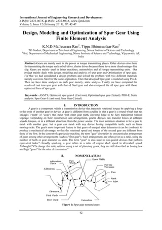
  • 1. International Journal of Engineering Research and Development e-ISSN: 2278-067X, p-ISSN: 2278-800X, www.ijerd.com Volume 5, Issue 12 (February 2013), PP. 42-47 Design, Modeling and Optimization of Spur Gear Using Finite Element Analysis K.N.D.Malleswara Rao1, Tippa Bhimasankar Rao2 1 PG Student, Department of Mechanical Engineering, Nimra Institute of Science and Technology 2 Hod, Department of Mechanical Engineering, Nimra Institute of Science and Technology, Vijayawada, AP, India Abstract:-Gears are mainly used in the power or torque transmitting places. Other devices also there for transmitting the torque such as belt drive, chains drives because those have more disadvantages like slip. Gears are mainly used in lathes machines, automobiles and all torque transmitting units. Our project mainly deals with design, modeling and analysis of spur gear and Optimization of spur gear. For that we had considered a design problem and solved the problem with two different materials namely cast-iron, Steel for the same application. Then that designed Spur gear is modeled using Pro-E. Then we have done analyses on each gear namely, static analysis. Finally we have compared the results of cast iron spur gear with that of Steel gear and also compared the all spur gear with those optimized form of spur gear. Keywords:- ANSYS, Optimized spur gear-1 (Cast iron), Optimized spur gear-2 (steel). PRO-E, Static analysis. Spur Gear-1 (cast iron), Spur Gear-2 (steel). I. INTRODUCTION A gear is a component within a transmission device that transmits rotational torque by applying a force to the teeth of another gear or device. A gear is different from a pulley in that a gear is a round wheel that has linkages ("teeth" or "cogs") that mesh with other gear teeth, allowing force to be fully transferred without slippage. Depending on their construction and arrangement, geared devices can transmit forces at different speeds, torques, or in a different direction, from the power source. The most common situation is for a gear to mesh with another gear, but a gear can mesh with any device having compatible teeth, such as linear moving racks. The gear's most important feature is that gears of unequal sizes (diameters) can be combined to produce a mechanical advantage, so that the rotational speed and torque of the second gear are different from those of the first. In the context of a particular machine, the term "gear" also refers to one particular arrangement of gears among other arrangements (such as "first gear"). Such arrangements are often given as a ratio, using the number of teeth or gear diameter as units. The term "gear" is also used in non-geared devices that perform equivalent tasks:"...broadly speaking, a gear refers to a ratio of engine shaft speed to driveshaft speed. Although CVTs change this ratio without using a set of planetary gears, they are still described as having low and high "gears" for the sake of convention." II. NOMENCLATURE Figure 1: Spur gear nomenclature 42
  • 2. Design, Modeling and Optimization of Spur Gear Using Finite Element Analysis III. COMMON ABBRIVATIONS OF SPUR GEAR  n. Rotational velocity. (Measured, for example, in r.p.m.)  ω Angular velocity. (Radians per unit time.) (1 r.p.m. = π/30 radians per second.)  N. Number of teeth. IV. TYPES OF GEARS Figure 2: Types of gears V. TOOTH PROFILE A profile is one side of a tooth in a cross section between the outside circle and the root circle. Usually a profile is the curve of intersection of a tooth surface and a plane or surface normal to the pitch surface, such as the transverse, normal, or axial plane. The fillet curve (root fillet) is the concave portion of the tooth profile where it joins the bottom of the tooth space. Figure 3: Tooth profile of spur gear VI. PITCH Pitch is the distance between a point on one tooth and the corresponding point on an adjacent tooth. It is a dimension measured along a line or curve in the transverse, normal, or axial directions. The use of the single word “pitch” without qualification may be ambiguous, and for this reason it is preferable to use specific designations such as transverse circular pitch, normal base pitch, and axial pitch. Figure 4: Pitch of spur gear Diametral pitch (transverse) is the ratio of the number of teeth to the standard pitch diameter in inches. 43
  • 3. Design, Modeling and Optimization of Spur Gear Using Finite Element Analysis  Normal diametral pitch, Pnd Normal diametral pitch is the value of diametral pitch in a normal plane of a helical gear or worm.  Angular pitch, θN, τ Angular pitch is the angle subtended by the circular pitch, usually expressed in radians. degrees or radians VII. DESIGN OF SPUR GEAR  Design of spur gear for following specifications: Dimensions of spur gear: Power to be transmitted: P = 20kw = 20000w Pinion speed: n1=1400rpm Gear ratio: I = 4 Gear speed = n2 = n1 / I Let the arrangement may be external gearing  Material selection: Now the material for pinion and gear Table 1: Material selection for spur gear & pinion Table 2: Dimensions of spur gear VIII. MODELING OF SPUR GEAR For modeling of a spur gear we used the PRO-ENGINEERING, it was developed by parametric technology corporation, USA and its latest version is PRO-E WILDFIRE.4 The RAM requirement for this software is 256MB and OS requirement to operate in WINDOWS 98/2000. Procedure of Modeling of spur gear in Pro-E:-  Start  All programs  PTC Pro-E Pro-E  Select the Part module and change the dimensions in to mm  Drawn the first base circle  Extruded the base circle up to required width  Select the sketch and select the surface of the base circle  Drawn the teeth and extruded up to the same width  By using pattern command in Pro-E generated the required number of teeth Figure 5: Spur gear model Figure 6 : Optimized spur gear model Figure 7 : Meshed Spur gear in ANSYS 44
  • 4. Design, Modeling and Optimization of Spur Gear Using Finite Element Analysis IX. ANALYSIS OF SPUR GEAR For doing analysis on the gear we used the ANSYS package, it is a general purpose finite element modeling package for numerically solving a wide variety of mechanical problems. Procedure of the analysis of the gear by using Ansys package:-  Start  All programs  Ansys 8.0  Ansys  Move the mechanical tool bar( for easy doing of the analysis)  Select the Ansys model i.e. static or modal , structural or thermal, and specify the dimensions that are used in the modeling, and give the analysis name  Move to setup mode to the model mode import the IGES file of that gear  Apply the material properties and mesh the object  After meshing move to the loads menu and constrain the inner circle that is lie on the shaft.  Apply the loads on the gear  Click on Solve now Seen the results. X. RESULTS  Spur gear-1:- Figure 8 : Stress intesity Figure 9 : Equivalent stress Figure 10 : Displaced shape  Optimized spur gear-1:- Figure 11 : Stress intesity Figure 12 : Equivalent stress Figure 13 : Displaced shape  Spur gear -2 :- Figure 14 : Stress intesity Figure 15 : Equivalent stress Figure 16 : Displaced shape 45
  • 5. Design, Modeling and Optimization of Spur Gear Using Finite Element Analysis  Optimized spur gear -2:- Figure 17 : Stress intesity Figure 18 : Equivalent stress Figure 19 : Displaced shape  Stress intensity at various nodes of spur gear-1 & optimized spur gear-1:- 1000 800 600 400 Gear 1 200 Gear Optimized 0 Nodes Nodes Nodes Nodes 1 4 7 10 Table 3 : Stress intensity at various nodes Figure 20 : Graph of Stress intensity at various nodes  Displacement at various nodes of spur gear-1 & optimized spur gear-1:- 8.00E-01 6.00E-01 4.00E-01 Gear 1 2.00E-01 0.00E+00 Optimized gear Table 4: Displacement at various nodes Figure 21 : Graph of displacement at various nodes  Stress intensity at various nodes of spur gear-2 & optimized spur gear-2:- 120 100 80 60 Gear 2 40 20 0 Gear 2 Node 10 optimized Node 1 Node 2 Node 3 Node 4 Node 5 Node 6 Node 7 Node 8 Node 9 Table 5: Stress intensity at various nodes Figure 22 : Graph of Stress intensity at various nodes 46
  • 6. Design, Modeling and Optimization of Spur Gear Using Finite Element Analysis  Displacement at various nodes of spur gear-2 & optimized spur gear-2:- 4.00E-03 2.00E-03 0.00E+00 Gear 2 Node 10 Node 1 Node 2 Node 3 Node 6 Node 7 Node 8 Node 4 Node 5 Node 9 -2.00E-03 -4.00E-03 Optimized -6.00E-03 gear-2 -8.00E-03 -1.00E-02 Table 6: Displacement at various nodes Figure 23 : Graph of Displacement at various nodes XI. CONCLUSION The design, modeling and analysis of spur gear & optimized spur gear are done. It is observed that the same required out put the dimensions of spur gear are various with respect to the material. And optimization of gear is also done on the same gears and computed the results and drawn the graphs for the results. The conclusion is that for the cast iron material the stress intensity and displaced shape results are better for actual spur gear compared to optimized spur gear as well as for the steel material the stress intensity and displaced shape results are nearly same for actual spur gear compared to optimized spur gear so by this i came to know that the optimization of spur gear may depends on change of materials. ACKNOELEDGMENT I would like to thank my Guide, Mr. Tippa Bhimasankar Rao for his time and support. In addition, I would like to thank my friends for sharing their experience in PRO-E, ANSYS. Finally, I would like to thank my family for their support and putting up with me for these past few months moral and financial support during my studies. REFERENCES [1]. Machine design by S.Md.Jalaludeen, Anuradha agencies. [2]. Machine design by R.K. Jain [3]. Machine design by „R.S. Kurmi‟ [4]. Design of machine elements by „Bandri‟ [5]. Machine design by R.K. Rajput [6]. Design data book by Md.jalaludeen [7]. Design data book by P.S.G. College [8]. . www.cs.cmu.edu/People/rapidproto/mechanisms/references.html [9]. Mechanical Engg design – Joseph E. Shigley. [10]. Design data book – P.S.G. College of technology. [11]. Design data book – K.Mahadevan & K.Balaveera Reddy. [12]. Analysis and approximation of contact problem By Mircea Sofonia and Weimin Hann [13]. Elastic contact analysis by boundary elements By Susumu Takahashi [14]. “A comprehensive analysis of fillet and contact stresses in straight spur gears” By M.A. Alfares 47