Ultralow-Power Low-Voltage Fully Differential Opamp
•
1 gefällt mir•301 views

This paper presents an ultralow-power operational amplifier (OpAmp) designed for long-life autonomous portable equipment. The OpAmp uses transistors biased in the subthreshold region to operate on a 0.8V supply with power consumption of only 1.2uW. Simulation results show it achieves 51dB open-loop gain, 57kHz unity-gain frequency, 60° phase margin, and 65dB common-mode rejection ratio for an 8pF load. The OpAmp is implemented in a 0.18um CMOS process and uses a fully differential design with a rail-to-rail input stage and class-AB output stage along with a common-mode feedforward circuit to remove common-mode input

Empfohlen
Empfohlen
Weitere ähnliche Inhalte
Was ist angesagt?
Was ist angesagt? (19)
Andere mochten auch
Ähnlich wie Ultralow-Power Low-Voltage Fully Differential Opamp
Ähnlich wie Ultralow-Power Low-Voltage Fully Differential Opamp (20)
Mehr von IJERD Editor
Mehr von IJERD Editor (20)
Kürzlich hochgeladen
Kürzlich hochgeladen (20)
Ultralow-Power Low-Voltage Fully Differential Opamp
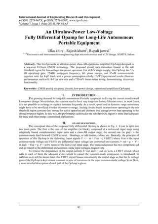
- 1. International Journal of Engineering Research and Development e-ISSN: 2278-067X, p-ISSN: 2278-800X, www.ijerd.com Volume 7, Issue 1 (May 2013), PP. 81-85 81 An Ultralow-Power Low-Voltage Fully Differential Opamp for Long-Life Autonomous Portable Equipment Ulka khire1 , Rajesh khatri2 , Rupali jarwal3 1, 2,3 Electronics and instrumentation engineering dept.microelectronics and VLSI design, SGSITS, Indore. Abstract:- This brief presents an ultralow-power class-AB operational amplifier (OpAmp) designed in a low-cost 0.18-μm CMOS technology. The proposed circuit uses transistors biased in the sub threshold region for low-voltage low-power operation. For a0.8-V single supply, this OpAmp has 51- dB open-loop gain, 57-kHz unity-gain frequency, 60◦ phase margin, and 65-dB common-mode rejection ratio for 8-pF loads with a power consumption ofonly1.2μW.Experimental results illustrate performances such as 0.14-V/μs slew rate and a 750-mV linear output swing, demonstrating its correct functionality. Keywords:- CMOS analog integrated circuits, low-power design, operational amplifiers (OpAmps). I. INTRODUCTION The growing demand for long-life autonomous Portable equipment is driving the current trend toward Low-power design. Nevertheless, the systems need to have very long-time battery lifetimes since, in most Cases, it is not possible to recharge or replace batteries frequently As a result, speed and/or dynamic range sometimes might have to be sacrificed in order to conserve energy Analog circuits based on transistors operating in the sub threshold region consume less energy for active operation and dissipate less leakage power than operating in the strong inversion region. In this way, the performance achieved in the sub threshold region is more than adequate for these and other energy-constrained applications. II. OPAMP DESCRIPTION The conceptual idea of the proposed fully differential OpAmp is shown in Fig. 1. It can be split into two main parts: The first is the core of the amplifier (in black), composed of a rail-to-rail input stage using adaptively biased complementary input pairs and a class-AB output stage; the second one (in gray) is the common-mode feed forward (CMFF) circuit. Headings, or add dashes, colons, etc. Basically, the principle of operation of this OpAmp is the following: Input signals V +/− in = Vcm •} Vdiff/2 (where Vcm is the input common-mode voltage and Vdiff is the differential input voltage) are converted into currents I+ out = g ・ V + in and I − Out = g .V − in by means of the rail-to-rail input stage. The transconductance has two components gd and gc related to the differential and common-mode input voltages, respectively. To remove the dependence of the output currents I+ out and I − out on Vcm, a CMFF circuit, which adds to each of them the adequate extra current to cancel the common-mode component, is introduced. In addition, as it will be shown later, this CMFF circuit biases conveniently the output stage so that the dc voltage gain of the OpAmp is kept almost constant in spite of variations in the input common-mode voltage Vcm. Next, a more detailed description of each part of the OpAmp is given.
- 2. An Ultralow-Power Low-Voltage Fully Differential Opamp for Long-Life… 82 Fig 1. Block dig of conceptual opamp TABLE 1 Transistor size M1,M2 20u M3 10u M4 40u M5,M8 12u M6,M7 14u M9,M10,M11,M12 15u M18,M17 50u M13,M16,M14,M15 60u Different blocks are:- 1) Rail-to-Rail Input Stage 2) Adaptive Bias Circuit 3) Class-AB Output Stage 4) CMFF Circuit
- 3. An Ultralow-Power Low-Voltage Fully Differential Opamp for Long-Life… 83 Fig 2. symbolic Schematic of opamp in cadence tool III. SIMULATION RESULTS The proposed OpAmp has been designed in a low-cost 0.18-μm CMOS technology with a 0.8-V single supply. The OpAmp was simulated using cadence virtuoso. Different blocks are designed in cadence tool and different types of closed and open loop analysis are being performed the simulation result of the OTA shows that the open loop gains of approximately 51 dB. The OTA has Unity Gain Frequency of about 57 MHz. The variation in CMRR is shown in figure 4. Figure 5 shows the Dc plot of This OTA. The simulated results of this OTA shows that PSRR of 80 dB and CMRR of 65 dB. Fig.3. closed loop differential gain (vout+)-(vout-)
- 4. An Ultralow-Power Low-Voltage Fully Differential Opamp for Long-Life… 84 Fig 4. CMRR plot of opamp Fig 5. Dc plot of opamp IV. CONCLUSIONS A simple and compact fully differential OpAmp has been presented focusing on the present-day increasing demand for low-cost severely energy-constrained system applications. To demonstrate the feasibility and scalability of the design, a standard 0.18-μm CMOS process with a very restrictive supply voltage of 0.8 V—instead of its nominal value of 1.8 V—has been used. The simulation and experimental results of a fabricated prototype have validated the predicted theoretical performances of the proposed OpAmp. Nevertheless, the authors are working to reduce the input offset voltage and to fix better the dc output voltage. A conclusion section must be included and should indicate clearly the advantages, limitations, and possible applications of the paper. Although a conclusion may review the main points of the paper, do not replicate the abstract as the conclusion. A conclusion might elaborate on the importance of the work or suggest applications and extension
- 5. An Ultralow-Power Low-Voltage Fully Differential Opamp for Long-Life… 85 ACKNOWLEDGMENT We would like to thank our college professors for supporting us .and providing us with such a nice and learning tool cadence. REFERENCES [1]. A. Wang, B. High smith, and A. P. Chandrakasan, Sub-Threshold Design for Ultra Low-Power Systems. New York: Springer-Verlag, 2010. [2]. K. de Langen and J. H. Huijsing, ―Compact low-voltage power-efficient Operational amplifier cells for VLSI,‖ IEEE J. Solid-State Circuits, vol. 33, no. 10, pp. 1482–1496, Oct. 1998. [3]. M. R. Valero, S. Celma, N. Medrano, B. Calvo, and C. Azcona, ―An ultra low-power low-voltage class AB CMOS fully differential OpAmp,‖ in Proc. IEEE ISCAS, Seoul, Korea, 2012. [4]. A. J. Lopez Martin, S. Baswa, J. Ramírez-Angulo, and R. González- Carvajal, ―Low-voltage super class AB CMOS OTA cells with very high Slew rate and power efficiency,‖ IEEE J. Solid-State Circuits, vol. 40, no. 5, pp. 1068–1077, May 2005. [5]. J.M. Carrillo, G. Torelli, M. A. Dominguez, R. Perez-Aloe, and J. Duque- Carrillo, ―A family of low- voltage bulk-driven CMOS continuous -time CMFB circuits,‖ IEEE Trans. Circuits Syst. II, Exp. Briefs, vol. 57, no. 11, pp. 863–867, Nov. 2011.