Welcome to International Journal of Engineering Research and Development (IJERD)

call for paper 2012, hard copy of journal, research paper publishing, where to publish research paper, journal publishing, how to publish research paper, Call For research paper, international journal, publishing a paper, IJERD, journal of science and technology, how to get a research paper published, publishing a paper, publishing of journal, publishing of research paper, reserach and review articles, IJERD Journal, How to publish your research paper, publish research paper, open access engineering journal, Engineering journal, Mathemetics journal, Physics journal, Chemistry journal, Computer Engineering, Computer Science journal, how to submit your paper, peer reviw journal, indexed journal, reserach and review articles, engineering journal, www.ijerd.com, research journals

Recommended
Recommended
More Related Content
What's hot
What's hot (19)
Viewers also liked
Viewers also liked (10)
Similar to Welcome to International Journal of Engineering Research and Development (IJERD)
Similar to Welcome to International Journal of Engineering Research and Development (IJERD) (20)
More from IJERD Editor
More from IJERD Editor (20)
Welcome to International Journal of Engineering Research and Development (IJERD)
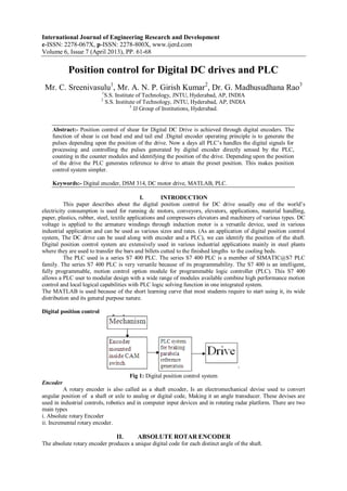
- 1. International Journal of Engineering Research and Development e-ISSN: 2278-067X, p-ISSN: 2278-800X, www.ijerd.com Volume 6, Issue 7 (April 2013), PP. 61-68 Position control for Digital DC drives and PLC Mr. C. Sreenivasulu1 , Mr. A. N. P. Girish Kumar2 , Dr. G. Madhusudhana Rao3 1 S.S. Institute of Technology, JNTU, Hyderabad, AP, INDIA 2 S.S. Institute of Technology, JNTU, Hyderabad, AP, INDIA 3 JJ Group of Institutions, Hyderabad. Abstract:- Position control of shear for Digital DC Drive is achieved through digital encoders. The function of shear is cut head end and tail end .Digital encoder operating principle is to generate the pulses depending upon the position of the drive. Now a days all PLC’s handles the digital signals for processing and controlling the pulses generated by digital encoder directly sensed by the PLC, counting in the counter modules and identifying the position of the drive. Depending upon the position of the drive the PLC generates reference to drive to attain the preset position. This makes position control system simpler. Keywords:- Digital encoder, DSM 314, DC motor drive, MATLAB, PLC. I. INTRODUCTION This paper describes about the digital position control for DC drive usually one of the world’s electricity consumption is used for running dc motors, conveyors, elevators, applications, material handling, paper, plastics, rubber, steel, textile applications and compressors elevators and machinery of various types. DC voltage is applied to the armature windings through induction motor is a versatile device, used in various industrial application and can be used as various sizes and rates. (As an application of digital position control system, The DC drive can be used along with encoder and a PLC), we can identify the position of the shaft. Digital position control system are extensively used in various industrial applications mainly in steel plants where they are used to transfer the bars and billets cutted to the finished lengths to the cooling beds. The PLC used is a series S7 400 PLC. The series S7 400 PLC is a member of SIMATIC@S7 PLC family. The series S7 400 PLC is very versatile because of its programmability. The S7 400 is an intelligent, fully programmable, motion control option module for programmable logic controller (PLC). This S7 400 allows a PLC user to modular design with a wide range of modules available combine high performance motion control and local logical capabilities with PLC logic solving function in one integrated system. The MATLAB is used because of the short learning curve that most students require to start using it, its wide distribution and its general purpose nature. Digital position control Fig 1: Digital position control system Encoder A rotary encoder is also called as a shaft encoder, Is an electromechanical devise used to convert angular position of a shaft or axle to analog or digital code, Making it an angle transducer. These devises are used in industrial controls, robotics and in computer input devices and in rotating radar platform. There are two main types i. Absolute rotary Encoder ii. Incremental rotary encoder. II. ABSOLUTE ROTAR ENCODER The absolute rotary encoder produces a unique digital code for each distinct angle of the shaft.
- 2. Position control for Digital DC drives and PLC 62 Fig2: Absolute rotary encoder A. Drives An electrical motor together with its control equipment and energy transmitting device forms an electric drive. Normally in industries where speed variation and control are desired ,a separately excited type dc motors is used where instead of connecting armature and field parallel (as in case of a shunt motor) they are separately excited by separate sources.. A row of sliding contacts is fixed to a stationary object so that each metal has been cut out. The metal sheet is connected to a source of electric current, and each contact is connected to a separate electrical sensor. The metal pattern is designed so that each possible position of the axle creates a unique binary code in which some of the contacts are connected to the current source (i.e. switched on) and others are not (i.e. switched off). B. Drive Operation and Control The DC Drives simplicity, ease application, reliability backbone of industrial applications. A typical adjustable speed drive using a silicon control rectifier (SCR) power conversion .The SCR converts the fixed voltage alternating current (AC) of the power source to an adjustable voltage, controlled direct current (DC) output which is applied to the armature of a DC motor. A light source and photo detector array reads the optical pattern that result from the disc's position at any one time. This code can be read by a controlling device, such as a microprocessor, to determine the angle of the shaft. The SCR’ s provide a controllable power output by "phase angle control", so called because the firing angle (a point in time where the SCR is triggered into conduction) is synchronized with the phase rotation of the AC power source. The effect is similar to a very high speed switch, capable of being turned on and "conducted" off at an infinite number of points within each half cycle. This occurs at a rate of 50 times a second on a 50 Hz line, to deliver a precise amount of power to the motor. The efficiency of this form of power control is extremely high since a very small amount of triggering energy can enable the SCR (Silicon Controlled Rectifier) to control a great deal of output power. DC Drive Control System generally contains a drive controller and DC motor the controls allow the operator to start, stop, and change the direction and speed of the motor by tuning potentiometers or other operator devices. These controls may be an integral part of the Controller or may be remotely mounted. The drive controller converts a 3-phase AC voltage to an adjustable DC voltage, which is then applied to a DC motor armature. Motor shaft rotation and direction are proportional to the magnitude and polarity of the DC voltage applied to the motor. .The tachometer (feedback device) shown in Figure converts actual speed to an electrical Signal that is summed with the desired reference signal. The output of the summing junction provides an error signal to the controller and a speed correction is made. A general statement can be made that for PM and Shunt Wound motors load torque determines armature current. In summary, two general statements can be made relative to DC motor performance. Motor Speed is primarily determined by Applied Armature Voltage. Motor Torque is controlled by Armature Current Fig3: Standard binary encoding
- 3. Position control for Digital DC drives and PLC 63 Rotary encoder for angle-measuring devices marked in 3-bit binary .The inner ring corresponds to Contact 1 in the table. Black sectors are "on". Zero degrees is on the right-hand side, with angle increasing counter clockwise. An example of a binary code, in an extremely simplified encoder with only three contacts, is shown below. Standard Binary Encoding Sector Contact 1 Contact 2 Contact 3 Angle 1 Off Off Off 0° to 45° 2 Off Off On 45° to 90° 3 Off On Off 90° to 135° 4 Off On On 135° to 180° 5 On Off Off 180° to 225° 6 On Off On 225° to 270° 7 On On Off 270° to 315° 8 On On On 315° to 360° In general, where there are n contacts, the number of distinct positions of the shaft is 2n . In this example, n is 3, so there are 2³ or 8 positions. In the above example, the contacts produce a standard binary count as the disc rotates. However, this has the drawback that if the disc stops between two adjacent sectors, or the contacts are not perfectly aligned, it can be impossible to determine the angle of the shaft. To illustrate this problem, consider what happens when the shaft angle changes from 179.9° to 180.1° (from sector 4 to sector 5). At some instant, according to the above table, the contact pattern will change from off-on-on to on-off-off. However, this is not what happens in reality. In a practical device, the contacts are never perfectly aligned, and so each one will switch at a different moment. If contact 1 switches first, followed by contact 3 and then contact 2, for example, the actual sequence of codes will be Off-on-on (starting position) On-on-on (first, contact 1 switches on) On-on-off (next, contact 3 switches off) On-off-off (finally, contact 2 switches off) Now look at the sectors corresponding to these codes in the table. In order, they are 4, 8, 7 and then 5. So, from the sequence of codes produced, the shaft appears to have jumped from sector 4 to sector 8, and then gone backwards to sector 7, then backwards again to sector 5, which is where we expected to find it. In many situations, this behaviour is undesirable and could cause the system to fail. For example, if the encoder were used in a robot arm, the controller would think that the arm was in the wrong position, and try to correct the error by turning it through 180°, perhaps causing damage to the arm. Fig 4 : speed control of dc drive A tachometer is used when a more accurate measurement of speed is needed, or when the motor will be operated above base speed. A measurement of actual speed is returned to the speed controller. The speed controller will make armature voltage adjustments to maintain constant speed with variations in load. If, for example, load is suddenly increased the motor will slow, reducing speed feedback. The speed controller will output a higher signal to the current controller, which will increase the firing angle of the firing
- 4. Position control for Digital DC drives and PLC 64 circuit. The resulting increased armature voltage applies more torque to the motor to offset the increased load. Motor speed will increase until it is equal with the speed reference set point. When the motor is rotating faster than desired speed armature voltage is reduced. In a four-quad drive DC armature voltage could momentarily be reversed to slow the motor at a faster rate to the desired speed. The drive monitors current, which is summed with the speed control signal at the current controller. The drive acts to maintain current at or below rated current by reducing armature voltage if necessary. This results in a corresponding reduction in speed until the cause of the over current is removed. Some applications require the motor to operate with a specific torque regardless of speed. The outer loop (speed feedback) is removed and a torque reference is input. The current controller is effectively a torque controller because torque is directly proportional to current. Major Problems with analog drives The control system performs the following function Speed regulation of drive. Start/Stop and Trip sequence logic Alarms/Annunciation of faults This system is having following limitations. Components misbehaviour Usages of active/passive components are prone to aging and temperature sensitive .Frequent break down/Loss of production system is sensitive to voltage fluctuations resulting in loss of production Fault diagnosis/trouble shooting Difficulties in accurate fault diagnostics in case of breakdown Multiple settings necessary while replacing spare cards which increase shutdown time Availability of spares support Costs of analog system spares are very high Non-availability of spares due to obsolescence hence maintaining the stock of spares in an operating condition Maintenance cost high. Technology outdated number of cards to realize the functions are more. 6RA70 Series Microprocessor-Based Converters from 6kW to 2500Kw for Variable- speed DC Drives.. Applications Series 6RA70 SIMOREG DC MASTER Converters are fully digital, compact units for three-phase supply which supply the armature and field of variable-speed DC drives with rated armature currents of between 15A and 3000A.The field circuit can be supplied with currents of up to 85A (current levels depend on the armature rated current). Advantages Drives are not tripping during power dip on over current as the drive control action is very fast. Large voltage and frequency variation range resulting in reduced fuse failure compared to the Analog drive system Ease of maintenance due to fewer cards and lesser amount of wiring. No drift in components (op. amps.) which is present in Analog system resulting in consistent performance. Being a digital system, security of parameter settings is ensured. . III. INCREMENTAL ROTARY ENCODER An incremental rotary encoder, also known as a quadrature encoder or a relative rotary encoder, has two outputs called quadrature outputs. They can be either mechanical or optical. In the optical type there are two gray coded tracks, while the mechanical type has two contacts that are actuated by cams on the rotating shaft. The mechanical type requires de bouncing are typically used as digital potentiometers on equipment including consumer devices. Most modern home and car stereos use mechanical rotary encoders for volume. Due to the fact the mechanical switches require debouching, the mechanical type are limited in the rotational speeds they can handle. The incremental rotary encoder is the most widely used of all rotary encoders due to its low cost: only two sensors are required. The fact that incremental encoders use only two sensors does not compromise their accuracy. One can find in the market incremental encoders with up to 10,000 counts per revolution, or more. There can be an optional third output: reference, which happens once every turn. This is used when there is the need of an absolute reference, such as positioning systems. The optical type is used when higher RPMs are encountered or a higher degree of precision is required. Incremental encoders are used to track motion and can be used to determine position and velocity. This can be either linear or rotary motion. Because the direction can be determined, very accurate measurements can be made. They employ two outputs called A & B which are called quadrate outputs as they are 90 degrees out of phase. Fig 5: Two square waves in quadrate (clockwise rotation). The state diagrams.
- 5. Position control for Digital DC drives and PLC 65 Coding for clockwise rotation Phase A B 1 0 0 2 0 1 3 1 1 4 1 0 The output waveforms are 90 degrees out of phase, which is all that the quadrature term means. These signals are decoded to produce a count up pulse or a count down pulse. For decoding in software, the A & B outputs are read by software, either via an interrupt on any edge or polling, and the above table is used to decode the direction. For example if the last value was 00 and the current value is 01, the device has moved one half step in the clockwise direction. The mechanical types would be de bounced first by requiring that the same (valid) value be read a certain number of times before recognizing a state change. These systems with rotary axis settings of closed loop control. This is electrically connected to the cu. Zero pulse are transferred from the encoder emulation of shear. If the encoder is turning too fast, an invalid transition may occur, such as 00->11. There is no way to know which way the encoder turned; if it was 00->01->11, or 00->10->11. VI. PROGRAMMABLE LOGIC CONTROLLER The PLC acts as an interface between the drive and encoder. Programmable Logic Controllers(PLC) is an intelligent system of modules, which performs discrete or continuous logic, that was introduced in the control and instrumentation industry for replacing relay based logic .PLC’s were initially called programmable controllers(PC).this caused a small confusion when personal computer appeared. To avoid confusion a designation PC was left to computers, and programmable controllers became programmable logic controllers. PC or PLC was first developed for general motors corporation in 1968 to eliminate costly scrapping of assembly line relays during model change over. By 1971 PC’s were being used in applications outside automotive industry. First PLC controllers were simple devices. They connected inputs such as switches, digital sensors etc., and based on internal logic they turned output devices on or off. As they were capable of on or off control, only their application was limited to machines and processes that required inter locking and sequencing applications.Todays PLC’s can handle highly complex tasks such as position control, various regulation and other complex applications. The speed of work and easiness of programming were also improved. In addition, modules for special purposes were developed. A programmable logic controller (PLC) or programmable controller is a digital computer used for automation of electromechanical processes, such as control of machinery on factory assembly lines, control of amusement rides, or control of lighting fixtures. PLCs are used in many different industries and machines such as packaging and semiconductor machines. Unlike general-purpose computers, the PLC is designed for multiple inputs and output arrangements, extended temperature ranges. Programs to components and developing an appropriate program, the PLC can be used for an almost unlimited variety of applications. The DSM314 is an intelligent, fully programmable, motion control option module for the Series90-30 Programmable Logic Controller (PLC). The DSM314 allows a PLC user to combine high performance motion control and Local Logic capabilities with PLC logic. i. Features of the Motion Mate DSM314 - High Performance - Digital Signal Processor (DSP) control of GE Fanuc servos - Block Processing time under 5 milliseconds Coding for counter-clockwise rotation Phase A B 1 1 0 2 1 1 3 0 1 4 0 0
- 6. Position control for Digital DC drives and PLC 66 - High resolution of programming units - Position: -536,870,912...+536,870,911 User Units - Velocity: 1 ... 8,388,607 User Units/sec - Acceleration: 1 … 1,073,741,823 User Units/sec/sec - Easy to Use The DSM314 and Series S7 400 PLC operate together as one integrated motion control package. The DSM314 communicates with the PLC through the backplane interface. A motion program consists of a group of user-programmed motion command statements that are stored to and executed in the DSM314. The DSM314 executes motion program commands sequentially in a block-by- block fashion once a program is selected to run. The motion program is executed autonomously from the PLC, although the PLC starts the DSM314 motion program and can interface with it (with parameters and certain commands) during execution. In addition, external inputs (CTL bits) connected directly to the DSM314 faceplate or controlled by Local Logic can be used in motion programs to delay or alter program execution flow. The PLC receives status information (such as position, velocity, and Command Block Number) from the DSM314 during program execution. Motion programs 1-10 and subroutines 1-40 are created using Versa Pro 1.1 (or later) PLC programming software and are stored along with the modules. Motion Program Command Types The motion program commands are grouped into four categories: Type 1 Commands . CALL (Subroutine) . JUMP Type 2 Commands . Block number . SYNC (Block Synchronization) . LOAD (Parameter) . ACCEL (Acceleration) . VELOC (Velocity) Type 3 Commands . PMOVE (Positioning Move) . CMOVE (Continuous Move) . DWELL . WAIT Program/Subroutine Definition Commands . PROGRAM . ENDPROG . SUBROUTINE . ENDSUB Type 1 commands can redirect the program path execution, but do not directly affect positioning. Call (Subroutine) executes a subroutine before returning execution to the next command. Jumps may be conditional or unconditional. An unconditional jump always redirects execution to a specified program location. Type 2 commands also do not affect position. Block numbers provide identification or label for the Type 3 command that follows. -Block numbers are required with JUMP commands; otherwise, they are optional. The SYNC (synchronize block) command is a two-axis synchronization command. The Load Parameter command allows the user to load a value into a parameter register. Type 3 commands start or stop motion and thus affect positioning control. Positioning (PMOVE) and Continuous (CMOVE) moves command motion. -The Dwell, Wait, and End of Program commands stop motion. Example ACCEL 1000 VELOC 2000 PMOVE 5000, ABS, LINEAR
- 7. Position control for Digital DC drives and PLC 67 This example shows how simple PMOVEs and CMOVEs combine to form motion profiles. VELOC 1200 PMOVE 10000, ABS, S-CURVE ACCEL 1500 VELOC 2800 CMOVE 6000, INCR, LINEAR VELOC 1200 CMOVE 23000, ABS, S-CURVE ACCEL 1000 VELOC 2800 PMOVE 5000, INCR, LINEAR In digital system, the pulses generated by encoder are directly sensed by the PLC, counted in the counter modules and the position of the drive is identified. Depending upon the position of the drive PLC generates the reference to the drive to attain the preset position. V. RESULTS Fig 6: Head cutting pulse Fig 7: tail cutting pulse VI. CONCLUSION The new digital position control system consists of very few elements and is supported by the manufacturers. The latest hardware is reliable, consumes less power and failures are less. All the required tuning is possible through software changes and most of the time without shutdown of the equipment such changes can be made online. The position control accuracy is high with digital control system and very easy to diagnose in case of problem in the rolling process in industries. The DSM module which is envisaged for the position control can access 4 independent drives and thus the number of hardware requirement has reduced to a great extent. ACKNOWLEDGMENT Firstly the author would like to thank his parents for their best wishes to join Postgraduate Program. Special thanks to my guide Mr.M.Venkateswara rao, Associate Professor, Electrical Engineering Department,GMRIT,Rajam,A.P. for his valuable guidance to prepare this paper.The author greatly expresses his
- 8. Position control for Digital DC drives and PLC 68 thanks to Mr. TSLV .Ayya Rao, Assistant Professor, Electrical Engineering Department, GMRIT, Rajam, A.P. for his concern to support in preparing this paper. REFERENCES [1] Steven T.Karris, ‘Introduction to matlab with Engineering Applications’, Orchard Publications. [2] Tan Kiong Howe, May 2003, Thesis, B.E (Hons), ‘Evaluation of the transient response of an Induction motor using MATLAB/SIMULINK’, University of Queensland. [3] E.H.Miller, 2000, Introduction to induction motor Drives. [4] Carnegie, D.etal, 2004, ‘Encoders and its applications’, University of Waikato, Hamilton, New Zealand. BIOGRAPHY 1 Mr.C.Sreenivasulu, Associate Professor in S.S. Institute of Technology in the Department of Electrical and Electronics Engineering, AP, Hyderabad. He received his M.Tech & B.Tech from Sri Venkateswara University, Tirupati, AP, INDIA. Both in Electrical and Electronics Engineering. His research interests are power system operation and control, power system stability and new type of A.C transmission system. 2 Mr.A.N.P.Girish Kumar, Assistant Professor S.S. Institute of Technology in the Department of Electrical and Electronics Engineering, AP, Hyderabad. He received his M.Tech from JNT University Hyderabad & B.Tech from Andhra University Vishakhapatnam, AP, INDIA. Both in Electrical and Electronics Engineering. His interested are power Electronics Drives Operation and control, Machine Modelling. 3 Dr.G.Madhusudhana Rao, Professor in JJ Group of Institutions, Hyderabad. PhD from JNT University Hyderabad and completed M.Tech from JNT University-Hyderabad, INDIA. He has Published 13 research papers in International Journals and more than 15 International conference papers and more than 10 national conference papers.