SlideShare ist ein Scribd-Unternehmen logo
1 von 74
Downloaden Sie, um offline zu lesen


Practical Source Code for 
Ship Motions Time Domain Numerical Analysis 
and Its Mobile Device Application 
 
Master of Science Thesis in the Master Degree Programme, Naval Architecture 
 
ZAYAR THEIN 
Department of Shipping and Marine Technology 
CHALMERS UNIVERSITY OF TECHNOLOGY 
Göteborg, Sweden, 2011 
Report No. X‐11/273   
i
Practical Source Code for
Ship Motions Time Domain Numerical Analysis
and Its Mobile Device Application
Zayar Thein
Department of Shipping and Marine Technology
CHALMERS UNIVERISTY OF TECHNOLOGY
Göteborg, Sweden 2011
ii
Practical Source Code for Ship Motions Time Domain Numerical
Analysis and Its Mobile Device Application
Zayar Thein
Report No X-11/273
Department of Shipping and Marine Technology
CHALMERS UNIVERSITY OF TECHNOLOGY
SE-412 96 Göteborg
Sweden
iii
Abstract
This thesis included developing MATLAB program source code for the six degrees of rigid
body freedom time domain motions of a ship travelling with a specified mean velocity in
waves. The code is developed to simulate canonical forced and free motions. This study
followed the impulse-response function time domain method in which the hydrodynamic
coefficients are computed using the 2-D linear strip method in the frequency domain and
converted into the time domain. The equations of motion are then solved simultaneously.
This study considers merchant ships except for ships with a buttock flow stern. Ikeda’s
prediction is used for roll damping computation, and a good solution is achieved for vessels
other than buttock flow stern ships in roll motion. A range of wave periods and speeds are
also considered. Steady-state results are compared to other published results. The numerical
method agrees with classical ship motions and published results.
The present work explores ways to simulate ship motion in mobile devices. Two concepts
are proposed: web-based simulation (WBS) and a stand-alone simulation. The latter
approach is adopted. Two parts of the source codes are rewritten for the iOS platform: the
motion related to memory forces and the calculation engine. The codes are tested in the iOS
simulator, and the results are compared with the MATLAB solution. The world’s first mobile
device application in naval architecture achieves a good simulation result.
iv
Acknowledgements
This work was made possible by the support of many people. First, the project could never
have been completed without the remarkable support, effort, and motivation of Professor
Carl-Erik Janson, my supervisor at Chalmers University of Technology, and Martin
Schreuder, the examiner of my thesis. To them, I owe an enormous debt of gratitude.
The previous work of Benjamin Gros and Luis Felipe Sánchez Heres on the frequency
domain part and Erik Ovegård’s numerical simulation of parametric rolling served as an
invaluable guide, which undoubtedly helped me to avoid wrong turns and poor decisions in
my quest to solve many problems. Special thanks to Professor Lars Bergdahl, who
stimulated my interest in seakeeping. My mentor, Professor Alaa Mansour inspired me to
become a naval architect. I offer him my sincere gratitude.
I thank Lotta Olsson, the Studieadminstratör, for her kind assistance throughout my study at
Chalmers. Thank you also to Dr. Ken Worthy for his tireless reviewing of my drafts. Finally,
my family, friends, and co-workers at Herbert-ABS also supported me throughout the project.
v
Table of contents
Abstract ...................................................................................................................................................iii
Acknowledgements.................................................................................................................................iv
Abbreviations .......................................................................................................................................... 1
1. Introduction..................................................................................................................................... 4
1.1. Overview.................................................................................................................................. 4
1.2. Project Description.................................................................................................................. 4
1.3. Ship Motions............................................................................................................................ 5
1.4. Summary.................................................................................................................................. 7
2. Background Theory.......................................................................................................................... 8
2.1. Overview.................................................................................................................................. 8
2.2. Equations of Motion in Time Domain ..................................................................................... 8
2.3. Components of Time Domain Motion Equations.................................................................. 10
2.3.1. Radiation Forces............................................................................................................ 10
2.3.2. Restoring and Froude-Krylov Forces ............................................................................. 11
2.3.3. Diffraction Forces .......................................................................................................... 12
2.3.4. Viscous Damping Force in Roll Motion.......................................................................... 12
2.4. Computing Hydrodynamic Coefficients................................................................................. 13
2.5. Numerical Method ................................................................................................................ 14
2.6. Error Assessments and Numerical Stability........................................................................... 15
2.7. Summary................................................................................................................................ 16
3. Source Code Development and Software Implementation .......................................................... 17
3.1. Overview................................................................................................................................ 17
3.2. Development of MATLAB Source Code................................................................................. 17
3.2.1. Development of MATLAB User Interface ...................................................................... 18
3.2.2. Establishing Reference Systems .................................................................................... 20
3.2.3. Computing Froude-Krylov Forces.................................................................................. 21
vi
3.2.4. Mathematical Model..................................................................................................... 22
3.3. Mobile Device Software Implementation ............................................................................. 23
3.3.1. Architecture................................................................................................................... 23
3.3.2. Development Environment ........................................................................................... 24
3.4. Summary................................................................................................................................ 26
4. Results, Validation, and Discussion ............................................................................................... 27
4.1. Overview................................................................................................................................ 27
4.2. Box Ship Validation................................................................................................................ 27
4.3. Validation of Adopted Methods............................................................................................ 29
4.4. Validation and Numerical Results for the S175..................................................................... 30
4.5. Discussion.............................................................................................................................. 37
5. Conclusions.................................................................................................................................... 38
6. References..................................................................................................................................... 40
Appendix A: Supplementary Notes in Computing Restoring and Excitation Forces ..................... 42
Appendix B: Basic Formulae for Viscous Damping Computation.................................................. 44
Appendix C: Determining Added Mass and Damping Coefficients of a Ship ................................ 49
Appendix D: Big Time Tutorials ..................................................................................................... 59
Appendix E: Programming Guide.................................................................................................. 66
1
Abbreviations
aij: Sectional added mass
aw: Wave amplitude
a2n-1: Mapping coefficient
A: Added mass matrix
As: Cross section area
: Sectional damping coefficient
Bij: Inviscid damping matrix
B: Beam at waterline
BF
: Hull skin friction damping coefficient
BE
: Hull eddy shedding damping coefficient
Bw
: Free surface wave damping coefficient
Bl
: Lift force damping coefficient
Cij: Stiffness coefficients matrix
Cb : Block coefficient
Cw : Wave celerity
d: Water depth
fi
I
: Sectional Froude-Kryov force for the i-th motion
fi
D
: Sectional Diffraction force for the i-th motion
F : Force vector
Fe : Exciting forces vector
Fn: Froude number
Fb : Freeboard
g: Earth’s gravity
GMt, GMl: Transverse and longitudinal metacentric height
H0: Half the beam draft ratio.
I4: Roll moment of inertia
2
I5: Pitch moment of inertia
j: Index of six degrees of freedom
k: Wave number
K: Retardation Function
kxx: Roll radius of gyration
kyy: Pitch radius of gyration
l: Euclidian length
LCG: Longitudinal centre of gravity
LOA: Length over all
LWL: Length of waterline
: Unit vector
: Number of angular frequency steps
: Number of time steps
Ms: Conformal mapping scale factor
OG: Vertical distance between the water line and the center of gravity, OG=D-KG
P: Pressure
̂: Position Vector
Re: Effective bilge radius
U: Vessel speed
VCG, KG: Vertical centre of gravity
VCB: Vertical centre of buoyancy
vo: Threshold velocity
V: Displaced Volume
∇ : Displacement
ξ: Wave elevation
ω: Angular frequency
Ω: Angular frequency Maximum value in lieu of infinity in computation
Δ : Time step
Γ: Maximum time limit in lieu of infinity in computation
3
ωe: Encounter frequency
β: Heading angle
ε: Phase angle
λ: Wave length
ηi: i-th wave motion
ηc: Complex amplitude of the wave motion
ν: Kinematic viscosity of the water
: Velocity potential
σs: Sectional area coefficient
: Density of water
4
1. Introduction
1.1. Overview
The study of wave-induced loads and motions of ships is important both in ship design and
operational studies. To assess these loads and motions, model test, full-scale trials, or
numerical calculations may be used. Although full-scale trials provide the most realistic
results, they may not work well for testing extreme weather conditions, which are infrequent.
Model tests also create difficulties in scaling the test results when viscous hydrodynamic
forces are considered. [4] On the other hand, the growing computational capacity of modern
computers and the ease of carrying out simulated tests allow numerical computations to play
an increasingly important role. More advanced and easy to use computer aided engineering
software products are needed for naval architecture work, including analysis of ship motions.
Based on different approaches to solutions, the numerical technique in ship motion analysis
can be categorized as frequency domain and time domain methods. The latter approach is
still under development at industries and institutions, including at the Shipping and Marine
Technology Department of Chalmers University of Technology. For research and educational
purposes, computational source codes are written in MATLAB, a high-level technical
computing language, at Charmers University. On the other hand, the current shift taking
place in the computer industry from personal computers to mobile devices demands touch-
screen based computer programs and mobile device applications. Unlike other
computations, the numerical time domain method requires longer computing time and more
computer resources.
The purpose of this study is to develop a MATLAB source code based on the time domain
method, which can be used to analyze ship motion and to investigate whether the method
can be implemented in current mobile devices.
Section 2 of this document formulates the mathematical descriptions for the equations of
motion in the time domain as well as the dynamic balance of inertial, hydrostatic (i.e.
gravitational), and hydrodynamic forces acting upon a ship’s hull. It also describes the
numerical implementation of equations of motion and methods to analyze errors generated
by numerical calculations.
Section 3 presents the MATLAB source code development as well as an application for
mobile devices.
Section 4 illustrates results for two hull forms with zero speed. The conventional ship S-175
and a box-shaped hull are examined. Forced periodic motion results are compared to
available published results.
Section 5 discusses the contributions of this work and its practical applications. It highlights
the advantages and disadvantages of this program as well as its limitations. It also highlights
important issues for future research.
1.2. Project Description
In addition to time domain numerical computation, the ship motion simulation source code
that the present work seeks to develop requires knowledge of the seakeeping properties of
5
the vessel under study. Moreover, the program must be capable of reading ship geometry
files so that the study can be done on different ship models. Furthermore, the program
should include a graphical user interface for easy entering and editing of data and viewing of
results. These requirements are listed in Table 1 as a program development sequence.
Table 1: Program Development Sequence
Sequence Description
Entering Data
To be able to upload ship geometry files, enter computational
data, and select user options, a MATLAB graphical user
interface will be developed.
Analyzing the Ship Model
Time domain computation requires ship model data. The
program will calculate ship hull model data and hydrostatic
properties from the corresponding geometry file.
Computing Coefficients
Hydrodynamics coefficients are required in computing motion
equations and are based on ship geometry, wave frequency,
and ship speed. These coefficients will be computed before
solving the motion equation numerically.
Computing Forces
Linear and non-linear forces required by the time-domain
method will be solved numerically.
Solving Motion Equation
Numerical method will be developed and the motion equations
will be solved numerically in all rigid body degrees of freedom.
Viewing the Results
The same MATLAB user interface will be developed so that the
user will be able to easily access the result of the time domain
numerical computation.
Migrating to a Mobile
The MATLAB source code will be rewritten in Xcodes for the
Apple Mobile iOS platform.
To simplify reading the geometry file and solving the motion equation, the program will be
limited to analyzing motion on ships. Offshore structures, such as semi-submersible, tension
leg platforms, and Jack-up drilling rig, will not be handled by the program. In addition, the hull
should be a mono hull, and no roll tank will be considered.
1.3. Ship Motions
Although a ship operates on a two-dimensional sea surface, due to wave induced loads, six
rigid body degrees of freedom—surge, sway, heave, roll, pitch, and yaw—about a reference
frame (oxyz), fixed to the steady motion of the ship, are considered for the motion of a ship,
as shown in figure 1. The vessel floats freely and travels at constant forward speed U and
rotation, , with respect to an inertial frame which will be described in section 3. These six
6
Direction of wave propagation,
(360 ° to be considered)
Sway,
Pitch,
Heave,
Yaw,
oscillation motions at a given time, ship geometry, and speed, and wave definition are
determined in a ship motion study.
Figure 1: Definitions of coordinate system and rigid-body motion modes. U is the forward
speed for the ship. Wave propagation direction may be varied.
To compute the response of a vessel to waves, the equations of motion are solved. In the
simple case of a monochromatic incident wave, the equations might appear as
∑ [ + + + ] = ∑ for i=1,…,6 … (1)
where, is the position of the body, Mij are the elements of the generalized mass matrix, Aij
are the elements of the hydrodynamic mass or added mass matrix, Bij are the hydrodynamic
damping or radiation damping coefficients, Cij are the hydrostatic stiffness or restoring
coefficients, and ∑ represents the resultant of all other forces in the i direction (i.e. those in
addition to the wave exciting force and hydrodynamic reaction forces) that may be present. A
dot indicates a derivative with respect to time. Once the above quantities have been found,
the motion of the ship in waves can be predicted by solving the equations of motion.
When solving the equations of motion, one may use either the frequency domain method or
the time domain method. In the frequency domain, the ship's motions are treated as low
amplitude sinusoidal motions. The calculation is fast since the computation is done in one
step for a particular frequency response. It can produce usable results. However, the method
should not be used if the Froude number is too high and the vessel of interest is not
sufficiently slender (i.e. the ratio between the breadth and draft is larger than 6). [2] On the
other hand, the time domain method is popular when very large ships are considered. [7] The
downside is that the method itself is complex and more computationally intensive. It requires
many thousands of small incremental time steps in computations. Figure 2 illustrates the
relationship between a time domain solution of waves and a frequency domain
representation of the waves by a wave spectrum.
Surge, Roll,
Ship speed,
7
Figure 2: The relation between a frequency domain and time domain solutions.
1.4. Summary
The purpose of this work, then, is to develop open source MATLAB code for the time domain
numerical method for ship motion analysis. First, ways to compute ship hydrostatic
properties, hydrodynamic coefficients, and required forces in the equations of motion will be
sought. Then, the code to solve the equations will be developed. The equations are solved
and verified with other results predicated by other institutions. Finally, the mobile device
application will be developed based on MATLAB codes, and the application will be tested to
determine whether it is feasible for seakeeping study.
Frequency
Domain
Time Domain
Sum
Random Wave
Elevation
Wave Spectrum
Regular wave components with
Random Phase Angles
8
2. Background Theory
2.1. Overview
This section establishes the theoretical background of the source code developed in this
project and highlights the solution methods used to achieve reliable results. The section has
three parts. The first part is concerned with setting up the equations of motion for the time
domain method. The second part outlines each element of the equations. The last part
provides ways to solve the equations numerically.
2.2. Equations of Motion in Time Domain
When establishing the ship motion equations, Newton’s Second Law of Motion may be used
as a basic. In general, a ship’s equations of motion might appear as
( ) = ∑ … (2)
where, M is the mass of the ship, is the acceleration of the ship, and ∑ on the right hand
side of the equation is the sum of all applied forces from waves which causes the response
of the untethered ship as described on the left hand side. The task now is to identify the
forces on the ship.
The wave forces on the ship may be categorized into two parts: viscous forces from drag and
inertia forces, as indicated by potential flow wave theory. In this seakeeping project, inertial
forces are more important than drag forces and will only be considered in the force
equilibrium described in equation 2. The inertia forces can be identified by considering a
spectrum of waves interacting with the ship. One of the components of the spectrum consists
of waves that will diffract upon the ship hull and scatter in all directions. The other is the
waves that set the ship into motion. In the latter case, the motion of the ship will generate
additional waves moving out in all directions. [17] Thus, forces arising from the potential flow
wave theory may be written as
= ∬ 	 … (3)
=	− ( + + |∇ | ) … (4)
where P is the pressure, is the velocity potential. To address linear theory, the velocity
potential can be decomposed into a sum of three velocity potentials,
= + + … (5)
where is incident wave potential, is radiated wave potential, and the last component is
diffracted wave potential. The Froude-Krylov force, introduced by the unsteady pressure field
generated by undisturbed waves, and the restoring force can be categorized under incident
wave potential. The other forces will then be radiation forces and diffraction forces.
When the ship moves, it creates waves because of forces related to added mass (inertia
added to the motion due to an accelerating or decelerating ship hull must move some volume
of surrounding water) and the damping coefficient and hence they are radiation forces. The
9
damping can be subdivided into two parts: inviscid damping or memory forces and viscous
roll damping. [12] Figure 3 shows the composition of all considered forces from waves.
Figure 3: Block diagram of forces included in the equations of motion. Froude-Krylov and
diffraction forces are excitation forces and are listed under that type.
Now, in the frequency domain, the different wave heights and wave lengths of the irregular
seas, which contribute the above forces, may be superimposed, and the equations can be
solved based on linear signal analysis theory. The downside of this solution is that it may not
capture non-linear effects. [12] Therefore, the motion equations must be solved in the time
domain. The equations of motion remain the same. The derived equations of motion are
shown as a block diagram in figure 4. The subscript j refers to six degrees of freedom, and
thus there are six motion equations to be solved.
Figure 4: The simplified block diagram of equations of motion
The time domain approaches for ship motion can be categorized into four representative
methods: the impulse-response-function method, the sectional nonlinear or strip method, the
unsteady green function approach, and the Rankine panel method.[7] The impulse-response
function method is based on the method developed by Cummins [3] and is essentially a
conversion of the frequency domain solution to the time domain solution. In other words, it
applies the linear frequency domain solution to compute the retardation function for the
radiation forces except for viscous damping. Then, nonlinear Froude-Krylov forces, nonlinear
Diffraction
Force
Froude-Krylov
Force
Inviscid
Damping/
Memory
Added Mass
Force
Radiation
Force
Restoring
Force
Excitation
Force
=
Radiation
Force (added
mass and
damping)
Restoring
Force
Froude-Krylov
Force
Diffraction
Force
+= + +
Viscous
Damping
(Roll Only)
10
viscous damping, and nonlinear restoring forces can be combined with the linear diffraction
force, and the equations can be solved numerically. Since this method is basically a
conversion of the frequency-domain solution to the time domain, there is a strong advantage
of reduced computational time, and thus it is chosen for this project. Linearity of the forces is
summarized in table 2. [7]
Table 2: Summary of Linearity in Impulse-Response Function Method
Incident Wave Froude-Krylov
and Restoring
Forces
Diffraction
Forces
Viscous
Damping
Over all
Method
Linear Nonlinear Linear Nonlinear Weakly
Nonlinear
2.3. Components of Time Domain Motion Equations
This section discusses ways of computing the forces introduced in the preceding subsection.
2.3.1. Radiation Forces
To convert radiation forces, added mass, and damping from a linear frequency domain to a
time domain solution, a retardation function, K, can be used. [3] The function is derived from
the damping and is given as
, ( ) = , ( ). cos( ) .
α
… (6)
where is the hydrodynamic damping coefficient of the ship in the frequency domain and
is time. For numerical computation, and is replaced by maximum frequency Ω and	 .
Thus, the frequency range is	0 ≤ ≤ Ω. Maximum Ω value for normal merchant ships is 5
radians per second. [8] Then the retarding function can be approximated by the numerical
solution of the integral as
, ( ) = , ( ). cos( ) .
Ω
… (7)
which gives the numerical integration, at constant intervals ∆ , as
, ( ) = ∑
∆
∆
. [cos( ) − cos( )] +
.
. sin	( ) … (8)
where . ∆ = Ω and Δ = , ( ) − , ( − 1). [8]. Now, the frequency dependent added
mass can be converted to the time domain using equation 8 as follows:
, ( ) = , ( ) + , ( ). sin( ) . … (9)
11
where maximum time, replacing infinity term in the integral, Γ =	 . Δ , and and Δ are
number of time step and constant time step size respectively. The integral in equation 9 can
be expressed numerically as [8]
, ( ). sin( ) . = .
∆
∆
. [sin( . . ) − sin( . ( − 1)Δ )] +
1
.
( = 0) − = . cos	( . . Δ ) … (10)
In general, the radiation force will have two terms; the first term contains the force due to
added mass and the second one is related to the memory or inviscid damping force.
Therefore this force can be given as in equation 11 [5].
( ) = ∑ − , ( ) ( ) − , ( − ). η ( ) . … (11)
2.3.2. Restoring and Froude-Krylov Forces
The restoring and Froude-Krylov forces, and , may be evaluated by integrating the
pressure caused by hydrostatic pressure and by the incident wave over the wetted hull
surface using the incident wave potential. For numerical computation, these forces along a
cross section may be written as
= ∑ 	1 ≤ ≤ 3 … (12)
= ∑ ( ̂ × ) 	4 ≤ ≤ 6 … (13)
where is the restoring or Froude-Krylov force, is Euclidian length in y-z plane, is a
unit vector, ̂ is a position vector, and is the pressure at a point on the cross section of
the hull. [5] The subscript y-z+1 refers to the next consecutive y-z point. Detailed
computation of these forces is shown in Appendix A. The pressure for the Froude-Krylov
force is then simply
= −
( , , )
− … (14)
The velocity potential of the incident wave is
=
	( ( ))
	( )
	sin	( − ) … (15)
where is wave amplitude, k is wave number, is wave angular frequency, and d is water
depth. [1]
Furthermore, the Froude-Krylov force may be divided into two parts: sectional force, ,
and waterline force, , depending on the direction of integration. As shown in figure 5,
sectional Froude-Krylov forces may be computed by integrating the forces defined in
equations 12 and 13 over the ship length, while the waterline forces are found by integrating
12
the forces over the ship draft. [5] Therefore, the Froude-Krylov force in six degrees of
freedom is
= + … (16)
Figure 5: Finding sectional Froude-Krylov forces in dx direction and waterline forces in dz
direction. [13]
2.3.3. Diffraction Forces
The diffraction forces may be computed by assuming the ship to be held fixed as waves of
some given frequency impinge upon it. By doing so, the force required to hold the ship still
and the effect the ship has on the waves due to its presence can be computed. The
diffraction force in surge may be neglected. Forces in other directions are shown below as
described by Hua. [5].
( ) =			 				 ( ). ( ) + ( − ) ( )
( ) =			 				 ( ). ( ) + ( − ) ( )
( ) =			 			 ( ). ( ) + ( − ) ( )
( ) = − ( ). ( ) + ( − ) ( )
( ) = 			 ( ). ( ) + ( − ) ( )
… (17)
are again the sectional retardation functions and are the sectional added masses in
the time domain. Computations for the particle velocities and accelerations in the y and z
directions,	 ,	 ,	 , and are shown in Appendix A. The forces may be computed section
by section and integrated over the ship length.
2.3.4. Viscous Damping Force in Roll Motion
In calculating roll motion, viscous damping must be included. The viscous roll damping
coefficient may be estimated from a roll decay test as determined experimentally. In this
13
project, for programming purposes, empirical roll damping prediction methods are preferred.
However, because the roll damping is significantly influenced by the viscosity of the fluid, it is
not possible to compute damping in a purely theoretical way. Therefore, some prediction
methods are used to get the roll damping. A widely used method is Ikeda’s prediction, which
divides the roll damping into the frictional, BF
, the wave, BW
, the eddy, BE
, the bilge keel, BBK
,
and the lift, BL
, components.[6] Expressed mathematically,
= 	+ 	 	+ 	+ 	+ … (18)
At zero speed, the lift component is neglected. Detailed calculation of each component is
shown in Appendix B. It is recommended, however, that this formula not be used for ships
that have a buttock flow stern such as large passenger ships and dedicated car carriers. [6]
Using Ikeda’s prediction method, the viscous damping force can be expressed as
= 	 + 	 	| 	| + 	 + 	 + 	 … (19)
2.4. Computing Hydrodynamic Coefficients
Other elements in the equations of motion remaining to be determined are the hydrodynamic
potential coefficients in the frequency domain. They can be obtained by any kind of method
such as strip or panel methods. In recent years, strip theory methods have been extended for
use in the nonlinear time domain. Considering the future development of Chalmers’ time-
domain source code, the linear strip method is used in the present project.
The strip method requires computation of the two-dimensional potential coefficients for each
cross section. Then, the total hydrodynamic coefficients can be found easily by integrating
the cross section values over the ship length. The theory on the calculation of the two-
dimensional potential coefficients is given by Ursell [16] and Tasai [15]. First, using Ursell’s
method, a ship cross-section in a complex plane is mapped to the more convenient circular
cross section in another complex plane so that the velocity potential of the fluid around the
ship cross-section can be computed. To achieve a more accurate transformation of a cross-
sectional hull, close-fit conformal mapping is used. Then, the y and z coordinates of a ship’s
cross section in a complex plane may be described as
= ∑(−1) sin	((2 − 1) ) … (20)
= ∑(−1) cos	((2 − 1) ) ... (21)
where the constants 	 are the conformal mapping coefficients, θ is the mapped angle,
and is the scale factor. The parameters are 0 to N number of parameters, where N equals
to 10 is used in close-fit conformal mapping. These values are used in Tasai’s theory for
deep water to solve hydrodynamic coefficients. Therefore, two-dimensional added mass and
damping coefficients for sway, heave, roll, and the coupling coefficient of sway into roll are
described as in equation 22 and 23 respectively. [9] Coefficients: ,	 , ,	 , , , ,
and can be computed using Ursell and Tasai methods. The detailed computation of
14
conformal mapping, Ursell and Tasai methods of finding 2-D potential coefficients and
determining mass and damping matrices are presented in Appendix C.
=
2
	
+
+
=
2
	
+
+
=
8
	
+
+
=
−
2
	
+
+
… (22)
=
2
	
−
+
=
2
	
−
+
=
8
	
+
+
	
=
−
2
	
−
+
	
… (23)
where is the breadth of the cross section.
2.5. Numerical Method
The equations of motion in six degrees of freedom can be simplified as the following:
( + ). + = − − + ( − . ) … (24)
( + ). + + = − −
− + (− + . ) … (25)
( + ). + = − − −
− + ( 5 − . ) … (26)
( + ). + + = − −
− − + ( − ) … (27)
+ . + + = − − −
− − + ( − ) … (28)
( + ). + + = − −
− + ( − ) … (29)
15
where are diffraction forces and Froude-Krylov forces. To solve the above second-order
differential equations, they are reduced to a set of first-order differential equations and solved
with MATLAB’s built-in functions, such as ODE45, ODE113, ODE15s, and DDE23.
MATLAB documentation recommends first trying one of the ordinary differential equation
solvers: ODE45, which is implemented as a fourth- or fifth-order Runge-Kutta numerical
scheme. If the ODE45 is slow because the equations are stiff, ODE15s is to be used. This
ODE15s is a quasi-constant step-size implementation of the numerical differentiation
formulas in terms of backward differences. The MATLAB ode113 solver uses a multistep
Adams-Bashforth-Moulton (ABM) method. ABM is multistep method, consisting of the
explicit, linear multistep Adams-Bashforth formula, which is used as the predictor formula
that determines an approximation of y at time t+h using values at times t, t-h, t-2h, and t-3h
and the implicit, linear multistep Adams-Moulton formula, which is used as the corrector
formula. The advantage of using this two-step method is that it reduces the amount of
computation.
On the other hand, DDE23 is a delay differential equation solver that computes derivatives
based on the solution at the previous time steps. Similar to ODE solvers, DDE23 is based on
explicit Runge-Kutta method. [14] The advantage is that this solver handles the memory
force computation that involves past time steps better than ordinary differential equation
solvers. The efficiency of these differential equation solvers is to be compared.
2.6. Error Assessments and Numerical Stability
To obtain confidence in the numerical solution, its stability must be studied. The solutions is
said to be in stable when the difference between the continuous and discrete solutions does
not grow over time. In other words, the solution must converge to achieve an accurate
representation of the equations of motion.
In solving the equations of motion numerically, six second degree differential equations are
written as twelve first degree equations. For instance, the dynamical system can be
represented as
= ( ) … (30)
where
( ) =
( )
( )
=
( )
( )
… (31)
and
( ) =
( )
( )
=
−[ + ] ( ( ) + ( + ) ( ) + ( − ) ( ) 	
( )
… (32)
Then, a global error equation can be expressed as
= ( ) − … (33)
16
where the vector represents the numerical solution for each direction of motion. The
discrete time step is . From the error equation, the discrepancy between continuous and
discrete solutions can be measured. [10] To examine the error equation in Laplace space,
the equation is linearized with respect to time. By doing so the impulse response function
and the error are separated, and error propagation can be studied independently.
A stability polynomial can be derived from the von-Neumann assumption. The stability
condition which is the combination of the stability polynomial and the absolute stability criteria
defines the range of the time-step size in this time domain study.
2.7. Summary
Radiation, viscous damping, diffraction, Froude-Krylov, and restoring forces are composed in
second-order differential motion equations and will be solved for the six degrees of freedom
time domain solution. The radiation force in time domain will be derived from the frequency
domain using the retardation function. Thus, the solution technique will follow the Impulse-
Response Function method. Viscous damping will be considered only in roll motion and the
Ikeda’s prediction will be used to compute the damping. Diffraction and Froude-Krylov forces
will be included in the motion equations as external forces. Finally, second-order differential
equations will be reduced to a set of first-order differential equations and solved with
MATLAB’s built-in differential motion solvers.
17
3. Source Code Development and Software
Implementation
3.1. Overview
The purpose of this section is to highlight the computer program development steps.
Program development may be divided into two parts. The first part includes the MATLAB
source code development, and the second part describes the development of a mobile
device application. The development follows the ITTC-recommended procedures and
guidelines for seakeeping computer codes. [7] The MATLAB source code can be compiled
and used as an executable program. This program is named Chalmers Big Time (CBT). CBT
has a graphical user interface that may be used to enter the information for ship-motion
simulation and to view the results. The mobile device application is named Chalmers Big
Time Mobile (CBT-M). The two programs, CBT and CBT-M, are designed so that an in-
progress computation on the CBT can be transferred to the CBT-M and vice-versa. In this
project, only the linear frequency domain solution can be transferred, and only from the CBT
to the CBT-M.
3.2. Development of MATLAB Source Code
MATLAB source code may be subdivided into two parts: the code that supports the time
domain simulation and the code that communicates with the user and controls the
computation. The co-operation between the two parts is described as a flow chart in figure 5.
Figure 5: Relationship between communication and control code and the support code. The
Graphical User Interface contains the communication and control code.
Source Code
Read Geometry
Display Ship Info
COMPUTE MOTION
Command
Display Plots Solve Equations
Compute Forces
Compute Frequency
Domain Solutions
Compute Ship Info
Communication&Control
Support
18
3.2.1. Development of MATLAB User Interface
The main functions of the CBT user interface are to allow the user to enter data, to start the
computation, to view the progress of the computation, and to retrieve the results. The CBT
user interface implemented with the above functions is shown in figure 6. Selecting the
correct menu option causes CBT to read the Non-Uniform Rational Basis Spline (NURBS)
geometry file and display the correct representation of the model. Once the model is read,
the CBT evaluates and computes the stability information and displays the results.
Figure 6: Screen shot of Chalmers Big Time Program Graphical User Interface. GUI has
four displays. Upper left quadrant displays the model profile and its file name. Lower left
quadrant shows the computed data. Result Plots are shown in the Upper right quadrant. The
last quadrant display messages. COMPUTE MOTION command is placed in the result
quadrant.
The CBT includes four user data entry forms, which can be called from dropdown menus.
These forms collect the data required for computation. Important user inputs include time
step size, angular frequency, and draft. These forms are shown in figure 7. The CBT is
implemented with several command buttons. The COMPUTE MOTION command starts the
full computation process if the computation for the loaded model has not already been run.
During the first computation, the routine calculates both the frequency and the time domain
solutions. The frequency solution is stored in the environment for further time domain
computation until a new ship model is loaded or new strip calculation data is received.
19
Figure 7: Screen shots of the main GUI and user data entry forms. The entry forms can be
called from the GUI. It holds all defaults and user entry values for forms.
Main GUI
Form to Enter
Hydrostatic
Information
Form to Enter
Values for
Important Variables
Form to Enter
Strip calulation
information
Form to Enter Unit
and Coordinate
System Information
20
During the computation process, the stage of computation, error, and warning are shown in
the text box of the user interface under the plot tab. The same information is shown in the
MATLAB command window. Once the computation is completed, the ship responses in six
degree of freedoms are presented in respective plots. In the future, the customizable printing
of results will be possible.
The support code can be subdivided into two parts: the code to support the system and the
code that performs actual computation. An example of system support code includes unit
and reference frame conversion. The background theory described in the previous section
must be developed in the latter part. The information on computational source code
development is described in the following subsections.
3.2.2. Establishing Reference Systems
Figure 8: Relationship between the global reference system OXYZ and the ship reference
system oxyz. The global system will be based on wave direction and still water plane, while
the ship reference system is related to the ship heading and motions. The angle between X
and x direction is
Wave
Direction
Ship
Heading
O, o
Z
x
X
y
Y
z
21
The definition of a ship reference system oxyz was introduced in section 1.3. To develop a
relationship between waves and ship motions, a global reference system OXYZ should be
established. In the global reference system, the x direction is defined by the general direction
of wave propagation and is denoted by the capital letter X as shown in figure 8. Thus, the X-
Y plane represents the still water plane while the x-y plane in a ship reference system is
parallel to the horizontal plane of the ship in motion. The directions x and X differ by an angle
between the ship heading and the wave direction. Furthermore, the Z direction is shown
vertical and perpendicular to the water plane while the z direction is perpendicular to the ship
horizontal plane with respect to roll and pitch motions at a given time. Origin of these
reference systems are placed at the ship’s center of gravity. Thus, for the ship in upright
position following the waves, the systems will be the same.
Coordinates may be transformed from one system to another by multiplying the coordinate
matrix and the transformation matrix. [5] The transformation matrix T is defined in equation
34.
[ ] =
cos Ψ cos cos Ψ sin sin − sin cos cos sin cos + sin sin
sin Ψ cos sin Ψ sin sin + cos cos sin sin cos − cos sin
−sin cos θ sin cos θ cos
… (34)
where , , and are the Euler angles for yaw, pitch, and roll respectively. Yaw angle is
measured from the ship heading. The wave angle, , is measured between ship heading and
wave direction; must be applied to before using it in the equation. Transformation from
XYZ coordinates to xyz, →
, or vice versa can be carried out as in equation 35.
= [ ]. … (35)
3.2.3. Computing Froude-Krylov Forces
An important task in computing Froude-Krylov forces is to find the underwater pressure
points along the ship hull. The wave model lies on the OXYZ reference system, while the
ship sectional points along the hull are constructed based on the oxyz system. Therefore, the
sectional points may be transformed from xyz coordinates to XYZ coordinates at each time
step to determine whether a strip point is under the water surface as described in figure 9.
For each transformed ship section, the points immediately under the wave model will be
collected and used to compute underwater pressure in the OXYZ system as described in
equation 14. Waterline forces can be computed in a similar way. In addition to the integration
direction changes from the ship length to the ship draft, the matrix transformation in the
unit vector is required for computing waterline Froude-Krylov forces [5], as shown in
equation 36.
= →
( →
. .
1
0
0
) … (36)
Finally, the Froude-Krylov forces computed in equation 12 and 13, which are still in the
OXYZ reference system, must be transformed back to the oxyz reference system for ship
motions computation. The transformed x, y, and z components of the Froude-Krylov force
22
computed in equation 12 will be used for surge, sway, and heave computations and other
transformed x, y, and z components related to equation 13 will be used for roll, pitch, and
yaw computations respectively.
Figure 9: Intersection between wave model and ship cross section. Underwater points are
determined at each time step and are used to compute non-linear Froude-Krylov force.
3.2.4. Mathematical Model
Other forces such as memory forces, viscid damping, and diffraction are straightforward and
can be computed as described in the theory section. The equations of motion in six degrees
of freedom provided in equation 24 through 29 can now be solved numerically. To solve the
second order differential motion equations, the equations can be reduced to the first order
ones as shown in equation 37 and 38. They may be included in a function and called from an
ODE solver.
(1) = (7)
(2) = (8)
(3) = (9)
(4) = (10)
(5) = (11)
(6) = (12) … (37)
y
z
X
Z
Ship cross section
Sectional points
Wave Model
(Water Surface)
23
(7) = −
(1, )
+
( ) −	
1, ( − )
+
. ( ). 	 +	
1
−
+0
(8) = −
(2, )
+
( ) −	
2, ( − )
+
. ( ). 	 +	
2
−
+
+ 2
+0
(9) = −
(3, )
+
( ) −	
3, ( − )
+
. ( ). 	 +	
3
−
+
+ 3
+0
(10) = −
(4, )
+
( ) −
4, ( − )
+
. ( ). 	 +	
4
−
+
+ 4
+
−
44 (4)
+0
(11) = −
(5, )
+
( ) −	
5, ( − )
+
. ( ). 	 +	
5
−
+
+ 5
+0
(12) = −
(6, )
+
( ) −	
6, ( − )
+
. ( ). 	 +	
6
−
+
+ 6
+0
… (38)
3.3. Mobile Device Software Implementation
Due to the intense computation demands of the time domain method, the full implementation
of MATLAB source codes in a mobile device is currently not possible. After several attempts,
the computation transfer process has been introduced.
3.3.1. Architecture
The common approach to develop mobile device simulation should be the web-based
simulation approach. In this approach, simulation is chosen to take place on the server
instead of on the client mobile device. In server-side simulation, only the codes for the
interactive graphical user interface will be developed. The main idea behind this approach is
to compute a large portion of the numerical calculations in the MATLAB program and retrieve
the solution from a mobile device. In this way, mobile device users with Internet access can
review, process, and analyze solutions. The numerical calculations and visualizations, such
as generation of plots, are carried out on the web server using MATLAB. The latest “cloud
computing” technologies may be implied in this approach. Applications already present are
GNU Octave web interfaces, Google Chart API, and SAGE open source numerical analysis
software.
Although the approach should focus on dealing with technology advances, implementing the
server-side web-based simulation requires physical resources and online services that may
not be feasible in this thesis project. An alternative approach would be a stand-alone
simulation with an outsourcing preprocessor. In this approach, the ship model would be read,
and the frequency domain part would be computed in MATLAB or CBT in a preprocessing
24
step. Then, the frequency domain solution could be imported to a mobile device to continue
computing the time domain part. An Internet connection would not be required for time
domain calculations. The simulation and postprocessing would be carried out in a mobile
device. The flow chart of the CBT-M system is shown in figure 10.
Figure 10: Flow chart of Chalmers Big Time Mobile system
3.3.2. Development Environment
Mobile devices such as smartphones, handheld PDAs, and Tablet PCs operate on mobile
operating systems including iOS from Apple, Android Os from Google, and Windows Mobile
from Microsoft. Based on research conducted for the July 2011 by Net Market Share [18], as
in figure 11, iPhones running iOS dominated the Smartphone market, with approximately
55% of all mobile web browsing performed on the device. Therefore, the iOS platform is
chosen for CBT-M to reach a wider audience.
Figure 11: Pie chart of all mobile web browsing performed on the mobile device in July
2011. About 55 percent of all mobile users relied on iOS platform according to Net Market
Share. [18]
MATLAB
•preprocessing
•Compute model
and frequency
domain data
Mobile Device
•simulation
•Compute
radiation forces
and solve
motion equation
Mobile Device
•postprocessing
•Display results
iOS
55%Java ME
20%
Android
14%
Other
11%
25
Figure 12: Mac OS X is housing the iPhone and iPad SDK. The SDK’s Xcode and the
Interface Builder are used to develop CBT-M. (Photo Courtesy of Lewis [11])
As show in the figure 12, CBT-M is developed using Mac OSX and the SDK, which includes
Interface Builder and Xcode. The Xcode is used to manage, write, run, and debug the CBT-
M—to create the computation code and functionality. Then, Interface Builder is used to drag
and drop items onto the CBT-M interface. Finally, the program is compiled to the iPhone/iPad
Simulator, as shown in figure 13.The CBT-M is developed to read frequency domain output
from CBT and compute the time domain for motion due to radiation forces. Because of a lack
of available researcher time, CBT-M has not been implemented for plotting. The heave, roll,
and pitch response values in meters and degrees are shown, along with the specified time
value. The graphical user interface for CBT-M is shown in figure 13.
Finally, discipline and rules for the source code development must be explained. This
development work is an ongoing project. The codes must be written in a standardized way so
that other researchers can easily modify, edit, or use them for future development. Thus, the
name for user interface or communication and control code files will include the letters (frm)
along with a given name. A support code file used for specific purposes will be named
starting with the letter (c). Similarly, structure array variables will be named with the letters
(struct) at the beginning. String variables will be named starting with the letter (s). The
detailed discipline and rules developed in this project is listed in Appendix E. The MATLAB
code can be downloaded from the thesis website as provided below:
http://web.student.chalmers.se/groups/mpnav/section/thesis/timedomain/
26
Figure 13: Screen shot of Chalmers Big Time Mobile program user interface in the iOS
simulator mode. Users can update calculation options by pressing the green command
button on the right. CBT-M reads the frequency domain and required external force
solutions, prepared by the source code, and computes the ship motions.
3.4. Summary
The source code, developed in MATLAB, includes two major parts: the user interface and the
calculation engine. The user interface can read NURBS ship models. The input data required
for calculation can be entered through the user interface. Before time domain computation,
the NURBS ship form is analyzed for stability information as well as hydrodynamic
coefficients: added mass, damping, and stiffness coefficients. The coefficients are saved in a
temporary file for later used without re-computing the NURBS form. The full strip computation
is carried out only if a new NURBS form is loaded. The file is updated as soon as the first
part, strip computation, is completed. At that time, strip information may be written to a file to
be used in iOS. The strip information can be read both from the MATLAB-based CBT
program and from the iOS-based CBT-M. The source code CBT can compute full time-
domain analysis while CBT-M only computes basic motions equations in the time domain.
27
4. Results, Validation, and Discussion
4.1. Overview
The purpose of this section is to validate the results of the Chalmers Big Time source code.
The code is tested against wave loads on a well-known ITTC container model, S175. The
comparison is also made with the simple box rectangular shape.
4.2. Box Ship Validation
To analyze simple results such as hydrodynamic coefficients in the frequency domain, a
rectangular box-shaped ship is tested first. When the model is loaded from Chalmers Big
Time, CBT computes the main particulars, and hence the particulars are validated and listed
in table 3. User entry data for computation are listed in table 4. Dimensionless box-ship
response results for heave, roll, and pitch are compared with those of Ship Motion Control–
Lewis and shown in figure 9. Most of the data used in this validation process have been
borrowed from Erik Ovegård, who has previously worked on parametric rolling.
Table 3: The particulars of the rectangular box shaped vessel computed by CBT
Particulars Unit Model
Value
CBT Result Percent Error
(%)
LBP m 40 40 0
Beam m 8 8 0
Depth m 2 2 0
Water Plane Area m2
320 320 0
Volume m3
640 640 0
Table 4: User entry data for box ship computation
Particulars Unit Model
Value
LCG m 20
VCG m 2
Radius of Inertia, roll m 3.2
Radius of Inertia, pitch m 10
Radius of Inertia, yaw m 10
28
Figure 14: Frequency response functions for the box shaped vessel at zero speed. The
amplitude of the wave is 0.1 m and the angle of attack is 45 degree.
Heave and pitch responses closely follow the SMC-Lewis results. However, in roll motion,
the simulation predicts a higher response than SMC’s values for cases in which the wave
frequency is closer to the neutral frequency. Beam sea responses are further studied; the
differences between the CBT-simulated results and the SMC’s results become smaller in
beam seas. The discrepancy may arise from using different roll prediction methods. The
improvement in roll motion prediction will be required for future development and modification
of source code. Validating the results with more reliable model test data may be necessary.
0 0.5 1 1.5 2 2.5
0
0.5
1
1.5
2
ω[rad/s]
η3
[Dimensionless]
0 0.5 1 1.5 2 2.5
0
0.5
1
1.5
2
ω[rad/s]
η4
[Dimensionless]
0 0.5 1 1.5 2 2.5
0
0.5
1
1.5
2
ω[rad/s]
η5
[Dimensionless]
CBT
SMC Lewis
29
4.3. Validation of Adopted Methods
The portion of the source code that supports the conformal mapping is tested using the data
provided by Journée. [9] The plot is shown in figure 15 and demonstrates that the conformal
mapping code is valid. Furthermore, Ikeda’s prediction method implemented for viscous
damping is verified by comparing the results with Ikeda’s published results [6]. The plot
shown in figure 16 indicates that the implemented prediction code is a correct representation
of the Ikeda’s method.
Figure 15: CBT Close-Fit Conformal Mapping Validation of a half cross section model. The
computation achieves good mapping result for the time domain simulation.
Figure 16: Results of Ikeda’s prediction method at length/breadth=6.0, breadth/depth=4.0,
block coefficient =0.65, mid-ship section coefficient =0.98, roll angle=10°, bilge keel
breadth/breadth=0.025 and bilge keel length/Lpp=0.2.
0 2 4 6 8 10 12 14
0
1
2
3
4
5
6
7
8
9
y (m)
z(m)
CBT Mapped
Model Data
0.2 0.3 0.4 0.5 0.6 0.7 0.8 0.9 1
0
0.005
0.01
0.015
0.02
ωhead
B44
Ikeda's method Total
CBT Damping Total
Eddy Component
Wave Component
Bilge Keel Component
30
4.4. Validation and Numerical Results for the S175
In this subsection, the motions of ITTC container S175 will be simulated using CBT. As per
ITTC guidelines and recommendations for the numerical study, the body plan of S175 is first
described in figure 16. The main particulars of the S-175 container ship are given in table 5
and 6.
Figure 16: Body plan of ITTC container ship S175. IGS file of S175 was created during the
project.
Table 5: The particulars of container vessel S175 computed by CBT
Particulars Unit Model Value CBT Result Percent Error
(%)
LBP m 175 175 0
Beam (amidships) m 25.4 25.4 0
Depth (amidships) m 9.5 9.5 0
Water Plane Area m2
3147 3152 0.2
Volume m3
24140 24016 0.5
Table 6: User entry data for S175 simulation
Particulars Unit Model Value
LCG (aft midship) m 2.34
VCG (above base line) m 9.52
Radius of Inertia, roll m 8.3
Radius of Inertia, pitch m 42.8
Block Coefficient 0.57
31
For S-175 model, bilge keel length and breadth are 43.75 m and 0.45 m respectively. Valid
application of the Ikeda roll damping prediction method is limited to certain ships. Table 7
verifies that S175 is a valid model for using Ikeda’s prediction method.
Table 7: S175 Validity test to use the Ikeda’s roll damping prediction
Parameter S175 Value Requirement Pass/Fail
Block Coefficient, Cb 0.57 0.5 ≤ ≤ 0.85 Pass
Breadth to Draft Ratio, B/T 2.7 2.5 ≤ B/T ≤ 4.5 Pass
OG to draft Ratio, OG/T -2.0 e-3 −1.5 ≤ OG/T ≤ 0.2 Pass
Mid-ship section Coefficient,
Cm
0.9 ≤ ≤ 0.99 N/A
A regular wave model is used to validate S175 motion. Constant amplitude 1 m, angular
frequency 0.598 rad/s (wave period 10.5s), and water depth 100 m are used to generate
regular waves as shown in figure 17. The simulation of the S175 model includes three wave
directions: head waves, four-point bow waves (45 degrees from ahead), and beam waves.
Figure 17: Time histories of wave elevation at mid-ship. Amplitude 1 m and wave period
10.5 s are used in S175 validations. Wave number is 0.03650 m-1
. Wave length to ship
length ratio is 0.98.
Frequency dependent added mass and potential damping solutions at zero speed are shown
in figures 18 and 19, respectively. They are validated against ShipX Vessel Responses
(VERES) data. Coefficients not shown here are zero.
0 2 4 6 8 10 12 14 16 18 20
-1.5
-1
-0.5
0
0.5
1
1.5
t(s)
ζ(m)
32
Figure 18: Frequency dependent added mass A11, A22, A33, A44, A55, A66, A24, A26,
A35, and A46 for the S-175 container ship at zero speed.
0 0.2 0.4 0.6
0
2
4
6
x 10
6
frequency(rad/s)
A11
0 0.2 0.4 0.6
1
2
3
4
x 10
7
frequency(rad/s)
A22
0 0.2 0.4 0.6
2
4
6
x 10
7
frequency(rad/s)
A33
0 0.2 0.4 0.6
1
2
3
4
x 10
8
frequency(rad/s)
A44
0 0.2 0.4 0.6
2
4
6
8
x 10
10
frequency(rad/s)
A55
0 0.2 0.4 0.6
2
4
6
8
x 10
10
frequency(rad/s)
A66
0 0.2 0.4 0.6
-3
-2
-1
0
x 10
7
frequency(rad/s)
A24
0 0.2 0.4 0.6
1
2
3
4
x 10
8
frequency(rad/s)
A26
0 0.2 0.4 0.6
1
2
3
4
x 10
8
frequency(rad/s)
A35
0 0.2 0.4 0.6
-3
-2
-1
0
x 10
9
frequency(rad/s)
A46
CBT
VERES
33
Figure 19: Potential damping B11, B22, B33, B44, B55, B66, B24, B26, B35, and B46 for
the S-175 container ship at zero speed.
0 0.2 0.4 0.6
0
5
10
15
x 10
5
frequency(rad/s)
B11
0 0.2 0.4 0.6
0
5
10
15
x 10
6
frequency(rad/s)
B22
CBT
VERES
0 0.2 0.4 0.6
0
1
2
x 10
7
frequency(rad/s)
B33
0 0.2 0.4 0.6
0
2
4
x 10
7
frequency(rad/s)
B44
0 0.2 0.4 0.6
0
1
2
3
x 10
10
frequency(rad/s)
B55
0 0.2 0.4 0.6
0
1
2
x 10
10
frequency(rad/s)
B66
0 0.2 0.4 0.6
-2
-1
0
1
x 10
6
frequency(rad/s)
B24
0 0.2 0.4 0.6
0
5
10
15
x 10
7
frequency(rad/s)
B26
0 0.2 0.4 0.6
0
5
10
15
x 10
7
frequency(rad/s)
B35
0 0.2 0.4 0.6
-6
-4
-2
0
x 10
8
frequency(rad/s)
B46
34
In the numerical calculation of current Chalmers Big Time Mobile, CBT-M, the linear Froude-
Krylov force is used for a performance reason. In contrast, Chalmers Big Time source code
fully implies the non-linear Froude-Krylov method. Response of S175 at zero speed with
head on waves is shown in figure 20. The initial condition for the simulation is taken from a
previous trail; heave motion 0.56 m and pitch motion 0.003 rad are used.
Figure 20: Chalmers Big Time’s time domain numerical simulation results for S-175 at zero
speed with zero degree head-on waves. Wave amplitude is 1m and peak frequency is 0.598
rad/s.
0 10 20 30
-2.5
-2
-1.5
-1
-0.5
0
x 10
-3
t(s)
η1
(m)
0 10 20 30
-8
-6
-4
-2
0
x 10
-6
t(s)
η2
(m)
0 10 20 30
-1
-0.5
0
0.5
1
t(s)
η3
(m)
0 10 20 30
-1
0
1
2
3
x 10
-6
t(s)
η4
(rad)
0 10 20 30
-0.015
-0.01
-0.005
0
0.005
0.01
0.015
t(s)
η5
(rad)
0 10 20 30
0
0.2
0.4
0.6
0.8
1
x 10
-6
t(s)
η6
(rad)
35
The results indicate that the ship has about 0.56m oscillating heave motion and 0.7 degree
oscillating pitch motion. Very small surge, sway, roll, and yaw are negligible. They show that
the heave and pitch motions follow the wave pattern as shown in figure 17. When the wave
elevation is at the maximum, the heave motion reaches its peak that agrees with the theory.
Since the wave length is slightly less than the ship length (98% of the ship length), 0 pitch
angle occurs slightly after the wave elevation is at the maximum or minimum. Simulation
agrees that there is no sway motion or rolling when a ship encounters with head on waves.
However, there should be surge motion in the simulation. Further investigation is needed to
validate the surge motion. The heave and pitch motion results are then validated against
ShipX Vessel Responses (VERES) linear frequency domain strip solutions and shown in
figure 21 and 22.
Figure 21: Comparison of S-175 heave motion time histories between Chalmers Big Time
and VERES programs. S-175 is at zero speed with zero degree head-on waves.
Figure 22: Comparison of S-175 pitch motion time histories between Chalmers Big Time
and VERES programs. S-175 is at zero speed with zero degree head-on waves
0 5 10 15 20 25 30
-1
-0.5
0
0.5
1
t(s)
η3
(m)
CBT
VERES
0 5 10 15 20 25 30
-0.04
-0.03
-0.02
-0.01
0
0.01
0.02
0.03
0.04
t(s)
η5
(rad)
CBT
VERES
36
The comparisons suggest that CBT over predicts the heave motion and captures less pitch
response than the linear solutions of VERSE program. one of the possible reasons for
discrepancies is that CBT cannot capture full Froude-Krylov effect from the current S-175
model used in the simulation. The model considers only the pressure points below the 9.5 m
design draft, the draft used by VERSE. Thus, for 1 m amplitude wave model, the more
accurate solution than the solutions in figure 21 and 22 may be achieved if 8.5 m draft is
used instead.
Figure 23: Simulation results for S-175 at zero forward speed with head sea 0 degree, bow
sea 45 degree, and beam sea 90 degree.
0 10 20 30
-0.4
-0.2
0
0.2
0.4
t(s)
η1
(m)
0 10 20 30
-1
-0.5
0
0.5
1
t(s)
η2
(m)
0°
45°
90°
0 10 20 30
-2
-1
0
1
2
t(s)
η3
(m)
0 10 20 30
-0.02
-0.01
0
0.01
0.02
t(s)
η4
(rad)
0 10 20 30
-0.02
-0.01
0
0.01
0.02
t(s)
η5
(rad)
0 10 20 30
-0.01
-0.005
0
0.005
0.01
t(s)
η6
(rad)
37
The simulation is repeated with the starboard bow 45 degree and starboard abeam 90
degree wave directions. The comparison between the three sea states is shown in figure 23.
Surge motion coming from water line Froude-Krylov forces is large enough to be seen in the
45 degree bow sea. Sway motions are found both in the bow and beam sea. The beam sea
produces the largest 0.76m sway motion. The heave motion becomes stronger as the
direction of wave increases. Peak heave motion of 1.1 m is computed in the beam sea. Roll
motion in the bow sea is larger than in the beam Sea. The peak roll motion of 1 degree is
computed in the bow sea while only 0.4 degree roll is found in the beam sea. Similar pitch
motion is computed in the bow sea. The pitch motion in the beam sea is negligible. Similarly,
the largest yaw motion 0.5 degree is computed in the bow sea. The comparison shows that
the ship motion in six rigid body degrees of freedom are computed as expected.
4.5. Discussion
For the radiation problem, the accuracy of the numerical solution is estimated by observing
the added masses and damping coefficients in the frequency domain. They are also checked
for irregular behavior at the high (5 radian) and low (0.001 radian) frequencies. The
computed coefficients are also compared with analytical results. The coefficient results from
CBT indicate that the radiation forces computed and used in the equations are accurate. The
viscous forces are treated using Ikeda’s semi-empirical method. Some discrepancies in roll
motion may have come from neglecting some of the components of viscous force in the
approximation. Some of the data used in Ikeda’s method are not taken from S-175. They are
arbitrary and may affect the accuracy of the S-175 simulation.
A range of time steps is tested to achieve the computational criteria: the best solution and the
shortest computation time. MATLAB has seven ODE solvers available for different numerical
schemes. The Runge–Kutta fifth order one-step solver (MATLAB ODE45), the Adams-
Bashforth-Moulton multistep solver (MATLAB ODE113), and the ODE solver based on the
numerical, backward differentiation formulas (MATLAB ODE15s), and the delay differential
equation solver (dde23) were used to compute the best time domain solution and are tested
for the above criteria. This process showed that the first solver did not converge to a solution.
The Adams-Bashforth-Moulton solver provided a good solution but took more computation
time than the Runge–Kutta scheme. The stiff solver saved time but did not produce a
solution as good as that produced by the ABM solver. Thus, for the more accurate solution,
the Adams-Bashforth-Moulton solver is recommended; for faster analysis, the stiff ODE
solver is recommended. However, all of the above solvers require significant additional
computing time when computing the memory force, which requires inclusion of solutions from
previous time steps. The DDE23 solver is thus more efficient for this project.
The results may be improved by increasing the number of strip used in computations and
reducing the time and frequency step sizes. At this reporting time, reliable benchmark data
and experimental results are not available for the researcher and much of the validation work
is not completed. It is recommended to perform additional tests before using the current
version of Chalmers Big Time program.
38
5. Conclusions
Chalmers Big Time MATLAB source codes are developed to simulate ship motions in six
degrees of rigid body freedom. The simulation uses a time domain method applied to a ship
travelling with a specified mean velocity in waves. It uses the impulse-response-function time
domain method, in which the hydrodynamic coefficients are computed with a 2-D linear strip
method in the frequency domain and converted into the time domain. MATLAB ODE solvers
are compared, and the Adams-Bashforth-Moulton multistep solver is selected in the present
project. Canonical forced and free motions are considered, and the equations of motion are
solved simultaneously. A range of ship profiles, wave periods, and speeds are considered.
The S175 container model and a box-shape hull are used to validate the source codes.
Steady-state results are compared to other published results. The simulations agree with
classical ship seakeeping response.
The current Chalmers Big Time MATLAB time domain simulation has several limitations.
First, the simulation is intended for studying the motion of ships only. Other floating
structures that are not shaped like a ship hull may not be used. The ship must be free
floating; forces from mooring lines and risers are not included in the computations. Since
hydrodynamic coefficients are computed in the frequency domain using strip theory, the ratio
between the breadth and draft of the vessel should not be larger than 6. Therefore, the
simulation does not favor very wide tanker hulls. To compute viscous damping in roll motion,
Ikeda’s prediction is used. The prediction limits the type of ship to be used in the simulation.
Thus, motions of vessels with a buttock flow stern such as car-carriers and large passenger
ships cannot be simulated in roll motion with high accuracy. Anti-roll tanks and other
stabilizers are also not considered. No maneuvering simulation is available.
The present study contributes to time domain practical usage by introducing a touch-screen-
based mobile device application. The intensive computation requirements of the time domain
simulation and the lower capacities of current mobile devices prohibit implementation of the
full six degrees of freedom time domain simulation. However, an application that reads a
frequency domain pre-processed file generated by MATLAB and simulates heave, roll, and
pitch motions has been developed as an outcome of this project. The study also provides an
open source MATLAB code for the impulse-response function time domain analysis.
In the future, the linear strip method should be replaced with a nonlinear one, which may be
similar to the sectional nonlinear method. The nonlinear strip method needs to be further
developed to overcome its low frequency limitation as well as its requirement for
slenderness. The DDE solver should be rewritten to customize time domain computation. In
time, this weak nonlinear method should be completely replaced by a fully nonlinear CFD
method. The computation routines in source code should be revised so that computation
time may be reduced significantly. For faster analysis, the stiff ODE solver should also be
considered.
Development of a touch-screen-based mobile device application should take advantage of
technological advances. Its user interface must be developed to the degree that ship models
and plots can be displayed. Currently, running the CBT on an iOS system slows down its
multitasking performance. Perhaps the standalone file exchange design should be replaced
with a cloud computing solution to achieve better computing performance. The limitations
39
described previously should also be addressed. Simulated results from institutions should be
explored, and the program should be validated intensively.
The findings show that it is feasible to develop mobile device applications for a seakeeping
analysis. In general, the current Chalmers Big Time MATLAB simulation and mobile
application, with their underlying numerical analysis, provide a flexible tool that can be
practically applied to current problems in seakeeping. They can also be extended to
increasingly complex problems in naval architecture.
40
6. References
[1] Bergdahl, Lars. 2010 Wave-induced loads and ships motions. Göteborg, Sweden:
Chalmers University of Technology
[2] Couser, P. 2000. Seakeeping Analysis for Preliminary Design, Formation Design
Systems. UK
[3] Cummins, W.E. 1962. The Impulse Response Function and Ship Motions, Symposium
on Ship Theory, Institüt für Schiffbau der Universität Hamburg, Hamburg, Germany,
January 1962, Schiffstechnik, 9, 101-109
[4] Faltinsen, O.M. 1990. Sea Loads on Ships and Offshore Structures. Cambridge U.P.
[5] Hua, Palmquist.1995. A Description of SMS- A Computer Code for Ship Motion
Calculation. Stockholm, Sweden: KTH
[6] Ikeda, Y. and etc. 2009. A Simple Prediction Formula of Roll Damping of Conventional
Cargo Ships on the Basis of Ikeda’s Method and Its Limitation, Proceedings of the 10th
International Conference on Stability of Ships and Ocean Vehicles.
[7] ITTC. 2011. Recommended Procedures and Guidelines: Verification and Validation of
Linear and Weakly Nonlinear Seakeeping Computer Codes , ITTC
[8] Journee J.M.J. 1993. Hydromechanic Coefficients for Calculating Time Domain Motions
of Cutter Suction Dredges by Cummins Equations. Report No. 0968. Delft, Netherlands:
Delft University of Technology
[9] Journee J.M.J.and and Adegeest L.J.M. 2003. Theoretical Manual of “SEAWAY for
windows. Report No 1370. Delft, Netherlands: Delft University of Technology.
[10] Kring, David C.1994. Time Domain Ship Motions by a Three-Dimensional Rankine Panel
Method. Ph.D. Thesis. Massachusetts Institute of Technology
[11] Lewis, Rory. 2011. iPhone and iPad Apps for Absolute Beginners, iOS 5 Edition 2nd
Edition, New York :Apress
[12] Ovegård, Erik.2009. Numerical Simulation of Parametric Rolling in Waves. Master’s
Thesis. Royal Institute of Technology Centre for Naval Architecture.
[13] Renilson, M.R. 1982, An Investigation into the Factors Affecting the Likelihood of
Broaching-to in Following Seas. Proceedings of the 2nd International Conference on
Stability and Ocean Vehicles, 551-564. Tokyo, Japan: The Society of Naval Architects of
Japan.
[14] Shampine L.F. and S. Thompson, Solving DDEs in Matlab, manuscript.
[15] Tasai, F. 1959. On the Damping Force and Added Mass of Ships Heaving and Pitching.
Report No 26, Vol. VII. Fukuoka, Japan: Research Institute for Applied Mechanics,
Kyushu University.
41
[16] Ursell, F. 1949. On the Heaving Motion of a Circular Cylinder on the Surface of a Fluid.
Quarterly Journal of Mechanics and Applied Mathematics. Vol. II.
[17] Wehausen, J. V. 1971. The motion of floating bodies. Ann. Rev. Fluid Mech., 3:237_268
[18] "Mobile/Tablet Top Operating System Share Trend." netmarketshare.com. Net
Applications, n.d. Web. 24 Aug. 2011.
42
Appendix A: Supplementary Notes in Computing Restoring and
Excitation Forces
The present part is largely borrowed from Hua’s Description of SMS. [5]
Computing Restoring and Froude-Krylov Forces
The vectors and Euclidian length in restoring and Froude-Krylov forces equation can be
described in figure A1.
Figure A1: Illustration of Pressure and associated vectors in a
segment between two consecutive points along the cross section hull
The Euclidian length of the segment i is defined as
= ‖ + ‖ … (A1)
where is the vector to the offset point i. The position vector is expressed in two ways based
on Pressure value. When the addition of two consecutive pressures at each end of the
segment i is zero, the position vector is
̂ =	 +
	
. ( − ) … (A2)
If the addition is zero, the position vector then is half of the difference between the vectors at
each end.
̂ =	
.( )
… (A3)
Computing Diffraction Forces
To compute diffraction forces, particle velocities and accelerations in the y and z directions
are required. These velocities and accelerations can be derived from wave potential and
shown in equation A4 and A5 respectively.
= .
	( .( )
( . )
. cos( . + . + ) + sin	( )
= − .
	( .( ))
( . )
. sin( . + . + ) … (A4)
̂ ̂
Ship Hull
43
= − .
	( .( )
( . )
. sin( . + . + ) sin	( )
= − .
	( .( ))
( . )
. cos( . + . + ) … (A5)
where U is the forward ship’s speed, 	is phase angle, and is wave angle.
44
Appendix B: Basic Formulae for Viscous Damping Computation
The present part is largely borrowed from Ikeda’s roll prediction method. [6]
Computing Frictional Component, BF
The Friction damping at Fn=0 can be expressed as
=	 . . . … (B1)
where is frictional coefficient, is average radius from the axis of rolling, 	is wetted
surface area., is roll amplitude. The frictional coefficient is
= 1.328	
. 	 .
.
… (B2)
The average radius can be computed from
=	
( . . 	 )( . 	 	 . )
… (B3)
and wetted surface is simply
=	 (1.75	 + ) … (B4)
where is roll period, is draft, is dynamic coefficient of viscosity, and OG is the distance
from calm water surface to the axis of rolling (downward direction is positive in this equation.)
Computing Wave Component, Bw
The computed is computed as
= exp	(
( ( ) )
.
	) … (B5)
where coefficients A1, A2, A3, and circular frequency are defined below.
= 	 	 … (B6)
= ( + +	 ) … (B7)
= −1.402	 + 	7.189	 − 10.993	 + 9.45 … (B8)
= + +	 + + +	 + + … (B9)
= / , = 1 − / , and other coefficients are given below:
45
= ( +	 )(1 − ) + 1
=
−1.05584	 + 12.688	 − 	63.70534	 + 	172.84571	 − 	274.05701	
+257.68705 − 141.40915 + 44.13177 − 7.1654 − 0.0495	
+0.4518	 − 0.61655
= (−0.3767 + 3.39	 − 10.356 + 	11.588)
= −0.0727	 + 0.7 − 1.2818
= −17.102	 + 41.495	 − 33.234 + 8.8007
36.566	 − 89.203	 + 71.8 − 18.108
= −7686.0287	 + 30131.5678	 — 49048.9664 + 42480.7709	
−20665.147	 + 5355.2035 − 577.8827
= 61639.9103 − 241201.0598	 + 392579.5937 − 340629.4699	
+166348.6917	 − 43358.7938 + 4714.7918
= −130677.4903 + 507996.2604	 — 826728.7127 + 722677.104	
−358360.7392	 + 95501.4948 − 10682.8619
= −110034.6584 + 446051.22	 — 724186.4643 + 599411.9264	
−264294.7189 + 58039.7328 − 4774.6414
= 709672.0656 − 2803850.2395 + 4553780.5017 − 3888378.9905	
+1839829.259	 − 457313.6939 + 46600.823
= −822735.9289 + 3238899.7308	 — 5256636.5472 + 4500543.147	
−2143487.3508 + 538548.1194 − 55751.1528
= 299122.8727 − 1175773.1606 + 1907356.1357 − 1634256.8172	
+780020.9393	 − 196679.7143 + 20467.0904
= + +	
= + +	
= 17.945 − 166.294	 + 489.799 − 	493.142
= −25.507 + 236.275	 − 698.683 + 701.494
= 9.077 − 84.332	 + 249.983 − 250.787
= −16.872 + 156.399	 − 460.689 + 463.848
46
= 24.015 − 222.507	 + 658.027 − 	660.665
= −8.56 + 78.549	 − 235.827 + 236.579
= + +	
= + + +	
= + + +	
= −0.002222 + 0.040871	 − 0.286866 + 0.599424
= 0.010185 − 0.161176	 + 0.904989 − 1.641389
= −0.015422 + 0.220371	 − 1.084987 + 1.834167
= −0.0628667 + 0.4989259 + 0.52735	 − 10.7918672 + 16.616327
= 0.1140667 − 0.8108963 − 2.2186833	 + 25.1269741 − 37.7729778
= −0.0589333 + 0.2639704 + 3.1949667	 − 21.8126569 + 31.4113508
= 0.0107667 + 0.0018704 − 1.2494083	 + 6.9427931 − 10.2018992
= 0.192207 − 2.787462	 + 12.507855 − 14.764856
= −0.350563 + 5.222348 − 23.974852 + 29.007851
= 0.237096 − 3.535062	 + 16.368376 − 20.539908
= −0.067119 + 0.966362 − 4.407535 + 5.894703
= −
… (B10)
This prediction and empirical formulae may be used if the requirements listed in table B-1 are
met.
Table B-1: Requirements for Using Wave and Eddy Components Predictions
Parameter Requirement
Block Coefficient, Cb 0.5 ≤ ≤ 0.85
Breadth to Draft Ratio, B/T 2.5 ≤ B/T ≤ 4.5
Circular Frequency, ≤ 1.0
VCG to draft Ratio, OG/T −1.5 ≤ OG/T ≤ 0.2
Mid-ship section Coefficient, Cm 0.9 ≤ ≤ 0.99
47
Computing Eddy Component, BE
The eddy component can be predicted as follow:
=
	.
	 	 .
	 … (B11)
where
= exp	( + . ) … (B12)
and the coefficients are
= (−0.0182	 + 0.0155). ( − 1.8) − 79.414 + 215.695
−215.883 + 93.894 − 14.848
= (−0.2	 + 1.6). (3.98 − 5.1525). − {0.9717 − 1.55
+0.723). + (0.04567 + 0.9408)}
= (0.25	 + 0.95). − 219.2 + 443.7 − 283.3 + 59.6
= (46.5	 + 15. ). + 11.2	 − 28.6
… (B13)
while and are given in above wave component part. The requirements for using this
prediction method are listed in table B-1.
Computing Bilge Keel Roll Damping Component, BBK
Similarly, the eddy component can be found as follow:
= . exp( + 	. ) . … (B14)
where
= ( , ). ( ). ( + ) … (B15)
and the coefficients are
= (−0.3651	 + 0.3907). ( − 2.83) − 2.21 + 2.632
= 0.00255 + 0.122 − 0.4794
= (−0.8913	 − 0.0733 ). + (5.2857	 − 0.01185 + 0.00189).
= (5 + 0.3	 − 0.2	 + 0.00125		 − 0.0425 − 1.86).
= −15 + 1.2	 − 0.1	 − 0.0657		 − 0.0586 − 1.6164
= (2.5	 + 15.75)
48
… (B16)
is ratio between width of the bilge keel and ship breadth while is ratio between length of
the bilge keel and ship Lpp. This prediction and empirical formulae may be used if the
requirements listed in table B-2 in addition to table B-1 requirements are met.
Table B-1: Additional Requirements for Using Bilge Keel components Prediction
Parameter Requirement
width to Beam ratio, 0.01 ≤ ≤ 0.06
length to Lpp ratio, Lpp 0.05 ≤ Lpp ≤ 0.4
49
Appendix C: Determining Added Mass and Damping Coefficients of
a Ship
Ursell[14] and Tasai[13] Methods are used in CBT to compute hydrodynamic coefficients.
They are detailed in this section.
Conformal Mapping
To use Ursell’s method for determining potential coefficients, the ship cross section have to
be mapped conformally to a unit circle which the method is based upon. The general
transformation formula between the ship cross sectional plane and plane of the unit circle is
given by:
+ = ∑ 																																																					… (C1)
where the left hand side of the equation represents the plane of the ship cross section,
on the left hand side is the plane of the unit circle, is the scale factor, and are
conformal mapping coefficients. Therefore, the relationships between the coordinates in the
two planes can be defined as
= − ∑(−1) sin	((2 − 1) ) … (C2)
= ∑(−1) cos	((2 − 1) ) ... (C3)
where the scale factor is.
= 2
∑
… (C4)
The value of Ms together with a2n-1 values represent any complex hull geometry form and thus
are useful in Tasai’s theory which will be discussed later in this section. The first guess for
these coefficients is done with the Lewis conformal mapping and then an iteration loop is
used to achieve a correct representation of the ship cross section. N value for Lewis
conformal mapping is 3 while 10 is recommended for Close-Fit Conformal mapping. First, the
half breadth to draught ratio H0 and the sectional area coefficient are defined:
= 2 =
1 + +
1 − +
…(C5)
=
	
=
4
1 − − 3
(1 + ) −
… (C6)
where AS is the area of the cross section. However, there are some limitations for using this
method. The boundaries for the acceptable Lewis conventional, combined bulbous and
tunneled forms are given below:
For H0≤1
50
(2 − ) < < (10 + + ) … (C7)
For H0≤1
(2 − ) < < (10 + + ) … (C8)
These boundaries are described in figure C-1.
Figure C1: Range of H0 and of Lewis Forms [9]. If the sectional area
coefficient is outside of the range, the closest value inside the range is
applied.
. By using the equations C5 and C6, the following quadratic equation is derived
+ + = 0 … (C9)
where:
= 3 +
4
+ 1 −
4 − 1
+ 1
= 2 − 6
= − 4
51
Then the solutions for a1 and a3 are:
= … (C10)
= ( + 1) … (C11)
For the first guess, a2 and all the other coefficients a2n-1 are equal to zero. Then, the angles θi
is estimated using the guessed conformal mapping coefficients. With the new θi, the first
approximation of the contour of the hull is achieved as follow:
= ∑(−1) sin	((2 − 1) ) … (C12)
= ∑(−1) cos	((2 − 1) ) … (C13)
Then, the deviation between the approximated contour and the real contour of the section
(y0i,z0i) is given as
= ( − ) + ( − ) … (C14)
Thus, the sum of the squares of deviations is:
=
… (C15)
Using the new θi,, Ms and a2n-1 are recomputed to minimized the sum of the squares of
deviations.
( )
= 0		 	 = 0 … … (C16)
Then, N+ 1 equation is:
(−1) [ ] cos	((2 − 2 ) = − sin((2 − 1) ) + cos	((2 − 1) )
… (C17)
To achieve the exact breadth and draught coordinates, the last two line of the N+1 equation
C17 is replaced by C18 and C19 the equations for the breadth at the water line and draught.
(−1) [ ] =
… (C18)
[ ] =
2
… (C19)
52
The new Ms and a2n-1 are solved using equations C17, C18, and C19. Please note that MS
has to be found by dividing the final solutions [MS a2n-1] by the old MS value. Once again the
new angles θi are estimated. The iteration of finding θi, Ms and a2n-1 will continue until the
difference between two values of E is small as given in equation C20 Journée [9]
∆ = ( + 1)(0.00005 + …(C20)
Computing 2-D Potential Coefficients
The 2-D potential coefficients can be computed empirically using Tasai’s theory for deep
water, Keil’s theory for shallow and deep water, or Frank’s theory for deep water. CBT uses
the Tasai’s theory which is based on Ursell’s potential theory for circular cylinders and N-
parameter conformal mapping. This portion is largely borrowed from Journée’s SEAWAY
theory manual. [9]
Heaving Motion and its Coefficients
In the heaving motion, as described in equation 22 and 23, the coefficients A0, B0, M0, and N0
are required to compute sectional potential coefficients a33 and b33: A brief procedure of
finding A0, B0, M0, and N0 is described below.
	 = cos(2 ) +
1 + ∑
(
cos(2 − 1)
2m − 1
+ (−1)
(2 − 1)
(2 + 2 − 1)
cos(2 + 2 − 1) )
	ψ = sin(2 ) +
1 + ∑
(
sin(2 − 1)
2m − 1
+ (−1)
(2 − 1)
(2 + 2 − 1)
sin(2 + 2 − 1) )
= −
cos
2
= −
sin
2
| |
= −
sin
2
| | + (
2
+ ( − ) sin
2
) −
= − −
cos
2
| | + (
2
− ( − ) cos
2
) −
Then, the Porter series is:
= Υ + ln + + ∑∞
cos	( )
= +
∞
sin	( )
= arctan	( )
53
=
+
	 !
Υ = 0.57722
pm amd qm are calculated as follows:
	 ( ) ( ) = ( ( ) − ℎ( )
2
) ( )	
	 ( ) ( ) = ( ( ) − ℎ( )
2
) ( )	
where
( ) = − ( ) + ℎ( )
2
ℎ( ) =
1
1 + ∑ 2 −1=1
(−1)
=0
2 −1 sin(2 − 1)
The coefficient A0 and B0 can be described as:
=
2
+
2
=
2
+
2
Finally, M0 and N0 are computed as:
= −
1 + ∑ 2 −1=1
(−1) (2 − 1)
=0
2 −1 cos(2 − 1)
−
(−1) 	
1 + ∑ 2 −1=1
=1
(2 − 1)2
4 2
− (2 − 1)2 2 −1 +
4
(1 + ∑ 2 −1)=1
2 ( 1	
+ (−1) 	
=1
(2 − 1) 2 −1 2 +2 −1
= −
1 + ∑ 2 −1=1
(−1) (2 − 1)
=0
2 −1 cos(2 − 1)
−
(−1) 	
1 + ∑ 2 −1=1
=1
(2 − 1)2
4 2
− (2 − 1)2 2 −1 +
4(1 + ∑ 2 −1)=1
2 ( 1	
+ (−1) 	
=1
(2 − 1) 2 −1 2 +2 −1
54
Roll Motion and its Coefficients
In the roll motion, as described in equation 22 and 23, the coefficients P0, Q0, X0, and Y0 are
required to compute the sectional potential coefficients a44 and b44: A brief procedure of
finding P0, Q0, X0, and Y0 is described below.
	 = sin((2 + 1) ) −
1 + ∑
(
sin(2 )
2m
+ (−1)
(2 − 1)
(2 − 2 )
sin(2 + 2 ) )
	ψ = −cos((2 + 1) ) +
1 + ∑
(
cos(2 )
2m
+ (−1)
(2 − 1)
(2 − 2 )
cos(2 + 2 ) )
= ∓ −
sin
2
| |
= −
cos
2
= ± −
cos
2
∓
2
− ( − ) cos
2
−
±
| |
2
( 2 + 2)
= −
cos
2
| | +
2
+ ( − ) sin
2
−
− 2
( 2 + 2)
pm amd qm are calculated as follows:
	 ( ) ( ) = ( ( ) −
2
) ( )	
	 ( ) ( ) = ( ( ) −
2
) ( )	
where
( ) = − ( ) +
2
and
−
4
( ( ) − 1)( cos( ) + sin( ))
Thus, P0 and Q0 are
=
2 	sin	( )
=
2 	cos	( )
55
Then, YR and XR are calculated:
=
1
2(1 + ∑ 2 −1)=1
(−1) (2 − 1) sin (2 − 2 )
+
1
2(1 + ∑ 2 −1)=1
(−1)
(2 − 1)(2 − 2 )
(2 + 1) − (2 − 2 )
− 0
8(1 + ∑ 2 −1)=1
(−1)
(−2 + 2 − 2 − 1)(2 − 1)
(2 − 2 )
+
(−2 − 2 + 2 − 1)(2 − 1)
(2 − 2 )
=
1
2(1 + ∑ 2 −1)=1
(−1) (2 − 1) sin (2 − 2 )
+
1
2(1 + ∑ 2 −1)=1
(−1)
(2 − 1)(2 − 2 )
(2 + 1) − (2 − 2 )
− 0
8(1 + ∑ 2 −1)=1
(−1)
(−2 + 2 − 2 − 1)(2 − 1)
(2 − 2 )
+
(−2 − 2 + 2 − 1)(2 − 1)
(2 − 2 )
Sway Motion and its Coefficients
In the sway motion, as described in equation 22 and 23, the coefficients M0, N0, P0, and Q0
are required to compute the sectional potential coefficients a22 and b22: A brief procedure of
finding M0, N0, P0, and Q0 is described below.
	 = e ( )
sin((2 + 1) ) − (−1)
(2 − 1)
(2 + 2 )
. ( )
sin	((2m + 2n) )
	ψ = −e ( )
cos((2 + 1) ) + (−1)
(2 − 1)
(2 + 2 )
. ( )
cos	((2m + 2n) )
. = − −
sin	( )
= −
cos	( )
. = −
cos( | |)| −
. ( ) + . ( )
2
+ 2
0
−
−
( 2 + 2)
= − −
sin	( | |)| +
( ) − ( )
2
+ 2
0
−
−
( 2 + 2)
56
Then, the Porter series is:
= Υ + ln + + ∑∞
cos	( )
= +
∞
sin	( )
= arctan	( )
=
+
	 !
Υ = 0.57722
pm amd qm are calculated as follows:
	 ( ) ( ) = ( ( ) −
2
) ( )	
	 ( ) ( ) = ( ( ) −
2
) ( )	
where
( ) = − ( ) +
2
The coefficient A0 and B0 can be described as:
−
4
( ( ) − 1)( cos( ) + sin( ))
Thus, P0 and Q0 are
=
−
	sin	( )
=
−
	cos	( )
Finally, M0 and N0 are computed as:
= −
1
( ) {(−1) (2 − 1)
=0
2 −1 sin(2 − 1) } +
4
{(−1) 2
(2 + 1) 2 +1}
−1
=1
+ 2
{(−1) 2 	
=1
{
(2 − 1)(2 − 1)
(2 + 2 ) − (2 − 1) 2 −1 2 −1}
is obtained by replacing by 	 and by in the above expression.
57
Coupling of Roll into Sway Motion and its Coefficients
In the coupling of roll into sway motion, as described in equation 22 and 23, the coefficients
M0, N0, P0, and Q0 are required to compute the sectional potential coefficients a24 and b24:
These M0, N0, P0, and Q0 are already computed above.
Determining Added Mass and Damping Coefficients of a Ship with Forward Speed in
Waves
As described by Hua, [5] Ship added masses and damping coefficients are calculated as:
=	 . − 	
=	 . − 	 =
=	 . . + . − 	 + =
=	 . − 	
= −	 . . − . + 	 −
=	 . − 	
=	 . . + . − 	 +
= −	 . . + . + 	
=	 . . − . − 	 +
=	 . . − . − 	
=	 . . + . − 	 +
…(C21)
Super subscript A and subscript a refer to mid-ship cross-section.
=	 . +
58
=	 . + 	 =
=	 . . − . + 	 +
=	 . + 	
= −	 . . + . − 	 −
=	 . + 	
=	 . . − . + 	 +
= −	 . . − . − 	
=	 . . + . + 	 +
=	 . . + . + 	
=	 . . + . + 	
=	 . . + . + 	 +
…(C22)
59
Appendix D: Big Time Tutorials
Starting Chalmers Big Time
Chalmers Big Time CBT can be launched either in Standalone
mode or directly from MATLAB. One of the easiest ways to run
CBT in MATLAB environment is starting it from MATLAB’s
Guide interface.
• Enter the word “guide” in MATLAB Command Window.
MATLAB GUIDE Quick Start Interface
• MATLAB will take you to GUIDE Quick Start Interface.
• Click on Open Existing GUI tab
• Browse to the folder where you kept CBT source code.
Browsing forChalmersBigTime.fig from MATLAB GUIDE Quick Start Interface
60
• Look for ChalmersBigTime.fig file. This file should be
listed at the top.
• Choose the file and Click on Open
• MATLAB will take you to ChalmersBigTime Interface.
ChalmersBigTime Interface
• Click on RUN menu icon an arrow with green color
ChalmersBigTime Interface run menu icon
You are now in MATLAB Big Time program environment
Loading a Ship Model
Currently, CBT can only read (.igs) geometry files and (.cbt)
Chalmers Big Time files. (.igs) can be loaded into CBT in two
ways either from drop down file menu or from menu icon.
• Click on the Load Model menu icon between the file
open icon and file save icon. Tool Tip will show you the
words “Load Model” when you place your mouse
pointer above the icon.
61
Loading a model from an ico.
• To load model using file menu, click on File, and then
Load Model.
• Browse to your (.igs) file and then click open. Within a
couple of seconds, you will receive model information
with strip profile.
Receiving the model info.
• You can review your model information such as LBP at
the lower left condition result area.
• Stability information such as GM can be found in the
same area. To review the stability information, choose
from the combo box above the result field.
Drop down combo box to upload available results
62
Reviewing Model Information
• Click on Nurbs in Plot Option to view Rendered model
Choosing Nurbs
Reviewing Nurbs plot
• Click on Open Figure command button under plot
option to open the model in a new window.
63
Reviewing a plot in new window
You should also check if there is any error or message for you
in the message window on the lower right hand side area.
Checkingmessages
Entering User Information
Currently, there are four entry forms which you may want to
update the default values with your data before running the
simulation. First, you should update units and coordinate
system.
• Click on Menu Edit, and then Edit References and
Units menu.
You could also clik on an appropiate icon or use short cut key
Ctrl+R to update the reference and unit.
64
Unit/Reference system entry form.
Some of the models you would analyze are in different units
and reference systems. Please make sure that your settings
are correct before you run the time domain simulation.
• Click on Edit Draft & Hydrostatic menu to update
model computation. Click on Edit Computation
Options to update frequency domain computation.
• Click on Edit Variables menu to update all required
variables in the simulation.
Running Time Domain Simulation
A single click on Compute Motion command button will
compute complete time domain simulation. Clicking on Cancel
button will force the computation to stop. When the
computation is completed, the “computation successful”
message will appear in the message list box. The plots are
automatically plotted in the plot area on the top right hand side.
• Click on an appropriate tab to view the result plot in that
direction of motion
65
Result plots.
Saving the Results and User Entry
If you wish to save your work, you could do so by clicking Save
or Save As from the file menu. The file will save as (.cbt) file.
Use File Open menu to load the file you have saved. You could
also load this file from your mobile device if your device is
installed with CBT-M.
66
Appendix E: Programming Guide
The purpose of this section is to provide architectural background of the Chalmers Big Time
Source Code.
Naming System
Naming system is developed for the source code so that other developers could easily verify
and distinguish the variables, objects, and files. The system is listed in table E-1.
Table E-1: Naming System
Type Leading Letter(s) in a Given
Name
Variable String s
Double d
Boolean b
Array arr
Structure Array struct
File figure frm
m-file c (for specific purpose)
mod (for general purpose)

Weitere ähnliche Inhalte

Was ist angesagt?

Hull form geometry
Hull form geometryHull form geometry
Hull form geometry
Unikl MIMET
 
Rescue boat handling lrg
Rescue boat handling lrgRescue boat handling lrg
Rescue boat handling lrg
Lance Grindley
 
Life and Work of a Naval Architect
Life and Work of a Naval ArchitectLife and Work of a Naval Architect
Life and Work of a Naval Architect
Callum Campbell
 
Bill robllee, drydock issues
Bill robllee, drydock issuesBill robllee, drydock issues
Bill robllee, drydock issues
Rick Albert
 

Was ist angesagt? (20)

Hull form geometry
Hull form geometryHull form geometry
Hull form geometry
 
Rescue boat handling lrg
Rescue boat handling lrgRescue boat handling lrg
Rescue boat handling lrg
 
Life and Work of a Naval Architect
Life and Work of a Naval ArchitectLife and Work of a Naval Architect
Life and Work of a Naval Architect
 
Bill robllee, drydock issues
Bill robllee, drydock issuesBill robllee, drydock issues
Bill robllee, drydock issues
 
Multi hull vessels
Multi hull vesselsMulti hull vessels
Multi hull vessels
 
Active management of vessel stability
Active management of vessel stabilityActive management of vessel stability
Active management of vessel stability
 
Ship's Transverse Stability
Ship's Transverse StabilityShip's Transverse Stability
Ship's Transverse Stability
 
Basics of-ship-resistance
Basics of-ship-resistanceBasics of-ship-resistance
Basics of-ship-resistance
 
anchorage Fondeo
anchorage Fondeoanchorage Fondeo
anchorage Fondeo
 
Buoyancy & Stability
Buoyancy & StabilityBuoyancy & Stability
Buoyancy & Stability
 
Schmidt
SchmidtSchmidt
Schmidt
 
Dry docking operations
Dry docking operationsDry docking operations
Dry docking operations
 
offshore support vessel design
offshore support vessel designoffshore support vessel design
offshore support vessel design
 
Ship Construction by Jayan Pillai
Ship Construction by Jayan PillaiShip Construction by Jayan Pillai
Ship Construction by Jayan Pillai
 
Stability of Fishing Vessels
Stability of Fishing VesselsStability of Fishing Vessels
Stability of Fishing Vessels
 
Ship stability
Ship stabilityShip stability
Ship stability
 
Design of a Pleasure Craft with Catamaran Hull
Design of a Pleasure Craft with Catamaran HullDesign of a Pleasure Craft with Catamaran Hull
Design of a Pleasure Craft with Catamaran Hull
 
Ship Motion and Stresses
Ship Motion and StressesShip Motion and Stresses
Ship Motion and Stresses
 
Stability lrg
Stability lrgStability lrg
Stability lrg
 
Structural members of ship
Structural members of shipStructural members of ship
Structural members of ship
 

Ähnlich wie Practical Source Code for Ship Motions Time Domain Numerical Analysis and Its Mobile Device Application

Comparison of Human Postural Response to Ship Motion Encountered at Sea and S...
Comparison of Human Postural Response to Ship Motion Encountered at Sea and S...Comparison of Human Postural Response to Ship Motion Encountered at Sea and S...
Comparison of Human Postural Response to Ship Motion Encountered at Sea and S...
MOHAMMED THOUSEEQ
 
masteroppgave_larsbrusletto
masteroppgave_larsbruslettomasteroppgave_larsbrusletto
masteroppgave_larsbrusletto
Lars Brusletto
 
Jggraver thesis-4-11-05
Jggraver thesis-4-11-05Jggraver thesis-4-11-05
Jggraver thesis-4-11-05
Joyz Alexander
 
Innovative Payloads for Small Unmanned Aerial System-Based Person
Innovative Payloads for Small Unmanned Aerial System-Based PersonInnovative Payloads for Small Unmanned Aerial System-Based Person
Innovative Payloads for Small Unmanned Aerial System-Based Person
Austin Jensen
 
SOTCON_final_report
SOTCON_final_reportSOTCON_final_report
SOTCON_final_report
Chen Zeng
 
Final Year Project_(681181)
Final Year Project_(681181)Final Year Project_(681181)
Final Year Project_(681181)
Sam Forghani
 
A_TOMCZYNSKI_MAA-DISS-19-A__665187 FINAL
A_TOMCZYNSKI_MAA-DISS-19-A__665187 FINALA_TOMCZYNSKI_MAA-DISS-19-A__665187 FINAL
A_TOMCZYNSKI_MAA-DISS-19-A__665187 FINAL
Alex Tomczynski
 
Kleijweg - Resistance Prediction for High Performance Sailing Yachts
Kleijweg - Resistance Prediction for High Performance Sailing Yachts Kleijweg - Resistance Prediction for High Performance Sailing Yachts
Kleijweg - Resistance Prediction for High Performance Sailing Yachts
Niels Kleijweg
 
Flaps with Wavy Leading Edges for Robust Performance agains Upstream Trailing...
Flaps with Wavy Leading Edges for Robust Performance agains Upstream Trailing...Flaps with Wavy Leading Edges for Robust Performance agains Upstream Trailing...
Flaps with Wavy Leading Edges for Robust Performance agains Upstream Trailing...
Rafael Perez Torro
 

Ähnlich wie Practical Source Code for Ship Motions Time Domain Numerical Analysis and Its Mobile Device Application (20)

MasterTHesis
MasterTHesisMasterTHesis
MasterTHesis
 
Comparison of Human Postural Response to Ship Motion Encountered at Sea and S...
Comparison of Human Postural Response to Ship Motion Encountered at Sea and S...Comparison of Human Postural Response to Ship Motion Encountered at Sea and S...
Comparison of Human Postural Response to Ship Motion Encountered at Sea and S...
 
masteroppgave_larsbrusletto
masteroppgave_larsbruslettomasteroppgave_larsbrusletto
masteroppgave_larsbrusletto
 
Jggraver thesis-4-11-05
Jggraver thesis-4-11-05Jggraver thesis-4-11-05
Jggraver thesis-4-11-05
 
sr90betschart
sr90betschartsr90betschart
sr90betschart
 
Maritime research
Maritime researchMaritime research
Maritime research
 
Dissertation Alejandro Marín T.
Dissertation Alejandro Marín T.Dissertation Alejandro Marín T.
Dissertation Alejandro Marín T.
 
Innovative Payloads for Small Unmanned Aerial System-Based Person
Innovative Payloads for Small Unmanned Aerial System-Based PersonInnovative Payloads for Small Unmanned Aerial System-Based Person
Innovative Payloads for Small Unmanned Aerial System-Based Person
 
Moukalled et-al-fvm-open foam-matlab
Moukalled et-al-fvm-open foam-matlabMoukalled et-al-fvm-open foam-matlab
Moukalled et-al-fvm-open foam-matlab
 
SOTCON_final_report
SOTCON_final_reportSOTCON_final_report
SOTCON_final_report
 
PhD dissertation
PhD dissertationPhD dissertation
PhD dissertation
 
Final Year Project_(681181)
Final Year Project_(681181)Final Year Project_(681181)
Final Year Project_(681181)
 
A_TOMCZYNSKI_MAA-DISS-19-A__665187 FINAL
A_TOMCZYNSKI_MAA-DISS-19-A__665187 FINALA_TOMCZYNSKI_MAA-DISS-19-A__665187 FINAL
A_TOMCZYNSKI_MAA-DISS-19-A__665187 FINAL
 
Sustainable Marine Structures | Volume 05 | Issue 01 | March 2023
Sustainable Marine Structures | Volume 05 | Issue 01 | March 2023Sustainable Marine Structures | Volume 05 | Issue 01 | March 2023
Sustainable Marine Structures | Volume 05 | Issue 01 | March 2023
 
Kleijweg - Resistance Prediction for High Performance Sailing Yachts
Kleijweg - Resistance Prediction for High Performance Sailing Yachts Kleijweg - Resistance Prediction for High Performance Sailing Yachts
Kleijweg - Resistance Prediction for High Performance Sailing Yachts
 
Skew slab bridge
Skew slab bridgeSkew slab bridge
Skew slab bridge
 
Masters_Raghu
Masters_RaghuMasters_Raghu
Masters_Raghu
 
GillespieAliceG2015
GillespieAliceG2015GillespieAliceG2015
GillespieAliceG2015
 
Review of Groundwater Surfacewater Interaction Modelling Sofware Approaches ...
 Review of Groundwater Surfacewater Interaction Modelling Sofware Approaches ... Review of Groundwater Surfacewater Interaction Modelling Sofware Approaches ...
Review of Groundwater Surfacewater Interaction Modelling Sofware Approaches ...
 
Flaps with Wavy Leading Edges for Robust Performance agains Upstream Trailing...
Flaps with Wavy Leading Edges for Robust Performance agains Upstream Trailing...Flaps with Wavy Leading Edges for Robust Performance agains Upstream Trailing...
Flaps with Wavy Leading Edges for Robust Performance agains Upstream Trailing...
 

Mehr von ナム-Nam Nguyễn

CEO Survey Report of Japanese Video Game Developers - Mirko Ernkvist
CEO Survey Report of Japanese Video Game Developers - Mirko ErnkvistCEO Survey Report of Japanese Video Game Developers - Mirko Ernkvist
CEO Survey Report of Japanese Video Game Developers - Mirko Ernkvist
ナム-Nam Nguyễn
 
Possibilities of non commercial game
Possibilities of non commercial gamePossibilities of non commercial game
Possibilities of non commercial game
ナム-Nam Nguyễn
 
Children's Books, Stories and Songs - Children literature
Children's Books, Stories and Songs - Children literatureChildren's Books, Stories and Songs - Children literature
Children's Books, Stories and Songs - Children literature
ナム-Nam Nguyễn
 
Playability and Player Experience Research
Playability and Player Experience ResearchPlayability and Player Experience Research
Playability and Player Experience Research
ナム-Nam Nguyễn
 
Luoc su duc phat thich nu hue ngan core- da chuyen
Luoc su duc phat   thich nu hue ngan core- da chuyenLuoc su duc phat   thich nu hue ngan core- da chuyen
Luoc su duc phat thich nu hue ngan core- da chuyen
ナム-Nam Nguyễn
 

Mehr von ナム-Nam Nguyễn (20)

Application parallelisation Android - Klaas Vangend
Application parallelisation Android - Klaas VangendApplication parallelisation Android - Klaas Vangend
Application parallelisation Android - Klaas Vangend
 
Getting Native with NDK
Getting Native with NDKGetting Native with NDK
Getting Native with NDK
 
AI in Games- Steering, Wander and Flocking behavior
AI in Games- Steering, Wander and Flocking behaviorAI in Games- Steering, Wander and Flocking behavior
AI in Games- Steering, Wander and Flocking behavior
 
Bullet Physic Engine SDK
Bullet Physic Engine SDKBullet Physic Engine SDK
Bullet Physic Engine SDK
 
Improved Alpha-Tested Magnification for Vector Textures and Special Effects
Improved Alpha-Tested Magnification for Vector Textures and Special EffectsImproved Alpha-Tested Magnification for Vector Textures and Special Effects
Improved Alpha-Tested Magnification for Vector Textures and Special Effects
 
Unite 2013 optimizing unity games for mobile platforms
Unite 2013 optimizing unity games for mobile platformsUnite 2013 optimizing unity games for mobile platforms
Unite 2013 optimizing unity games for mobile platforms
 
China mobile games and entertainment group
China mobile games and entertainment group China mobile games and entertainment group
China mobile games and entertainment group
 
Success stories compilation of game-based learning initiatives in adults educ...
Success stories compilation of game-based learning initiatives in adults educ...Success stories compilation of game-based learning initiatives in adults educ...
Success stories compilation of game-based learning initiatives in adults educ...
 
CEO Survey Report of Japanese Video Game Developers - Mirko Ernkvist
CEO Survey Report of Japanese Video Game Developers - Mirko ErnkvistCEO Survey Report of Japanese Video Game Developers - Mirko Ernkvist
CEO Survey Report of Japanese Video Game Developers - Mirko Ernkvist
 
Abusing mobilegames
Abusing mobilegamesAbusing mobilegames
Abusing mobilegames
 
Possibilities of non commercial game
Possibilities of non commercial gamePossibilities of non commercial game
Possibilities of non commercial game
 
Children's Books, Stories and Songs - Children literature
Children's Books, Stories and Songs - Children literatureChildren's Books, Stories and Songs - Children literature
Children's Books, Stories and Songs - Children literature
 
MGI Big data full report
MGI Big data full reportMGI Big data full report
MGI Big data full report
 
Ai.game.wisdom
Ai.game.wisdomAi.game.wisdom
Ai.game.wisdom
 
Physics for Game Programmers: Spatial Data Structures
Physics for Game Programmers: Spatial Data StructuresPhysics for Game Programmers: Spatial Data Structures
Physics for Game Programmers: Spatial Data Structures
 
The Economics of the “China Price”
The Economics of the “China Price”The Economics of the “China Price”
The Economics of the “China Price”
 
Smoothed Particle Hydrodynamics
Smoothed Particle HydrodynamicsSmoothed Particle Hydrodynamics
Smoothed Particle Hydrodynamics
 
Playability and Player Experience Research
Playability and Player Experience ResearchPlayability and Player Experience Research
Playability and Player Experience Research
 
Android Lifecycle Basics in Practice.
Android Lifecycle Basics in Practice.Android Lifecycle Basics in Practice.
Android Lifecycle Basics in Practice.
 
Luoc su duc phat thich nu hue ngan core- da chuyen
Luoc su duc phat   thich nu hue ngan core- da chuyenLuoc su duc phat   thich nu hue ngan core- da chuyen
Luoc su duc phat thich nu hue ngan core- da chuyen
 

Kürzlich hochgeladen

+971581248768>> SAFE AND ORIGINAL ABORTION PILLS FOR SALE IN DUBAI AND ABUDHA...
+971581248768>> SAFE AND ORIGINAL ABORTION PILLS FOR SALE IN DUBAI AND ABUDHA...+971581248768>> SAFE AND ORIGINAL ABORTION PILLS FOR SALE IN DUBAI AND ABUDHA...
+971581248768>> SAFE AND ORIGINAL ABORTION PILLS FOR SALE IN DUBAI AND ABUDHA...
?#DUbAI#??##{{(☎️+971_581248768%)**%*]'#abortion pills for sale in dubai@
 

Kürzlich hochgeladen (20)

Top 10 Most Downloaded Games on Play Store in 2024
Top 10 Most Downloaded Games on Play Store in 2024Top 10 Most Downloaded Games on Play Store in 2024
Top 10 Most Downloaded Games on Play Store in 2024
 
2024: Domino Containers - The Next Step. News from the Domino Container commu...
2024: Domino Containers - The Next Step. News from the Domino Container commu...2024: Domino Containers - The Next Step. News from the Domino Container commu...
2024: Domino Containers - The Next Step. News from the Domino Container commu...
 
Strategies for Unlocking Knowledge Management in Microsoft 365 in the Copilot...
Strategies for Unlocking Knowledge Management in Microsoft 365 in the Copilot...Strategies for Unlocking Knowledge Management in Microsoft 365 in the Copilot...
Strategies for Unlocking Knowledge Management in Microsoft 365 in the Copilot...
 
Workshop - Best of Both Worlds_ Combine KG and Vector search for enhanced R...
Workshop - Best of Both Worlds_ Combine  KG and Vector search for  enhanced R...Workshop - Best of Both Worlds_ Combine  KG and Vector search for  enhanced R...
Workshop - Best of Both Worlds_ Combine KG and Vector search for enhanced R...
 
Partners Life - Insurer Innovation Award 2024
Partners Life - Insurer Innovation Award 2024Partners Life - Insurer Innovation Award 2024
Partners Life - Insurer Innovation Award 2024
 
Strategize a Smooth Tenant-to-tenant Migration and Copilot Takeoff
Strategize a Smooth Tenant-to-tenant Migration and Copilot TakeoffStrategize a Smooth Tenant-to-tenant Migration and Copilot Takeoff
Strategize a Smooth Tenant-to-tenant Migration and Copilot Takeoff
 
Top 5 Benefits OF Using Muvi Live Paywall For Live Streams
Top 5 Benefits OF Using Muvi Live Paywall For Live StreamsTop 5 Benefits OF Using Muvi Live Paywall For Live Streams
Top 5 Benefits OF Using Muvi Live Paywall For Live Streams
 
Axa Assurance Maroc - Insurer Innovation Award 2024
Axa Assurance Maroc - Insurer Innovation Award 2024Axa Assurance Maroc - Insurer Innovation Award 2024
Axa Assurance Maroc - Insurer Innovation Award 2024
 
+971581248768>> SAFE AND ORIGINAL ABORTION PILLS FOR SALE IN DUBAI AND ABUDHA...
+971581248768>> SAFE AND ORIGINAL ABORTION PILLS FOR SALE IN DUBAI AND ABUDHA...+971581248768>> SAFE AND ORIGINAL ABORTION PILLS FOR SALE IN DUBAI AND ABUDHA...
+971581248768>> SAFE AND ORIGINAL ABORTION PILLS FOR SALE IN DUBAI AND ABUDHA...
 
The 7 Things I Know About Cyber Security After 25 Years | April 2024
The 7 Things I Know About Cyber Security After 25 Years | April 2024The 7 Things I Know About Cyber Security After 25 Years | April 2024
The 7 Things I Know About Cyber Security After 25 Years | April 2024
 
MINDCTI Revenue Release Quarter One 2024
MINDCTI Revenue Release Quarter One 2024MINDCTI Revenue Release Quarter One 2024
MINDCTI Revenue Release Quarter One 2024
 
Apidays New York 2024 - Scaling API-first by Ian Reasor and Radu Cotescu, Adobe
Apidays New York 2024 - Scaling API-first by Ian Reasor and Radu Cotescu, AdobeApidays New York 2024 - Scaling API-first by Ian Reasor and Radu Cotescu, Adobe
Apidays New York 2024 - Scaling API-first by Ian Reasor and Radu Cotescu, Adobe
 
ProductAnonymous-April2024-WinProductDiscovery-MelissaKlemke
ProductAnonymous-April2024-WinProductDiscovery-MelissaKlemkeProductAnonymous-April2024-WinProductDiscovery-MelissaKlemke
ProductAnonymous-April2024-WinProductDiscovery-MelissaKlemke
 
GenAI Risks & Security Meetup 01052024.pdf
GenAI Risks & Security Meetup 01052024.pdfGenAI Risks & Security Meetup 01052024.pdf
GenAI Risks & Security Meetup 01052024.pdf
 
TrustArc Webinar - Unlock the Power of AI-Driven Data Discovery
TrustArc Webinar - Unlock the Power of AI-Driven Data DiscoveryTrustArc Webinar - Unlock the Power of AI-Driven Data Discovery
TrustArc Webinar - Unlock the Power of AI-Driven Data Discovery
 
AWS Community Day CPH - Three problems of Terraform
AWS Community Day CPH - Three problems of TerraformAWS Community Day CPH - Three problems of Terraform
AWS Community Day CPH - Three problems of Terraform
 
Boost Fertility New Invention Ups Success Rates.pdf
Boost Fertility New Invention Ups Success Rates.pdfBoost Fertility New Invention Ups Success Rates.pdf
Boost Fertility New Invention Ups Success Rates.pdf
 
presentation ICT roal in 21st century education
presentation ICT roal in 21st century educationpresentation ICT roal in 21st century education
presentation ICT roal in 21st century education
 
Apidays New York 2024 - The value of a flexible API Management solution for O...
Apidays New York 2024 - The value of a flexible API Management solution for O...Apidays New York 2024 - The value of a flexible API Management solution for O...
Apidays New York 2024 - The value of a flexible API Management solution for O...
 
Automating Google Workspace (GWS) & more with Apps Script
Automating Google Workspace (GWS) & more with Apps ScriptAutomating Google Workspace (GWS) & more with Apps Script
Automating Google Workspace (GWS) & more with Apps Script
 

Practical Source Code for Ship Motions Time Domain Numerical Analysis and Its Mobile Device Application

  • 2.
  • 3. i Practical Source Code for Ship Motions Time Domain Numerical Analysis and Its Mobile Device Application Zayar Thein Department of Shipping and Marine Technology CHALMERS UNIVERISTY OF TECHNOLOGY Göteborg, Sweden 2011
  • 4. ii Practical Source Code for Ship Motions Time Domain Numerical Analysis and Its Mobile Device Application Zayar Thein Report No X-11/273 Department of Shipping and Marine Technology CHALMERS UNIVERSITY OF TECHNOLOGY SE-412 96 Göteborg Sweden
  • 5. iii Abstract This thesis included developing MATLAB program source code for the six degrees of rigid body freedom time domain motions of a ship travelling with a specified mean velocity in waves. The code is developed to simulate canonical forced and free motions. This study followed the impulse-response function time domain method in which the hydrodynamic coefficients are computed using the 2-D linear strip method in the frequency domain and converted into the time domain. The equations of motion are then solved simultaneously. This study considers merchant ships except for ships with a buttock flow stern. Ikeda’s prediction is used for roll damping computation, and a good solution is achieved for vessels other than buttock flow stern ships in roll motion. A range of wave periods and speeds are also considered. Steady-state results are compared to other published results. The numerical method agrees with classical ship motions and published results. The present work explores ways to simulate ship motion in mobile devices. Two concepts are proposed: web-based simulation (WBS) and a stand-alone simulation. The latter approach is adopted. Two parts of the source codes are rewritten for the iOS platform: the motion related to memory forces and the calculation engine. The codes are tested in the iOS simulator, and the results are compared with the MATLAB solution. The world’s first mobile device application in naval architecture achieves a good simulation result.
  • 6. iv Acknowledgements This work was made possible by the support of many people. First, the project could never have been completed without the remarkable support, effort, and motivation of Professor Carl-Erik Janson, my supervisor at Chalmers University of Technology, and Martin Schreuder, the examiner of my thesis. To them, I owe an enormous debt of gratitude. The previous work of Benjamin Gros and Luis Felipe Sánchez Heres on the frequency domain part and Erik Ovegård’s numerical simulation of parametric rolling served as an invaluable guide, which undoubtedly helped me to avoid wrong turns and poor decisions in my quest to solve many problems. Special thanks to Professor Lars Bergdahl, who stimulated my interest in seakeeping. My mentor, Professor Alaa Mansour inspired me to become a naval architect. I offer him my sincere gratitude. I thank Lotta Olsson, the Studieadminstratör, for her kind assistance throughout my study at Chalmers. Thank you also to Dr. Ken Worthy for his tireless reviewing of my drafts. Finally, my family, friends, and co-workers at Herbert-ABS also supported me throughout the project.
  • 7. v Table of contents Abstract ...................................................................................................................................................iii Acknowledgements.................................................................................................................................iv Abbreviations .......................................................................................................................................... 1 1. Introduction..................................................................................................................................... 4 1.1. Overview.................................................................................................................................. 4 1.2. Project Description.................................................................................................................. 4 1.3. Ship Motions............................................................................................................................ 5 1.4. Summary.................................................................................................................................. 7 2. Background Theory.......................................................................................................................... 8 2.1. Overview.................................................................................................................................. 8 2.2. Equations of Motion in Time Domain ..................................................................................... 8 2.3. Components of Time Domain Motion Equations.................................................................. 10 2.3.1. Radiation Forces............................................................................................................ 10 2.3.2. Restoring and Froude-Krylov Forces ............................................................................. 11 2.3.3. Diffraction Forces .......................................................................................................... 12 2.3.4. Viscous Damping Force in Roll Motion.......................................................................... 12 2.4. Computing Hydrodynamic Coefficients................................................................................. 13 2.5. Numerical Method ................................................................................................................ 14 2.6. Error Assessments and Numerical Stability........................................................................... 15 2.7. Summary................................................................................................................................ 16 3. Source Code Development and Software Implementation .......................................................... 17 3.1. Overview................................................................................................................................ 17 3.2. Development of MATLAB Source Code................................................................................. 17 3.2.1. Development of MATLAB User Interface ...................................................................... 18 3.2.2. Establishing Reference Systems .................................................................................... 20 3.2.3. Computing Froude-Krylov Forces.................................................................................. 21
  • 8. vi 3.2.4. Mathematical Model..................................................................................................... 22 3.3. Mobile Device Software Implementation ............................................................................. 23 3.3.1. Architecture................................................................................................................... 23 3.3.2. Development Environment ........................................................................................... 24 3.4. Summary................................................................................................................................ 26 4. Results, Validation, and Discussion ............................................................................................... 27 4.1. Overview................................................................................................................................ 27 4.2. Box Ship Validation................................................................................................................ 27 4.3. Validation of Adopted Methods............................................................................................ 29 4.4. Validation and Numerical Results for the S175..................................................................... 30 4.5. Discussion.............................................................................................................................. 37 5. Conclusions.................................................................................................................................... 38 6. References..................................................................................................................................... 40 Appendix A: Supplementary Notes in Computing Restoring and Excitation Forces ..................... 42 Appendix B: Basic Formulae for Viscous Damping Computation.................................................. 44 Appendix C: Determining Added Mass and Damping Coefficients of a Ship ................................ 49 Appendix D: Big Time Tutorials ..................................................................................................... 59 Appendix E: Programming Guide.................................................................................................. 66
  • 9. 1 Abbreviations aij: Sectional added mass aw: Wave amplitude a2n-1: Mapping coefficient A: Added mass matrix As: Cross section area : Sectional damping coefficient Bij: Inviscid damping matrix B: Beam at waterline BF : Hull skin friction damping coefficient BE : Hull eddy shedding damping coefficient Bw : Free surface wave damping coefficient Bl : Lift force damping coefficient Cij: Stiffness coefficients matrix Cb : Block coefficient Cw : Wave celerity d: Water depth fi I : Sectional Froude-Kryov force for the i-th motion fi D : Sectional Diffraction force for the i-th motion F : Force vector Fe : Exciting forces vector Fn: Froude number Fb : Freeboard g: Earth’s gravity GMt, GMl: Transverse and longitudinal metacentric height H0: Half the beam draft ratio. I4: Roll moment of inertia
  • 10. 2 I5: Pitch moment of inertia j: Index of six degrees of freedom k: Wave number K: Retardation Function kxx: Roll radius of gyration kyy: Pitch radius of gyration l: Euclidian length LCG: Longitudinal centre of gravity LOA: Length over all LWL: Length of waterline : Unit vector : Number of angular frequency steps : Number of time steps Ms: Conformal mapping scale factor OG: Vertical distance between the water line and the center of gravity, OG=D-KG P: Pressure ̂: Position Vector Re: Effective bilge radius U: Vessel speed VCG, KG: Vertical centre of gravity VCB: Vertical centre of buoyancy vo: Threshold velocity V: Displaced Volume ∇ : Displacement ξ: Wave elevation ω: Angular frequency Ω: Angular frequency Maximum value in lieu of infinity in computation Δ : Time step Γ: Maximum time limit in lieu of infinity in computation
  • 11. 3 ωe: Encounter frequency β: Heading angle ε: Phase angle λ: Wave length ηi: i-th wave motion ηc: Complex amplitude of the wave motion ν: Kinematic viscosity of the water : Velocity potential σs: Sectional area coefficient : Density of water
  • 12. 4 1. Introduction 1.1. Overview The study of wave-induced loads and motions of ships is important both in ship design and operational studies. To assess these loads and motions, model test, full-scale trials, or numerical calculations may be used. Although full-scale trials provide the most realistic results, they may not work well for testing extreme weather conditions, which are infrequent. Model tests also create difficulties in scaling the test results when viscous hydrodynamic forces are considered. [4] On the other hand, the growing computational capacity of modern computers and the ease of carrying out simulated tests allow numerical computations to play an increasingly important role. More advanced and easy to use computer aided engineering software products are needed for naval architecture work, including analysis of ship motions. Based on different approaches to solutions, the numerical technique in ship motion analysis can be categorized as frequency domain and time domain methods. The latter approach is still under development at industries and institutions, including at the Shipping and Marine Technology Department of Chalmers University of Technology. For research and educational purposes, computational source codes are written in MATLAB, a high-level technical computing language, at Charmers University. On the other hand, the current shift taking place in the computer industry from personal computers to mobile devices demands touch- screen based computer programs and mobile device applications. Unlike other computations, the numerical time domain method requires longer computing time and more computer resources. The purpose of this study is to develop a MATLAB source code based on the time domain method, which can be used to analyze ship motion and to investigate whether the method can be implemented in current mobile devices. Section 2 of this document formulates the mathematical descriptions for the equations of motion in the time domain as well as the dynamic balance of inertial, hydrostatic (i.e. gravitational), and hydrodynamic forces acting upon a ship’s hull. It also describes the numerical implementation of equations of motion and methods to analyze errors generated by numerical calculations. Section 3 presents the MATLAB source code development as well as an application for mobile devices. Section 4 illustrates results for two hull forms with zero speed. The conventional ship S-175 and a box-shaped hull are examined. Forced periodic motion results are compared to available published results. Section 5 discusses the contributions of this work and its practical applications. It highlights the advantages and disadvantages of this program as well as its limitations. It also highlights important issues for future research. 1.2. Project Description In addition to time domain numerical computation, the ship motion simulation source code that the present work seeks to develop requires knowledge of the seakeeping properties of
  • 13. 5 the vessel under study. Moreover, the program must be capable of reading ship geometry files so that the study can be done on different ship models. Furthermore, the program should include a graphical user interface for easy entering and editing of data and viewing of results. These requirements are listed in Table 1 as a program development sequence. Table 1: Program Development Sequence Sequence Description Entering Data To be able to upload ship geometry files, enter computational data, and select user options, a MATLAB graphical user interface will be developed. Analyzing the Ship Model Time domain computation requires ship model data. The program will calculate ship hull model data and hydrostatic properties from the corresponding geometry file. Computing Coefficients Hydrodynamics coefficients are required in computing motion equations and are based on ship geometry, wave frequency, and ship speed. These coefficients will be computed before solving the motion equation numerically. Computing Forces Linear and non-linear forces required by the time-domain method will be solved numerically. Solving Motion Equation Numerical method will be developed and the motion equations will be solved numerically in all rigid body degrees of freedom. Viewing the Results The same MATLAB user interface will be developed so that the user will be able to easily access the result of the time domain numerical computation. Migrating to a Mobile The MATLAB source code will be rewritten in Xcodes for the Apple Mobile iOS platform. To simplify reading the geometry file and solving the motion equation, the program will be limited to analyzing motion on ships. Offshore structures, such as semi-submersible, tension leg platforms, and Jack-up drilling rig, will not be handled by the program. In addition, the hull should be a mono hull, and no roll tank will be considered. 1.3. Ship Motions Although a ship operates on a two-dimensional sea surface, due to wave induced loads, six rigid body degrees of freedom—surge, sway, heave, roll, pitch, and yaw—about a reference frame (oxyz), fixed to the steady motion of the ship, are considered for the motion of a ship, as shown in figure 1. The vessel floats freely and travels at constant forward speed U and rotation, , with respect to an inertial frame which will be described in section 3. These six
  • 14. 6 Direction of wave propagation, (360 ° to be considered) Sway, Pitch, Heave, Yaw, oscillation motions at a given time, ship geometry, and speed, and wave definition are determined in a ship motion study. Figure 1: Definitions of coordinate system and rigid-body motion modes. U is the forward speed for the ship. Wave propagation direction may be varied. To compute the response of a vessel to waves, the equations of motion are solved. In the simple case of a monochromatic incident wave, the equations might appear as ∑ [ + + + ] = ∑ for i=1,…,6 … (1) where, is the position of the body, Mij are the elements of the generalized mass matrix, Aij are the elements of the hydrodynamic mass or added mass matrix, Bij are the hydrodynamic damping or radiation damping coefficients, Cij are the hydrostatic stiffness or restoring coefficients, and ∑ represents the resultant of all other forces in the i direction (i.e. those in addition to the wave exciting force and hydrodynamic reaction forces) that may be present. A dot indicates a derivative with respect to time. Once the above quantities have been found, the motion of the ship in waves can be predicted by solving the equations of motion. When solving the equations of motion, one may use either the frequency domain method or the time domain method. In the frequency domain, the ship's motions are treated as low amplitude sinusoidal motions. The calculation is fast since the computation is done in one step for a particular frequency response. It can produce usable results. However, the method should not be used if the Froude number is too high and the vessel of interest is not sufficiently slender (i.e. the ratio between the breadth and draft is larger than 6). [2] On the other hand, the time domain method is popular when very large ships are considered. [7] The downside is that the method itself is complex and more computationally intensive. It requires many thousands of small incremental time steps in computations. Figure 2 illustrates the relationship between a time domain solution of waves and a frequency domain representation of the waves by a wave spectrum. Surge, Roll, Ship speed,
  • 15. 7 Figure 2: The relation between a frequency domain and time domain solutions. 1.4. Summary The purpose of this work, then, is to develop open source MATLAB code for the time domain numerical method for ship motion analysis. First, ways to compute ship hydrostatic properties, hydrodynamic coefficients, and required forces in the equations of motion will be sought. Then, the code to solve the equations will be developed. The equations are solved and verified with other results predicated by other institutions. Finally, the mobile device application will be developed based on MATLAB codes, and the application will be tested to determine whether it is feasible for seakeeping study. Frequency Domain Time Domain Sum Random Wave Elevation Wave Spectrum Regular wave components with Random Phase Angles
  • 16. 8 2. Background Theory 2.1. Overview This section establishes the theoretical background of the source code developed in this project and highlights the solution methods used to achieve reliable results. The section has three parts. The first part is concerned with setting up the equations of motion for the time domain method. The second part outlines each element of the equations. The last part provides ways to solve the equations numerically. 2.2. Equations of Motion in Time Domain When establishing the ship motion equations, Newton’s Second Law of Motion may be used as a basic. In general, a ship’s equations of motion might appear as ( ) = ∑ … (2) where, M is the mass of the ship, is the acceleration of the ship, and ∑ on the right hand side of the equation is the sum of all applied forces from waves which causes the response of the untethered ship as described on the left hand side. The task now is to identify the forces on the ship. The wave forces on the ship may be categorized into two parts: viscous forces from drag and inertia forces, as indicated by potential flow wave theory. In this seakeeping project, inertial forces are more important than drag forces and will only be considered in the force equilibrium described in equation 2. The inertia forces can be identified by considering a spectrum of waves interacting with the ship. One of the components of the spectrum consists of waves that will diffract upon the ship hull and scatter in all directions. The other is the waves that set the ship into motion. In the latter case, the motion of the ship will generate additional waves moving out in all directions. [17] Thus, forces arising from the potential flow wave theory may be written as = ∬ … (3) = − ( + + |∇ | ) … (4) where P is the pressure, is the velocity potential. To address linear theory, the velocity potential can be decomposed into a sum of three velocity potentials, = + + … (5) where is incident wave potential, is radiated wave potential, and the last component is diffracted wave potential. The Froude-Krylov force, introduced by the unsteady pressure field generated by undisturbed waves, and the restoring force can be categorized under incident wave potential. The other forces will then be radiation forces and diffraction forces. When the ship moves, it creates waves because of forces related to added mass (inertia added to the motion due to an accelerating or decelerating ship hull must move some volume of surrounding water) and the damping coefficient and hence they are radiation forces. The
  • 17. 9 damping can be subdivided into two parts: inviscid damping or memory forces and viscous roll damping. [12] Figure 3 shows the composition of all considered forces from waves. Figure 3: Block diagram of forces included in the equations of motion. Froude-Krylov and diffraction forces are excitation forces and are listed under that type. Now, in the frequency domain, the different wave heights and wave lengths of the irregular seas, which contribute the above forces, may be superimposed, and the equations can be solved based on linear signal analysis theory. The downside of this solution is that it may not capture non-linear effects. [12] Therefore, the motion equations must be solved in the time domain. The equations of motion remain the same. The derived equations of motion are shown as a block diagram in figure 4. The subscript j refers to six degrees of freedom, and thus there are six motion equations to be solved. Figure 4: The simplified block diagram of equations of motion The time domain approaches for ship motion can be categorized into four representative methods: the impulse-response-function method, the sectional nonlinear or strip method, the unsteady green function approach, and the Rankine panel method.[7] The impulse-response function method is based on the method developed by Cummins [3] and is essentially a conversion of the frequency domain solution to the time domain solution. In other words, it applies the linear frequency domain solution to compute the retardation function for the radiation forces except for viscous damping. Then, nonlinear Froude-Krylov forces, nonlinear Diffraction Force Froude-Krylov Force Inviscid Damping/ Memory Added Mass Force Radiation Force Restoring Force Excitation Force = Radiation Force (added mass and damping) Restoring Force Froude-Krylov Force Diffraction Force += + + Viscous Damping (Roll Only)
  • 18. 10 viscous damping, and nonlinear restoring forces can be combined with the linear diffraction force, and the equations can be solved numerically. Since this method is basically a conversion of the frequency-domain solution to the time domain, there is a strong advantage of reduced computational time, and thus it is chosen for this project. Linearity of the forces is summarized in table 2. [7] Table 2: Summary of Linearity in Impulse-Response Function Method Incident Wave Froude-Krylov and Restoring Forces Diffraction Forces Viscous Damping Over all Method Linear Nonlinear Linear Nonlinear Weakly Nonlinear 2.3. Components of Time Domain Motion Equations This section discusses ways of computing the forces introduced in the preceding subsection. 2.3.1. Radiation Forces To convert radiation forces, added mass, and damping from a linear frequency domain to a time domain solution, a retardation function, K, can be used. [3] The function is derived from the damping and is given as , ( ) = , ( ). cos( ) . α … (6) where is the hydrodynamic damping coefficient of the ship in the frequency domain and is time. For numerical computation, and is replaced by maximum frequency Ω and . Thus, the frequency range is 0 ≤ ≤ Ω. Maximum Ω value for normal merchant ships is 5 radians per second. [8] Then the retarding function can be approximated by the numerical solution of the integral as , ( ) = , ( ). cos( ) . Ω … (7) which gives the numerical integration, at constant intervals ∆ , as , ( ) = ∑ ∆ ∆ . [cos( ) − cos( )] + . . sin ( ) … (8) where . ∆ = Ω and Δ = , ( ) − , ( − 1). [8]. Now, the frequency dependent added mass can be converted to the time domain using equation 8 as follows: , ( ) = , ( ) + , ( ). sin( ) . … (9)
  • 19. 11 where maximum time, replacing infinity term in the integral, Γ = . Δ , and and Δ are number of time step and constant time step size respectively. The integral in equation 9 can be expressed numerically as [8] , ( ). sin( ) . = . ∆ ∆ . [sin( . . ) − sin( . ( − 1)Δ )] + 1 . ( = 0) − = . cos ( . . Δ ) … (10) In general, the radiation force will have two terms; the first term contains the force due to added mass and the second one is related to the memory or inviscid damping force. Therefore this force can be given as in equation 11 [5]. ( ) = ∑ − , ( ) ( ) − , ( − ). η ( ) . … (11) 2.3.2. Restoring and Froude-Krylov Forces The restoring and Froude-Krylov forces, and , may be evaluated by integrating the pressure caused by hydrostatic pressure and by the incident wave over the wetted hull surface using the incident wave potential. For numerical computation, these forces along a cross section may be written as = ∑ 1 ≤ ≤ 3 … (12) = ∑ ( ̂ × ) 4 ≤ ≤ 6 … (13) where is the restoring or Froude-Krylov force, is Euclidian length in y-z plane, is a unit vector, ̂ is a position vector, and is the pressure at a point on the cross section of the hull. [5] The subscript y-z+1 refers to the next consecutive y-z point. Detailed computation of these forces is shown in Appendix A. The pressure for the Froude-Krylov force is then simply = − ( , , ) − … (14) The velocity potential of the incident wave is = ( ( )) ( ) sin ( − ) … (15) where is wave amplitude, k is wave number, is wave angular frequency, and d is water depth. [1] Furthermore, the Froude-Krylov force may be divided into two parts: sectional force, , and waterline force, , depending on the direction of integration. As shown in figure 5, sectional Froude-Krylov forces may be computed by integrating the forces defined in equations 12 and 13 over the ship length, while the waterline forces are found by integrating
  • 20. 12 the forces over the ship draft. [5] Therefore, the Froude-Krylov force in six degrees of freedom is = + … (16) Figure 5: Finding sectional Froude-Krylov forces in dx direction and waterline forces in dz direction. [13] 2.3.3. Diffraction Forces The diffraction forces may be computed by assuming the ship to be held fixed as waves of some given frequency impinge upon it. By doing so, the force required to hold the ship still and the effect the ship has on the waves due to its presence can be computed. The diffraction force in surge may be neglected. Forces in other directions are shown below as described by Hua. [5]. ( ) = ( ). ( ) + ( − ) ( ) ( ) = ( ). ( ) + ( − ) ( ) ( ) = ( ). ( ) + ( − ) ( ) ( ) = − ( ). ( ) + ( − ) ( ) ( ) = ( ). ( ) + ( − ) ( ) … (17) are again the sectional retardation functions and are the sectional added masses in the time domain. Computations for the particle velocities and accelerations in the y and z directions, , , , and are shown in Appendix A. The forces may be computed section by section and integrated over the ship length. 2.3.4. Viscous Damping Force in Roll Motion In calculating roll motion, viscous damping must be included. The viscous roll damping coefficient may be estimated from a roll decay test as determined experimentally. In this
  • 21. 13 project, for programming purposes, empirical roll damping prediction methods are preferred. However, because the roll damping is significantly influenced by the viscosity of the fluid, it is not possible to compute damping in a purely theoretical way. Therefore, some prediction methods are used to get the roll damping. A widely used method is Ikeda’s prediction, which divides the roll damping into the frictional, BF , the wave, BW , the eddy, BE , the bilge keel, BBK , and the lift, BL , components.[6] Expressed mathematically, = + + + + … (18) At zero speed, the lift component is neglected. Detailed calculation of each component is shown in Appendix B. It is recommended, however, that this formula not be used for ships that have a buttock flow stern such as large passenger ships and dedicated car carriers. [6] Using Ikeda’s prediction method, the viscous damping force can be expressed as = + | | + + + … (19) 2.4. Computing Hydrodynamic Coefficients Other elements in the equations of motion remaining to be determined are the hydrodynamic potential coefficients in the frequency domain. They can be obtained by any kind of method such as strip or panel methods. In recent years, strip theory methods have been extended for use in the nonlinear time domain. Considering the future development of Chalmers’ time- domain source code, the linear strip method is used in the present project. The strip method requires computation of the two-dimensional potential coefficients for each cross section. Then, the total hydrodynamic coefficients can be found easily by integrating the cross section values over the ship length. The theory on the calculation of the two- dimensional potential coefficients is given by Ursell [16] and Tasai [15]. First, using Ursell’s method, a ship cross-section in a complex plane is mapped to the more convenient circular cross section in another complex plane so that the velocity potential of the fluid around the ship cross-section can be computed. To achieve a more accurate transformation of a cross- sectional hull, close-fit conformal mapping is used. Then, the y and z coordinates of a ship’s cross section in a complex plane may be described as = ∑(−1) sin ((2 − 1) ) … (20) = ∑(−1) cos ((2 − 1) ) ... (21) where the constants are the conformal mapping coefficients, θ is the mapped angle, and is the scale factor. The parameters are 0 to N number of parameters, where N equals to 10 is used in close-fit conformal mapping. These values are used in Tasai’s theory for deep water to solve hydrodynamic coefficients. Therefore, two-dimensional added mass and damping coefficients for sway, heave, roll, and the coupling coefficient of sway into roll are described as in equation 22 and 23 respectively. [9] Coefficients: , , , , , , , and can be computed using Ursell and Tasai methods. The detailed computation of
  • 22. 14 conformal mapping, Ursell and Tasai methods of finding 2-D potential coefficients and determining mass and damping matrices are presented in Appendix C. = 2 + + = 2 + + = 8 + + = − 2 + + … (22) = 2 − + = 2 − + = 8 + + = − 2 − + … (23) where is the breadth of the cross section. 2.5. Numerical Method The equations of motion in six degrees of freedom can be simplified as the following: ( + ). + = − − + ( − . ) … (24) ( + ). + + = − − − + (− + . ) … (25) ( + ). + = − − − − + ( 5 − . ) … (26) ( + ). + + = − − − − + ( − ) … (27) + . + + = − − − − − + ( − ) … (28) ( + ). + + = − − − + ( − ) … (29)
  • 23. 15 where are diffraction forces and Froude-Krylov forces. To solve the above second-order differential equations, they are reduced to a set of first-order differential equations and solved with MATLAB’s built-in functions, such as ODE45, ODE113, ODE15s, and DDE23. MATLAB documentation recommends first trying one of the ordinary differential equation solvers: ODE45, which is implemented as a fourth- or fifth-order Runge-Kutta numerical scheme. If the ODE45 is slow because the equations are stiff, ODE15s is to be used. This ODE15s is a quasi-constant step-size implementation of the numerical differentiation formulas in terms of backward differences. The MATLAB ode113 solver uses a multistep Adams-Bashforth-Moulton (ABM) method. ABM is multistep method, consisting of the explicit, linear multistep Adams-Bashforth formula, which is used as the predictor formula that determines an approximation of y at time t+h using values at times t, t-h, t-2h, and t-3h and the implicit, linear multistep Adams-Moulton formula, which is used as the corrector formula. The advantage of using this two-step method is that it reduces the amount of computation. On the other hand, DDE23 is a delay differential equation solver that computes derivatives based on the solution at the previous time steps. Similar to ODE solvers, DDE23 is based on explicit Runge-Kutta method. [14] The advantage is that this solver handles the memory force computation that involves past time steps better than ordinary differential equation solvers. The efficiency of these differential equation solvers is to be compared. 2.6. Error Assessments and Numerical Stability To obtain confidence in the numerical solution, its stability must be studied. The solutions is said to be in stable when the difference between the continuous and discrete solutions does not grow over time. In other words, the solution must converge to achieve an accurate representation of the equations of motion. In solving the equations of motion numerically, six second degree differential equations are written as twelve first degree equations. For instance, the dynamical system can be represented as = ( ) … (30) where ( ) = ( ) ( ) = ( ) ( ) … (31) and ( ) = ( ) ( ) = −[ + ] ( ( ) + ( + ) ( ) + ( − ) ( ) ( ) … (32) Then, a global error equation can be expressed as = ( ) − … (33)
  • 24. 16 where the vector represents the numerical solution for each direction of motion. The discrete time step is . From the error equation, the discrepancy between continuous and discrete solutions can be measured. [10] To examine the error equation in Laplace space, the equation is linearized with respect to time. By doing so the impulse response function and the error are separated, and error propagation can be studied independently. A stability polynomial can be derived from the von-Neumann assumption. The stability condition which is the combination of the stability polynomial and the absolute stability criteria defines the range of the time-step size in this time domain study. 2.7. Summary Radiation, viscous damping, diffraction, Froude-Krylov, and restoring forces are composed in second-order differential motion equations and will be solved for the six degrees of freedom time domain solution. The radiation force in time domain will be derived from the frequency domain using the retardation function. Thus, the solution technique will follow the Impulse- Response Function method. Viscous damping will be considered only in roll motion and the Ikeda’s prediction will be used to compute the damping. Diffraction and Froude-Krylov forces will be included in the motion equations as external forces. Finally, second-order differential equations will be reduced to a set of first-order differential equations and solved with MATLAB’s built-in differential motion solvers.
  • 25. 17 3. Source Code Development and Software Implementation 3.1. Overview The purpose of this section is to highlight the computer program development steps. Program development may be divided into two parts. The first part includes the MATLAB source code development, and the second part describes the development of a mobile device application. The development follows the ITTC-recommended procedures and guidelines for seakeeping computer codes. [7] The MATLAB source code can be compiled and used as an executable program. This program is named Chalmers Big Time (CBT). CBT has a graphical user interface that may be used to enter the information for ship-motion simulation and to view the results. The mobile device application is named Chalmers Big Time Mobile (CBT-M). The two programs, CBT and CBT-M, are designed so that an in- progress computation on the CBT can be transferred to the CBT-M and vice-versa. In this project, only the linear frequency domain solution can be transferred, and only from the CBT to the CBT-M. 3.2. Development of MATLAB Source Code MATLAB source code may be subdivided into two parts: the code that supports the time domain simulation and the code that communicates with the user and controls the computation. The co-operation between the two parts is described as a flow chart in figure 5. Figure 5: Relationship between communication and control code and the support code. The Graphical User Interface contains the communication and control code. Source Code Read Geometry Display Ship Info COMPUTE MOTION Command Display Plots Solve Equations Compute Forces Compute Frequency Domain Solutions Compute Ship Info Communication&Control Support
  • 26. 18 3.2.1. Development of MATLAB User Interface The main functions of the CBT user interface are to allow the user to enter data, to start the computation, to view the progress of the computation, and to retrieve the results. The CBT user interface implemented with the above functions is shown in figure 6. Selecting the correct menu option causes CBT to read the Non-Uniform Rational Basis Spline (NURBS) geometry file and display the correct representation of the model. Once the model is read, the CBT evaluates and computes the stability information and displays the results. Figure 6: Screen shot of Chalmers Big Time Program Graphical User Interface. GUI has four displays. Upper left quadrant displays the model profile and its file name. Lower left quadrant shows the computed data. Result Plots are shown in the Upper right quadrant. The last quadrant display messages. COMPUTE MOTION command is placed in the result quadrant. The CBT includes four user data entry forms, which can be called from dropdown menus. These forms collect the data required for computation. Important user inputs include time step size, angular frequency, and draft. These forms are shown in figure 7. The CBT is implemented with several command buttons. The COMPUTE MOTION command starts the full computation process if the computation for the loaded model has not already been run. During the first computation, the routine calculates both the frequency and the time domain solutions. The frequency solution is stored in the environment for further time domain computation until a new ship model is loaded or new strip calculation data is received.
  • 27. 19 Figure 7: Screen shots of the main GUI and user data entry forms. The entry forms can be called from the GUI. It holds all defaults and user entry values for forms. Main GUI Form to Enter Hydrostatic Information Form to Enter Values for Important Variables Form to Enter Strip calulation information Form to Enter Unit and Coordinate System Information
  • 28. 20 During the computation process, the stage of computation, error, and warning are shown in the text box of the user interface under the plot tab. The same information is shown in the MATLAB command window. Once the computation is completed, the ship responses in six degree of freedoms are presented in respective plots. In the future, the customizable printing of results will be possible. The support code can be subdivided into two parts: the code to support the system and the code that performs actual computation. An example of system support code includes unit and reference frame conversion. The background theory described in the previous section must be developed in the latter part. The information on computational source code development is described in the following subsections. 3.2.2. Establishing Reference Systems Figure 8: Relationship between the global reference system OXYZ and the ship reference system oxyz. The global system will be based on wave direction and still water plane, while the ship reference system is related to the ship heading and motions. The angle between X and x direction is Wave Direction Ship Heading O, o Z x X y Y z
  • 29. 21 The definition of a ship reference system oxyz was introduced in section 1.3. To develop a relationship between waves and ship motions, a global reference system OXYZ should be established. In the global reference system, the x direction is defined by the general direction of wave propagation and is denoted by the capital letter X as shown in figure 8. Thus, the X- Y plane represents the still water plane while the x-y plane in a ship reference system is parallel to the horizontal plane of the ship in motion. The directions x and X differ by an angle between the ship heading and the wave direction. Furthermore, the Z direction is shown vertical and perpendicular to the water plane while the z direction is perpendicular to the ship horizontal plane with respect to roll and pitch motions at a given time. Origin of these reference systems are placed at the ship’s center of gravity. Thus, for the ship in upright position following the waves, the systems will be the same. Coordinates may be transformed from one system to another by multiplying the coordinate matrix and the transformation matrix. [5] The transformation matrix T is defined in equation 34. [ ] = cos Ψ cos cos Ψ sin sin − sin cos cos sin cos + sin sin sin Ψ cos sin Ψ sin sin + cos cos sin sin cos − cos sin −sin cos θ sin cos θ cos … (34) where , , and are the Euler angles for yaw, pitch, and roll respectively. Yaw angle is measured from the ship heading. The wave angle, , is measured between ship heading and wave direction; must be applied to before using it in the equation. Transformation from XYZ coordinates to xyz, → , or vice versa can be carried out as in equation 35. = [ ]. … (35) 3.2.3. Computing Froude-Krylov Forces An important task in computing Froude-Krylov forces is to find the underwater pressure points along the ship hull. The wave model lies on the OXYZ reference system, while the ship sectional points along the hull are constructed based on the oxyz system. Therefore, the sectional points may be transformed from xyz coordinates to XYZ coordinates at each time step to determine whether a strip point is under the water surface as described in figure 9. For each transformed ship section, the points immediately under the wave model will be collected and used to compute underwater pressure in the OXYZ system as described in equation 14. Waterline forces can be computed in a similar way. In addition to the integration direction changes from the ship length to the ship draft, the matrix transformation in the unit vector is required for computing waterline Froude-Krylov forces [5], as shown in equation 36. = → ( → . . 1 0 0 ) … (36) Finally, the Froude-Krylov forces computed in equation 12 and 13, which are still in the OXYZ reference system, must be transformed back to the oxyz reference system for ship motions computation. The transformed x, y, and z components of the Froude-Krylov force
  • 30. 22 computed in equation 12 will be used for surge, sway, and heave computations and other transformed x, y, and z components related to equation 13 will be used for roll, pitch, and yaw computations respectively. Figure 9: Intersection between wave model and ship cross section. Underwater points are determined at each time step and are used to compute non-linear Froude-Krylov force. 3.2.4. Mathematical Model Other forces such as memory forces, viscid damping, and diffraction are straightforward and can be computed as described in the theory section. The equations of motion in six degrees of freedom provided in equation 24 through 29 can now be solved numerically. To solve the second order differential motion equations, the equations can be reduced to the first order ones as shown in equation 37 and 38. They may be included in a function and called from an ODE solver. (1) = (7) (2) = (8) (3) = (9) (4) = (10) (5) = (11) (6) = (12) … (37) y z X Z Ship cross section Sectional points Wave Model (Water Surface)
  • 31. 23 (7) = − (1, ) + ( ) − 1, ( − ) + . ( ). + 1 − +0 (8) = − (2, ) + ( ) − 2, ( − ) + . ( ). + 2 − + + 2 +0 (9) = − (3, ) + ( ) − 3, ( − ) + . ( ). + 3 − + + 3 +0 (10) = − (4, ) + ( ) − 4, ( − ) + . ( ). + 4 − + + 4 + − 44 (4) +0 (11) = − (5, ) + ( ) − 5, ( − ) + . ( ). + 5 − + + 5 +0 (12) = − (6, ) + ( ) − 6, ( − ) + . ( ). + 6 − + + 6 +0 … (38) 3.3. Mobile Device Software Implementation Due to the intense computation demands of the time domain method, the full implementation of MATLAB source codes in a mobile device is currently not possible. After several attempts, the computation transfer process has been introduced. 3.3.1. Architecture The common approach to develop mobile device simulation should be the web-based simulation approach. In this approach, simulation is chosen to take place on the server instead of on the client mobile device. In server-side simulation, only the codes for the interactive graphical user interface will be developed. The main idea behind this approach is to compute a large portion of the numerical calculations in the MATLAB program and retrieve the solution from a mobile device. In this way, mobile device users with Internet access can review, process, and analyze solutions. The numerical calculations and visualizations, such as generation of plots, are carried out on the web server using MATLAB. The latest “cloud computing” technologies may be implied in this approach. Applications already present are GNU Octave web interfaces, Google Chart API, and SAGE open source numerical analysis software. Although the approach should focus on dealing with technology advances, implementing the server-side web-based simulation requires physical resources and online services that may not be feasible in this thesis project. An alternative approach would be a stand-alone simulation with an outsourcing preprocessor. In this approach, the ship model would be read, and the frequency domain part would be computed in MATLAB or CBT in a preprocessing
  • 32. 24 step. Then, the frequency domain solution could be imported to a mobile device to continue computing the time domain part. An Internet connection would not be required for time domain calculations. The simulation and postprocessing would be carried out in a mobile device. The flow chart of the CBT-M system is shown in figure 10. Figure 10: Flow chart of Chalmers Big Time Mobile system 3.3.2. Development Environment Mobile devices such as smartphones, handheld PDAs, and Tablet PCs operate on mobile operating systems including iOS from Apple, Android Os from Google, and Windows Mobile from Microsoft. Based on research conducted for the July 2011 by Net Market Share [18], as in figure 11, iPhones running iOS dominated the Smartphone market, with approximately 55% of all mobile web browsing performed on the device. Therefore, the iOS platform is chosen for CBT-M to reach a wider audience. Figure 11: Pie chart of all mobile web browsing performed on the mobile device in July 2011. About 55 percent of all mobile users relied on iOS platform according to Net Market Share. [18] MATLAB •preprocessing •Compute model and frequency domain data Mobile Device •simulation •Compute radiation forces and solve motion equation Mobile Device •postprocessing •Display results iOS 55%Java ME 20% Android 14% Other 11%
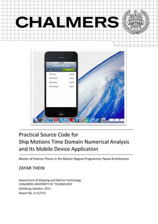
  • 33. 25 Figure 12: Mac OS X is housing the iPhone and iPad SDK. The SDK’s Xcode and the Interface Builder are used to develop CBT-M. (Photo Courtesy of Lewis [11]) As show in the figure 12, CBT-M is developed using Mac OSX and the SDK, which includes Interface Builder and Xcode. The Xcode is used to manage, write, run, and debug the CBT- M—to create the computation code and functionality. Then, Interface Builder is used to drag and drop items onto the CBT-M interface. Finally, the program is compiled to the iPhone/iPad Simulator, as shown in figure 13.The CBT-M is developed to read frequency domain output from CBT and compute the time domain for motion due to radiation forces. Because of a lack of available researcher time, CBT-M has not been implemented for plotting. The heave, roll, and pitch response values in meters and degrees are shown, along with the specified time value. The graphical user interface for CBT-M is shown in figure 13. Finally, discipline and rules for the source code development must be explained. This development work is an ongoing project. The codes must be written in a standardized way so that other researchers can easily modify, edit, or use them for future development. Thus, the name for user interface or communication and control code files will include the letters (frm) along with a given name. A support code file used for specific purposes will be named starting with the letter (c). Similarly, structure array variables will be named with the letters (struct) at the beginning. String variables will be named starting with the letter (s). The detailed discipline and rules developed in this project is listed in Appendix E. The MATLAB code can be downloaded from the thesis website as provided below: http://web.student.chalmers.se/groups/mpnav/section/thesis/timedomain/
  • 34. 26 Figure 13: Screen shot of Chalmers Big Time Mobile program user interface in the iOS simulator mode. Users can update calculation options by pressing the green command button on the right. CBT-M reads the frequency domain and required external force solutions, prepared by the source code, and computes the ship motions. 3.4. Summary The source code, developed in MATLAB, includes two major parts: the user interface and the calculation engine. The user interface can read NURBS ship models. The input data required for calculation can be entered through the user interface. Before time domain computation, the NURBS ship form is analyzed for stability information as well as hydrodynamic coefficients: added mass, damping, and stiffness coefficients. The coefficients are saved in a temporary file for later used without re-computing the NURBS form. The full strip computation is carried out only if a new NURBS form is loaded. The file is updated as soon as the first part, strip computation, is completed. At that time, strip information may be written to a file to be used in iOS. The strip information can be read both from the MATLAB-based CBT program and from the iOS-based CBT-M. The source code CBT can compute full time- domain analysis while CBT-M only computes basic motions equations in the time domain.
  • 35. 27 4. Results, Validation, and Discussion 4.1. Overview The purpose of this section is to validate the results of the Chalmers Big Time source code. The code is tested against wave loads on a well-known ITTC container model, S175. The comparison is also made with the simple box rectangular shape. 4.2. Box Ship Validation To analyze simple results such as hydrodynamic coefficients in the frequency domain, a rectangular box-shaped ship is tested first. When the model is loaded from Chalmers Big Time, CBT computes the main particulars, and hence the particulars are validated and listed in table 3. User entry data for computation are listed in table 4. Dimensionless box-ship response results for heave, roll, and pitch are compared with those of Ship Motion Control– Lewis and shown in figure 9. Most of the data used in this validation process have been borrowed from Erik Ovegård, who has previously worked on parametric rolling. Table 3: The particulars of the rectangular box shaped vessel computed by CBT Particulars Unit Model Value CBT Result Percent Error (%) LBP m 40 40 0 Beam m 8 8 0 Depth m 2 2 0 Water Plane Area m2 320 320 0 Volume m3 640 640 0 Table 4: User entry data for box ship computation Particulars Unit Model Value LCG m 20 VCG m 2 Radius of Inertia, roll m 3.2 Radius of Inertia, pitch m 10 Radius of Inertia, yaw m 10
  • 36. 28 Figure 14: Frequency response functions for the box shaped vessel at zero speed. The amplitude of the wave is 0.1 m and the angle of attack is 45 degree. Heave and pitch responses closely follow the SMC-Lewis results. However, in roll motion, the simulation predicts a higher response than SMC’s values for cases in which the wave frequency is closer to the neutral frequency. Beam sea responses are further studied; the differences between the CBT-simulated results and the SMC’s results become smaller in beam seas. The discrepancy may arise from using different roll prediction methods. The improvement in roll motion prediction will be required for future development and modification of source code. Validating the results with more reliable model test data may be necessary. 0 0.5 1 1.5 2 2.5 0 0.5 1 1.5 2 ω[rad/s] η3 [Dimensionless] 0 0.5 1 1.5 2 2.5 0 0.5 1 1.5 2 ω[rad/s] η4 [Dimensionless] 0 0.5 1 1.5 2 2.5 0 0.5 1 1.5 2 ω[rad/s] η5 [Dimensionless] CBT SMC Lewis
  • 37. 29 4.3. Validation of Adopted Methods The portion of the source code that supports the conformal mapping is tested using the data provided by Journée. [9] The plot is shown in figure 15 and demonstrates that the conformal mapping code is valid. Furthermore, Ikeda’s prediction method implemented for viscous damping is verified by comparing the results with Ikeda’s published results [6]. The plot shown in figure 16 indicates that the implemented prediction code is a correct representation of the Ikeda’s method. Figure 15: CBT Close-Fit Conformal Mapping Validation of a half cross section model. The computation achieves good mapping result for the time domain simulation. Figure 16: Results of Ikeda’s prediction method at length/breadth=6.0, breadth/depth=4.0, block coefficient =0.65, mid-ship section coefficient =0.98, roll angle=10°, bilge keel breadth/breadth=0.025 and bilge keel length/Lpp=0.2. 0 2 4 6 8 10 12 14 0 1 2 3 4 5 6 7 8 9 y (m) z(m) CBT Mapped Model Data 0.2 0.3 0.4 0.5 0.6 0.7 0.8 0.9 1 0 0.005 0.01 0.015 0.02 ωhead B44 Ikeda's method Total CBT Damping Total Eddy Component Wave Component Bilge Keel Component
  • 38. 30 4.4. Validation and Numerical Results for the S175 In this subsection, the motions of ITTC container S175 will be simulated using CBT. As per ITTC guidelines and recommendations for the numerical study, the body plan of S175 is first described in figure 16. The main particulars of the S-175 container ship are given in table 5 and 6. Figure 16: Body plan of ITTC container ship S175. IGS file of S175 was created during the project. Table 5: The particulars of container vessel S175 computed by CBT Particulars Unit Model Value CBT Result Percent Error (%) LBP m 175 175 0 Beam (amidships) m 25.4 25.4 0 Depth (amidships) m 9.5 9.5 0 Water Plane Area m2 3147 3152 0.2 Volume m3 24140 24016 0.5 Table 6: User entry data for S175 simulation Particulars Unit Model Value LCG (aft midship) m 2.34 VCG (above base line) m 9.52 Radius of Inertia, roll m 8.3 Radius of Inertia, pitch m 42.8 Block Coefficient 0.57
  • 39. 31 For S-175 model, bilge keel length and breadth are 43.75 m and 0.45 m respectively. Valid application of the Ikeda roll damping prediction method is limited to certain ships. Table 7 verifies that S175 is a valid model for using Ikeda’s prediction method. Table 7: S175 Validity test to use the Ikeda’s roll damping prediction Parameter S175 Value Requirement Pass/Fail Block Coefficient, Cb 0.57 0.5 ≤ ≤ 0.85 Pass Breadth to Draft Ratio, B/T 2.7 2.5 ≤ B/T ≤ 4.5 Pass OG to draft Ratio, OG/T -2.0 e-3 −1.5 ≤ OG/T ≤ 0.2 Pass Mid-ship section Coefficient, Cm 0.9 ≤ ≤ 0.99 N/A A regular wave model is used to validate S175 motion. Constant amplitude 1 m, angular frequency 0.598 rad/s (wave period 10.5s), and water depth 100 m are used to generate regular waves as shown in figure 17. The simulation of the S175 model includes three wave directions: head waves, four-point bow waves (45 degrees from ahead), and beam waves. Figure 17: Time histories of wave elevation at mid-ship. Amplitude 1 m and wave period 10.5 s are used in S175 validations. Wave number is 0.03650 m-1 . Wave length to ship length ratio is 0.98. Frequency dependent added mass and potential damping solutions at zero speed are shown in figures 18 and 19, respectively. They are validated against ShipX Vessel Responses (VERES) data. Coefficients not shown here are zero. 0 2 4 6 8 10 12 14 16 18 20 -1.5 -1 -0.5 0 0.5 1 1.5 t(s) ζ(m)
  • 40. 32 Figure 18: Frequency dependent added mass A11, A22, A33, A44, A55, A66, A24, A26, A35, and A46 for the S-175 container ship at zero speed. 0 0.2 0.4 0.6 0 2 4 6 x 10 6 frequency(rad/s) A11 0 0.2 0.4 0.6 1 2 3 4 x 10 7 frequency(rad/s) A22 0 0.2 0.4 0.6 2 4 6 x 10 7 frequency(rad/s) A33 0 0.2 0.4 0.6 1 2 3 4 x 10 8 frequency(rad/s) A44 0 0.2 0.4 0.6 2 4 6 8 x 10 10 frequency(rad/s) A55 0 0.2 0.4 0.6 2 4 6 8 x 10 10 frequency(rad/s) A66 0 0.2 0.4 0.6 -3 -2 -1 0 x 10 7 frequency(rad/s) A24 0 0.2 0.4 0.6 1 2 3 4 x 10 8 frequency(rad/s) A26 0 0.2 0.4 0.6 1 2 3 4 x 10 8 frequency(rad/s) A35 0 0.2 0.4 0.6 -3 -2 -1 0 x 10 9 frequency(rad/s) A46 CBT VERES
  • 41. 33 Figure 19: Potential damping B11, B22, B33, B44, B55, B66, B24, B26, B35, and B46 for the S-175 container ship at zero speed. 0 0.2 0.4 0.6 0 5 10 15 x 10 5 frequency(rad/s) B11 0 0.2 0.4 0.6 0 5 10 15 x 10 6 frequency(rad/s) B22 CBT VERES 0 0.2 0.4 0.6 0 1 2 x 10 7 frequency(rad/s) B33 0 0.2 0.4 0.6 0 2 4 x 10 7 frequency(rad/s) B44 0 0.2 0.4 0.6 0 1 2 3 x 10 10 frequency(rad/s) B55 0 0.2 0.4 0.6 0 1 2 x 10 10 frequency(rad/s) B66 0 0.2 0.4 0.6 -2 -1 0 1 x 10 6 frequency(rad/s) B24 0 0.2 0.4 0.6 0 5 10 15 x 10 7 frequency(rad/s) B26 0 0.2 0.4 0.6 0 5 10 15 x 10 7 frequency(rad/s) B35 0 0.2 0.4 0.6 -6 -4 -2 0 x 10 8 frequency(rad/s) B46
  • 42. 34 In the numerical calculation of current Chalmers Big Time Mobile, CBT-M, the linear Froude- Krylov force is used for a performance reason. In contrast, Chalmers Big Time source code fully implies the non-linear Froude-Krylov method. Response of S175 at zero speed with head on waves is shown in figure 20. The initial condition for the simulation is taken from a previous trail; heave motion 0.56 m and pitch motion 0.003 rad are used. Figure 20: Chalmers Big Time’s time domain numerical simulation results for S-175 at zero speed with zero degree head-on waves. Wave amplitude is 1m and peak frequency is 0.598 rad/s. 0 10 20 30 -2.5 -2 -1.5 -1 -0.5 0 x 10 -3 t(s) η1 (m) 0 10 20 30 -8 -6 -4 -2 0 x 10 -6 t(s) η2 (m) 0 10 20 30 -1 -0.5 0 0.5 1 t(s) η3 (m) 0 10 20 30 -1 0 1 2 3 x 10 -6 t(s) η4 (rad) 0 10 20 30 -0.015 -0.01 -0.005 0 0.005 0.01 0.015 t(s) η5 (rad) 0 10 20 30 0 0.2 0.4 0.6 0.8 1 x 10 -6 t(s) η6 (rad)
  • 43. 35 The results indicate that the ship has about 0.56m oscillating heave motion and 0.7 degree oscillating pitch motion. Very small surge, sway, roll, and yaw are negligible. They show that the heave and pitch motions follow the wave pattern as shown in figure 17. When the wave elevation is at the maximum, the heave motion reaches its peak that agrees with the theory. Since the wave length is slightly less than the ship length (98% of the ship length), 0 pitch angle occurs slightly after the wave elevation is at the maximum or minimum. Simulation agrees that there is no sway motion or rolling when a ship encounters with head on waves. However, there should be surge motion in the simulation. Further investigation is needed to validate the surge motion. The heave and pitch motion results are then validated against ShipX Vessel Responses (VERES) linear frequency domain strip solutions and shown in figure 21 and 22. Figure 21: Comparison of S-175 heave motion time histories between Chalmers Big Time and VERES programs. S-175 is at zero speed with zero degree head-on waves. Figure 22: Comparison of S-175 pitch motion time histories between Chalmers Big Time and VERES programs. S-175 is at zero speed with zero degree head-on waves 0 5 10 15 20 25 30 -1 -0.5 0 0.5 1 t(s) η3 (m) CBT VERES 0 5 10 15 20 25 30 -0.04 -0.03 -0.02 -0.01 0 0.01 0.02 0.03 0.04 t(s) η5 (rad) CBT VERES
  • 44. 36 The comparisons suggest that CBT over predicts the heave motion and captures less pitch response than the linear solutions of VERSE program. one of the possible reasons for discrepancies is that CBT cannot capture full Froude-Krylov effect from the current S-175 model used in the simulation. The model considers only the pressure points below the 9.5 m design draft, the draft used by VERSE. Thus, for 1 m amplitude wave model, the more accurate solution than the solutions in figure 21 and 22 may be achieved if 8.5 m draft is used instead. Figure 23: Simulation results for S-175 at zero forward speed with head sea 0 degree, bow sea 45 degree, and beam sea 90 degree. 0 10 20 30 -0.4 -0.2 0 0.2 0.4 t(s) η1 (m) 0 10 20 30 -1 -0.5 0 0.5 1 t(s) η2 (m) 0° 45° 90° 0 10 20 30 -2 -1 0 1 2 t(s) η3 (m) 0 10 20 30 -0.02 -0.01 0 0.01 0.02 t(s) η4 (rad) 0 10 20 30 -0.02 -0.01 0 0.01 0.02 t(s) η5 (rad) 0 10 20 30 -0.01 -0.005 0 0.005 0.01 t(s) η6 (rad)
  • 45. 37 The simulation is repeated with the starboard bow 45 degree and starboard abeam 90 degree wave directions. The comparison between the three sea states is shown in figure 23. Surge motion coming from water line Froude-Krylov forces is large enough to be seen in the 45 degree bow sea. Sway motions are found both in the bow and beam sea. The beam sea produces the largest 0.76m sway motion. The heave motion becomes stronger as the direction of wave increases. Peak heave motion of 1.1 m is computed in the beam sea. Roll motion in the bow sea is larger than in the beam Sea. The peak roll motion of 1 degree is computed in the bow sea while only 0.4 degree roll is found in the beam sea. Similar pitch motion is computed in the bow sea. The pitch motion in the beam sea is negligible. Similarly, the largest yaw motion 0.5 degree is computed in the bow sea. The comparison shows that the ship motion in six rigid body degrees of freedom are computed as expected. 4.5. Discussion For the radiation problem, the accuracy of the numerical solution is estimated by observing the added masses and damping coefficients in the frequency domain. They are also checked for irregular behavior at the high (5 radian) and low (0.001 radian) frequencies. The computed coefficients are also compared with analytical results. The coefficient results from CBT indicate that the radiation forces computed and used in the equations are accurate. The viscous forces are treated using Ikeda’s semi-empirical method. Some discrepancies in roll motion may have come from neglecting some of the components of viscous force in the approximation. Some of the data used in Ikeda’s method are not taken from S-175. They are arbitrary and may affect the accuracy of the S-175 simulation. A range of time steps is tested to achieve the computational criteria: the best solution and the shortest computation time. MATLAB has seven ODE solvers available for different numerical schemes. The Runge–Kutta fifth order one-step solver (MATLAB ODE45), the Adams- Bashforth-Moulton multistep solver (MATLAB ODE113), and the ODE solver based on the numerical, backward differentiation formulas (MATLAB ODE15s), and the delay differential equation solver (dde23) were used to compute the best time domain solution and are tested for the above criteria. This process showed that the first solver did not converge to a solution. The Adams-Bashforth-Moulton solver provided a good solution but took more computation time than the Runge–Kutta scheme. The stiff solver saved time but did not produce a solution as good as that produced by the ABM solver. Thus, for the more accurate solution, the Adams-Bashforth-Moulton solver is recommended; for faster analysis, the stiff ODE solver is recommended. However, all of the above solvers require significant additional computing time when computing the memory force, which requires inclusion of solutions from previous time steps. The DDE23 solver is thus more efficient for this project. The results may be improved by increasing the number of strip used in computations and reducing the time and frequency step sizes. At this reporting time, reliable benchmark data and experimental results are not available for the researcher and much of the validation work is not completed. It is recommended to perform additional tests before using the current version of Chalmers Big Time program.
  • 46. 38 5. Conclusions Chalmers Big Time MATLAB source codes are developed to simulate ship motions in six degrees of rigid body freedom. The simulation uses a time domain method applied to a ship travelling with a specified mean velocity in waves. It uses the impulse-response-function time domain method, in which the hydrodynamic coefficients are computed with a 2-D linear strip method in the frequency domain and converted into the time domain. MATLAB ODE solvers are compared, and the Adams-Bashforth-Moulton multistep solver is selected in the present project. Canonical forced and free motions are considered, and the equations of motion are solved simultaneously. A range of ship profiles, wave periods, and speeds are considered. The S175 container model and a box-shape hull are used to validate the source codes. Steady-state results are compared to other published results. The simulations agree with classical ship seakeeping response. The current Chalmers Big Time MATLAB time domain simulation has several limitations. First, the simulation is intended for studying the motion of ships only. Other floating structures that are not shaped like a ship hull may not be used. The ship must be free floating; forces from mooring lines and risers are not included in the computations. Since hydrodynamic coefficients are computed in the frequency domain using strip theory, the ratio between the breadth and draft of the vessel should not be larger than 6. Therefore, the simulation does not favor very wide tanker hulls. To compute viscous damping in roll motion, Ikeda’s prediction is used. The prediction limits the type of ship to be used in the simulation. Thus, motions of vessels with a buttock flow stern such as car-carriers and large passenger ships cannot be simulated in roll motion with high accuracy. Anti-roll tanks and other stabilizers are also not considered. No maneuvering simulation is available. The present study contributes to time domain practical usage by introducing a touch-screen- based mobile device application. The intensive computation requirements of the time domain simulation and the lower capacities of current mobile devices prohibit implementation of the full six degrees of freedom time domain simulation. However, an application that reads a frequency domain pre-processed file generated by MATLAB and simulates heave, roll, and pitch motions has been developed as an outcome of this project. The study also provides an open source MATLAB code for the impulse-response function time domain analysis. In the future, the linear strip method should be replaced with a nonlinear one, which may be similar to the sectional nonlinear method. The nonlinear strip method needs to be further developed to overcome its low frequency limitation as well as its requirement for slenderness. The DDE solver should be rewritten to customize time domain computation. In time, this weak nonlinear method should be completely replaced by a fully nonlinear CFD method. The computation routines in source code should be revised so that computation time may be reduced significantly. For faster analysis, the stiff ODE solver should also be considered. Development of a touch-screen-based mobile device application should take advantage of technological advances. Its user interface must be developed to the degree that ship models and plots can be displayed. Currently, running the CBT on an iOS system slows down its multitasking performance. Perhaps the standalone file exchange design should be replaced with a cloud computing solution to achieve better computing performance. The limitations
  • 47. 39 described previously should also be addressed. Simulated results from institutions should be explored, and the program should be validated intensively. The findings show that it is feasible to develop mobile device applications for a seakeeping analysis. In general, the current Chalmers Big Time MATLAB simulation and mobile application, with their underlying numerical analysis, provide a flexible tool that can be practically applied to current problems in seakeeping. They can also be extended to increasingly complex problems in naval architecture.
  • 48. 40 6. References [1] Bergdahl, Lars. 2010 Wave-induced loads and ships motions. Göteborg, Sweden: Chalmers University of Technology [2] Couser, P. 2000. Seakeeping Analysis for Preliminary Design, Formation Design Systems. UK [3] Cummins, W.E. 1962. The Impulse Response Function and Ship Motions, Symposium on Ship Theory, Institüt für Schiffbau der Universität Hamburg, Hamburg, Germany, January 1962, Schiffstechnik, 9, 101-109 [4] Faltinsen, O.M. 1990. Sea Loads on Ships and Offshore Structures. Cambridge U.P. [5] Hua, Palmquist.1995. A Description of SMS- A Computer Code for Ship Motion Calculation. Stockholm, Sweden: KTH [6] Ikeda, Y. and etc. 2009. A Simple Prediction Formula of Roll Damping of Conventional Cargo Ships on the Basis of Ikeda’s Method and Its Limitation, Proceedings of the 10th International Conference on Stability of Ships and Ocean Vehicles. [7] ITTC. 2011. Recommended Procedures and Guidelines: Verification and Validation of Linear and Weakly Nonlinear Seakeeping Computer Codes , ITTC [8] Journee J.M.J. 1993. Hydromechanic Coefficients for Calculating Time Domain Motions of Cutter Suction Dredges by Cummins Equations. Report No. 0968. Delft, Netherlands: Delft University of Technology [9] Journee J.M.J.and and Adegeest L.J.M. 2003. Theoretical Manual of “SEAWAY for windows. Report No 1370. Delft, Netherlands: Delft University of Technology. [10] Kring, David C.1994. Time Domain Ship Motions by a Three-Dimensional Rankine Panel Method. Ph.D. Thesis. Massachusetts Institute of Technology [11] Lewis, Rory. 2011. iPhone and iPad Apps for Absolute Beginners, iOS 5 Edition 2nd Edition, New York :Apress [12] Ovegård, Erik.2009. Numerical Simulation of Parametric Rolling in Waves. Master’s Thesis. Royal Institute of Technology Centre for Naval Architecture. [13] Renilson, M.R. 1982, An Investigation into the Factors Affecting the Likelihood of Broaching-to in Following Seas. Proceedings of the 2nd International Conference on Stability and Ocean Vehicles, 551-564. Tokyo, Japan: The Society of Naval Architects of Japan. [14] Shampine L.F. and S. Thompson, Solving DDEs in Matlab, manuscript. [15] Tasai, F. 1959. On the Damping Force and Added Mass of Ships Heaving and Pitching. Report No 26, Vol. VII. Fukuoka, Japan: Research Institute for Applied Mechanics, Kyushu University.
  • 49. 41 [16] Ursell, F. 1949. On the Heaving Motion of a Circular Cylinder on the Surface of a Fluid. Quarterly Journal of Mechanics and Applied Mathematics. Vol. II. [17] Wehausen, J. V. 1971. The motion of floating bodies. Ann. Rev. Fluid Mech., 3:237_268 [18] "Mobile/Tablet Top Operating System Share Trend." netmarketshare.com. Net Applications, n.d. Web. 24 Aug. 2011.
  • 50. 42 Appendix A: Supplementary Notes in Computing Restoring and Excitation Forces The present part is largely borrowed from Hua’s Description of SMS. [5] Computing Restoring and Froude-Krylov Forces The vectors and Euclidian length in restoring and Froude-Krylov forces equation can be described in figure A1. Figure A1: Illustration of Pressure and associated vectors in a segment between two consecutive points along the cross section hull The Euclidian length of the segment i is defined as = ‖ + ‖ … (A1) where is the vector to the offset point i. The position vector is expressed in two ways based on Pressure value. When the addition of two consecutive pressures at each end of the segment i is zero, the position vector is ̂ = + . ( − ) … (A2) If the addition is zero, the position vector then is half of the difference between the vectors at each end. ̂ = .( ) … (A3) Computing Diffraction Forces To compute diffraction forces, particle velocities and accelerations in the y and z directions are required. These velocities and accelerations can be derived from wave potential and shown in equation A4 and A5 respectively. = . ( .( ) ( . ) . cos( . + . + ) + sin ( ) = − . ( .( )) ( . ) . sin( . + . + ) … (A4) ̂ ̂ Ship Hull
  • 51. 43 = − . ( .( ) ( . ) . sin( . + . + ) sin ( ) = − . ( .( )) ( . ) . cos( . + . + ) … (A5) where U is the forward ship’s speed, is phase angle, and is wave angle.
  • 52. 44 Appendix B: Basic Formulae for Viscous Damping Computation The present part is largely borrowed from Ikeda’s roll prediction method. [6] Computing Frictional Component, BF The Friction damping at Fn=0 can be expressed as = . . . … (B1) where is frictional coefficient, is average radius from the axis of rolling, is wetted surface area., is roll amplitude. The frictional coefficient is = 1.328 . . . … (B2) The average radius can be computed from = ( . . )( . . ) … (B3) and wetted surface is simply = (1.75 + ) … (B4) where is roll period, is draft, is dynamic coefficient of viscosity, and OG is the distance from calm water surface to the axis of rolling (downward direction is positive in this equation.) Computing Wave Component, Bw The computed is computed as = exp ( ( ( ) ) . ) … (B5) where coefficients A1, A2, A3, and circular frequency are defined below. = … (B6) = ( + + ) … (B7) = −1.402 + 7.189 − 10.993 + 9.45 … (B8) = + + + + + + + … (B9) = / , = 1 − / , and other coefficients are given below:
  • 53. 45 = ( + )(1 − ) + 1 = −1.05584 + 12.688 − 63.70534 + 172.84571 − 274.05701 +257.68705 − 141.40915 + 44.13177 − 7.1654 − 0.0495 +0.4518 − 0.61655 = (−0.3767 + 3.39 − 10.356 + 11.588) = −0.0727 + 0.7 − 1.2818 = −17.102 + 41.495 − 33.234 + 8.8007 36.566 − 89.203 + 71.8 − 18.108 = −7686.0287 + 30131.5678 — 49048.9664 + 42480.7709 −20665.147 + 5355.2035 − 577.8827 = 61639.9103 − 241201.0598 + 392579.5937 − 340629.4699 +166348.6917 − 43358.7938 + 4714.7918 = −130677.4903 + 507996.2604 — 826728.7127 + 722677.104 −358360.7392 + 95501.4948 − 10682.8619 = −110034.6584 + 446051.22 — 724186.4643 + 599411.9264 −264294.7189 + 58039.7328 − 4774.6414 = 709672.0656 − 2803850.2395 + 4553780.5017 − 3888378.9905 +1839829.259 − 457313.6939 + 46600.823 = −822735.9289 + 3238899.7308 — 5256636.5472 + 4500543.147 −2143487.3508 + 538548.1194 − 55751.1528 = 299122.8727 − 1175773.1606 + 1907356.1357 − 1634256.8172 +780020.9393 − 196679.7143 + 20467.0904 = + + = + + = 17.945 − 166.294 + 489.799 − 493.142 = −25.507 + 236.275 − 698.683 + 701.494 = 9.077 − 84.332 + 249.983 − 250.787 = −16.872 + 156.399 − 460.689 + 463.848
  • 54. 46 = 24.015 − 222.507 + 658.027 − 660.665 = −8.56 + 78.549 − 235.827 + 236.579 = + + = + + + = + + + = −0.002222 + 0.040871 − 0.286866 + 0.599424 = 0.010185 − 0.161176 + 0.904989 − 1.641389 = −0.015422 + 0.220371 − 1.084987 + 1.834167 = −0.0628667 + 0.4989259 + 0.52735 − 10.7918672 + 16.616327 = 0.1140667 − 0.8108963 − 2.2186833 + 25.1269741 − 37.7729778 = −0.0589333 + 0.2639704 + 3.1949667 − 21.8126569 + 31.4113508 = 0.0107667 + 0.0018704 − 1.2494083 + 6.9427931 − 10.2018992 = 0.192207 − 2.787462 + 12.507855 − 14.764856 = −0.350563 + 5.222348 − 23.974852 + 29.007851 = 0.237096 − 3.535062 + 16.368376 − 20.539908 = −0.067119 + 0.966362 − 4.407535 + 5.894703 = − … (B10) This prediction and empirical formulae may be used if the requirements listed in table B-1 are met. Table B-1: Requirements for Using Wave and Eddy Components Predictions Parameter Requirement Block Coefficient, Cb 0.5 ≤ ≤ 0.85 Breadth to Draft Ratio, B/T 2.5 ≤ B/T ≤ 4.5 Circular Frequency, ≤ 1.0 VCG to draft Ratio, OG/T −1.5 ≤ OG/T ≤ 0.2 Mid-ship section Coefficient, Cm 0.9 ≤ ≤ 0.99
  • 55. 47 Computing Eddy Component, BE The eddy component can be predicted as follow: = . . … (B11) where = exp ( + . ) … (B12) and the coefficients are = (−0.0182 + 0.0155). ( − 1.8) − 79.414 + 215.695 −215.883 + 93.894 − 14.848 = (−0.2 + 1.6). (3.98 − 5.1525). − {0.9717 − 1.55 +0.723). + (0.04567 + 0.9408)} = (0.25 + 0.95). − 219.2 + 443.7 − 283.3 + 59.6 = (46.5 + 15. ). + 11.2 − 28.6 … (B13) while and are given in above wave component part. The requirements for using this prediction method are listed in table B-1. Computing Bilge Keel Roll Damping Component, BBK Similarly, the eddy component can be found as follow: = . exp( + . ) . … (B14) where = ( , ). ( ). ( + ) … (B15) and the coefficients are = (−0.3651 + 0.3907). ( − 2.83) − 2.21 + 2.632 = 0.00255 + 0.122 − 0.4794 = (−0.8913 − 0.0733 ). + (5.2857 − 0.01185 + 0.00189). = (5 + 0.3 − 0.2 + 0.00125 − 0.0425 − 1.86). = −15 + 1.2 − 0.1 − 0.0657 − 0.0586 − 1.6164 = (2.5 + 15.75)
  • 56. 48 … (B16) is ratio between width of the bilge keel and ship breadth while is ratio between length of the bilge keel and ship Lpp. This prediction and empirical formulae may be used if the requirements listed in table B-2 in addition to table B-1 requirements are met. Table B-1: Additional Requirements for Using Bilge Keel components Prediction Parameter Requirement width to Beam ratio, 0.01 ≤ ≤ 0.06 length to Lpp ratio, Lpp 0.05 ≤ Lpp ≤ 0.4
  • 57. 49 Appendix C: Determining Added Mass and Damping Coefficients of a Ship Ursell[14] and Tasai[13] Methods are used in CBT to compute hydrodynamic coefficients. They are detailed in this section. Conformal Mapping To use Ursell’s method for determining potential coefficients, the ship cross section have to be mapped conformally to a unit circle which the method is based upon. The general transformation formula between the ship cross sectional plane and plane of the unit circle is given by: + = ∑ … (C1) where the left hand side of the equation represents the plane of the ship cross section, on the left hand side is the plane of the unit circle, is the scale factor, and are conformal mapping coefficients. Therefore, the relationships between the coordinates in the two planes can be defined as = − ∑(−1) sin ((2 − 1) ) … (C2) = ∑(−1) cos ((2 − 1) ) ... (C3) where the scale factor is. = 2 ∑ … (C4) The value of Ms together with a2n-1 values represent any complex hull geometry form and thus are useful in Tasai’s theory which will be discussed later in this section. The first guess for these coefficients is done with the Lewis conformal mapping and then an iteration loop is used to achieve a correct representation of the ship cross section. N value for Lewis conformal mapping is 3 while 10 is recommended for Close-Fit Conformal mapping. First, the half breadth to draught ratio H0 and the sectional area coefficient are defined: = 2 = 1 + + 1 − + …(C5) = = 4 1 − − 3 (1 + ) − … (C6) where AS is the area of the cross section. However, there are some limitations for using this method. The boundaries for the acceptable Lewis conventional, combined bulbous and tunneled forms are given below: For H0≤1
  • 58. 50 (2 − ) < < (10 + + ) … (C7) For H0≤1 (2 − ) < < (10 + + ) … (C8) These boundaries are described in figure C-1. Figure C1: Range of H0 and of Lewis Forms [9]. If the sectional area coefficient is outside of the range, the closest value inside the range is applied. . By using the equations C5 and C6, the following quadratic equation is derived + + = 0 … (C9) where: = 3 + 4 + 1 − 4 − 1 + 1 = 2 − 6 = − 4
  • 59. 51 Then the solutions for a1 and a3 are: = … (C10) = ( + 1) … (C11) For the first guess, a2 and all the other coefficients a2n-1 are equal to zero. Then, the angles θi is estimated using the guessed conformal mapping coefficients. With the new θi, the first approximation of the contour of the hull is achieved as follow: = ∑(−1) sin ((2 − 1) ) … (C12) = ∑(−1) cos ((2 − 1) ) … (C13) Then, the deviation between the approximated contour and the real contour of the section (y0i,z0i) is given as = ( − ) + ( − ) … (C14) Thus, the sum of the squares of deviations is: = … (C15) Using the new θi,, Ms and a2n-1 are recomputed to minimized the sum of the squares of deviations. ( ) = 0 = 0 … … (C16) Then, N+ 1 equation is: (−1) [ ] cos ((2 − 2 ) = − sin((2 − 1) ) + cos ((2 − 1) ) … (C17) To achieve the exact breadth and draught coordinates, the last two line of the N+1 equation C17 is replaced by C18 and C19 the equations for the breadth at the water line and draught. (−1) [ ] = … (C18) [ ] = 2 … (C19)
  • 60. 52 The new Ms and a2n-1 are solved using equations C17, C18, and C19. Please note that MS has to be found by dividing the final solutions [MS a2n-1] by the old MS value. Once again the new angles θi are estimated. The iteration of finding θi, Ms and a2n-1 will continue until the difference between two values of E is small as given in equation C20 Journée [9] ∆ = ( + 1)(0.00005 + …(C20) Computing 2-D Potential Coefficients The 2-D potential coefficients can be computed empirically using Tasai’s theory for deep water, Keil’s theory for shallow and deep water, or Frank’s theory for deep water. CBT uses the Tasai’s theory which is based on Ursell’s potential theory for circular cylinders and N- parameter conformal mapping. This portion is largely borrowed from Journée’s SEAWAY theory manual. [9] Heaving Motion and its Coefficients In the heaving motion, as described in equation 22 and 23, the coefficients A0, B0, M0, and N0 are required to compute sectional potential coefficients a33 and b33: A brief procedure of finding A0, B0, M0, and N0 is described below. = cos(2 ) + 1 + ∑ ( cos(2 − 1) 2m − 1 + (−1) (2 − 1) (2 + 2 − 1) cos(2 + 2 − 1) ) ψ = sin(2 ) + 1 + ∑ ( sin(2 − 1) 2m − 1 + (−1) (2 − 1) (2 + 2 − 1) sin(2 + 2 − 1) ) = − cos 2 = − sin 2 | | = − sin 2 | | + ( 2 + ( − ) sin 2 ) − = − − cos 2 | | + ( 2 − ( − ) cos 2 ) − Then, the Porter series is: = Υ + ln + + ∑∞ cos ( ) = + ∞ sin ( ) = arctan ( )
  • 61. 53 = + ! Υ = 0.57722 pm amd qm are calculated as follows: ( ) ( ) = ( ( ) − ℎ( ) 2 ) ( ) ( ) ( ) = ( ( ) − ℎ( ) 2 ) ( ) where ( ) = − ( ) + ℎ( ) 2 ℎ( ) = 1 1 + ∑ 2 −1=1 (−1) =0 2 −1 sin(2 − 1) The coefficient A0 and B0 can be described as: = 2 + 2 = 2 + 2 Finally, M0 and N0 are computed as: = − 1 + ∑ 2 −1=1 (−1) (2 − 1) =0 2 −1 cos(2 − 1) − (−1) 1 + ∑ 2 −1=1 =1 (2 − 1)2 4 2 − (2 − 1)2 2 −1 + 4 (1 + ∑ 2 −1)=1 2 ( 1 + (−1) =1 (2 − 1) 2 −1 2 +2 −1 = − 1 + ∑ 2 −1=1 (−1) (2 − 1) =0 2 −1 cos(2 − 1) − (−1) 1 + ∑ 2 −1=1 =1 (2 − 1)2 4 2 − (2 − 1)2 2 −1 + 4(1 + ∑ 2 −1)=1 2 ( 1 + (−1) =1 (2 − 1) 2 −1 2 +2 −1
  • 62. 54 Roll Motion and its Coefficients In the roll motion, as described in equation 22 and 23, the coefficients P0, Q0, X0, and Y0 are required to compute the sectional potential coefficients a44 and b44: A brief procedure of finding P0, Q0, X0, and Y0 is described below. = sin((2 + 1) ) − 1 + ∑ ( sin(2 ) 2m + (−1) (2 − 1) (2 − 2 ) sin(2 + 2 ) ) ψ = −cos((2 + 1) ) + 1 + ∑ ( cos(2 ) 2m + (−1) (2 − 1) (2 − 2 ) cos(2 + 2 ) ) = ∓ − sin 2 | | = − cos 2 = ± − cos 2 ∓ 2 − ( − ) cos 2 − ± | | 2 ( 2 + 2) = − cos 2 | | + 2 + ( − ) sin 2 − − 2 ( 2 + 2) pm amd qm are calculated as follows: ( ) ( ) = ( ( ) − 2 ) ( ) ( ) ( ) = ( ( ) − 2 ) ( ) where ( ) = − ( ) + 2 and − 4 ( ( ) − 1)( cos( ) + sin( )) Thus, P0 and Q0 are = 2 sin ( ) = 2 cos ( )
  • 63. 55 Then, YR and XR are calculated: = 1 2(1 + ∑ 2 −1)=1 (−1) (2 − 1) sin (2 − 2 ) + 1 2(1 + ∑ 2 −1)=1 (−1) (2 − 1)(2 − 2 ) (2 + 1) − (2 − 2 ) − 0 8(1 + ∑ 2 −1)=1 (−1) (−2 + 2 − 2 − 1)(2 − 1) (2 − 2 ) + (−2 − 2 + 2 − 1)(2 − 1) (2 − 2 ) = 1 2(1 + ∑ 2 −1)=1 (−1) (2 − 1) sin (2 − 2 ) + 1 2(1 + ∑ 2 −1)=1 (−1) (2 − 1)(2 − 2 ) (2 + 1) − (2 − 2 ) − 0 8(1 + ∑ 2 −1)=1 (−1) (−2 + 2 − 2 − 1)(2 − 1) (2 − 2 ) + (−2 − 2 + 2 − 1)(2 − 1) (2 − 2 ) Sway Motion and its Coefficients In the sway motion, as described in equation 22 and 23, the coefficients M0, N0, P0, and Q0 are required to compute the sectional potential coefficients a22 and b22: A brief procedure of finding M0, N0, P0, and Q0 is described below. = e ( ) sin((2 + 1) ) − (−1) (2 − 1) (2 + 2 ) . ( ) sin ((2m + 2n) ) ψ = −e ( ) cos((2 + 1) ) + (−1) (2 − 1) (2 + 2 ) . ( ) cos ((2m + 2n) ) . = − − sin ( ) = − cos ( ) . = − cos( | |)| − . ( ) + . ( ) 2 + 2 0 − − ( 2 + 2) = − − sin ( | |)| + ( ) − ( ) 2 + 2 0 − − ( 2 + 2)
  • 64. 56 Then, the Porter series is: = Υ + ln + + ∑∞ cos ( ) = + ∞ sin ( ) = arctan ( ) = + ! Υ = 0.57722 pm amd qm are calculated as follows: ( ) ( ) = ( ( ) − 2 ) ( ) ( ) ( ) = ( ( ) − 2 ) ( ) where ( ) = − ( ) + 2 The coefficient A0 and B0 can be described as: − 4 ( ( ) − 1)( cos( ) + sin( )) Thus, P0 and Q0 are = − sin ( ) = − cos ( ) Finally, M0 and N0 are computed as: = − 1 ( ) {(−1) (2 − 1) =0 2 −1 sin(2 − 1) } + 4 {(−1) 2 (2 + 1) 2 +1} −1 =1 + 2 {(−1) 2 =1 { (2 − 1)(2 − 1) (2 + 2 ) − (2 − 1) 2 −1 2 −1} is obtained by replacing by and by in the above expression.
  • 65. 57 Coupling of Roll into Sway Motion and its Coefficients In the coupling of roll into sway motion, as described in equation 22 and 23, the coefficients M0, N0, P0, and Q0 are required to compute the sectional potential coefficients a24 and b24: These M0, N0, P0, and Q0 are already computed above. Determining Added Mass and Damping Coefficients of a Ship with Forward Speed in Waves As described by Hua, [5] Ship added masses and damping coefficients are calculated as: = . − = . − = = . . + . − + = = . − = − . . − . + − = . − = . . + . − + = − . . + . + = . . − . − + = . . − . − = . . + . − + …(C21) Super subscript A and subscript a refer to mid-ship cross-section. = . +
  • 66. 58 = . + = = . . − . + + = . + = − . . + . − − = . + = . . − . + + = − . . − . − = . . + . + + = . . + . + = . . + . + = . . + . + + …(C22)
  • 67. 59 Appendix D: Big Time Tutorials Starting Chalmers Big Time Chalmers Big Time CBT can be launched either in Standalone mode or directly from MATLAB. One of the easiest ways to run CBT in MATLAB environment is starting it from MATLAB’s Guide interface. • Enter the word “guide” in MATLAB Command Window. MATLAB GUIDE Quick Start Interface • MATLAB will take you to GUIDE Quick Start Interface. • Click on Open Existing GUI tab • Browse to the folder where you kept CBT source code. Browsing forChalmersBigTime.fig from MATLAB GUIDE Quick Start Interface
  • 68. 60 • Look for ChalmersBigTime.fig file. This file should be listed at the top. • Choose the file and Click on Open • MATLAB will take you to ChalmersBigTime Interface. ChalmersBigTime Interface • Click on RUN menu icon an arrow with green color ChalmersBigTime Interface run menu icon You are now in MATLAB Big Time program environment Loading a Ship Model Currently, CBT can only read (.igs) geometry files and (.cbt) Chalmers Big Time files. (.igs) can be loaded into CBT in two ways either from drop down file menu or from menu icon. • Click on the Load Model menu icon between the file open icon and file save icon. Tool Tip will show you the words “Load Model” when you place your mouse pointer above the icon.
  • 69. 61 Loading a model from an ico. • To load model using file menu, click on File, and then Load Model. • Browse to your (.igs) file and then click open. Within a couple of seconds, you will receive model information with strip profile. Receiving the model info. • You can review your model information such as LBP at the lower left condition result area. • Stability information such as GM can be found in the same area. To review the stability information, choose from the combo box above the result field. Drop down combo box to upload available results
  • 70. 62 Reviewing Model Information • Click on Nurbs in Plot Option to view Rendered model Choosing Nurbs Reviewing Nurbs plot • Click on Open Figure command button under plot option to open the model in a new window.
  • 71. 63 Reviewing a plot in new window You should also check if there is any error or message for you in the message window on the lower right hand side area. Checkingmessages Entering User Information Currently, there are four entry forms which you may want to update the default values with your data before running the simulation. First, you should update units and coordinate system. • Click on Menu Edit, and then Edit References and Units menu. You could also clik on an appropiate icon or use short cut key Ctrl+R to update the reference and unit.
  • 72. 64 Unit/Reference system entry form. Some of the models you would analyze are in different units and reference systems. Please make sure that your settings are correct before you run the time domain simulation. • Click on Edit Draft & Hydrostatic menu to update model computation. Click on Edit Computation Options to update frequency domain computation. • Click on Edit Variables menu to update all required variables in the simulation. Running Time Domain Simulation A single click on Compute Motion command button will compute complete time domain simulation. Clicking on Cancel button will force the computation to stop. When the computation is completed, the “computation successful” message will appear in the message list box. The plots are automatically plotted in the plot area on the top right hand side. • Click on an appropriate tab to view the result plot in that direction of motion
  • 73. 65 Result plots. Saving the Results and User Entry If you wish to save your work, you could do so by clicking Save or Save As from the file menu. The file will save as (.cbt) file. Use File Open menu to load the file you have saved. You could also load this file from your mobile device if your device is installed with CBT-M.
  • 74. 66 Appendix E: Programming Guide The purpose of this section is to provide architectural background of the Chalmers Big Time Source Code. Naming System Naming system is developed for the source code so that other developers could easily verify and distinguish the variables, objects, and files. The system is listed in table E-1. Table E-1: Naming System Type Leading Letter(s) in a Given Name Variable String s Double d Boolean b Array arr Structure Array struct File figure frm m-file c (for specific purpose) mod (for general purpose)