

Empfohlen
Weitere ähnliche Inhalte
Was ist angesagt?
Was ist angesagt? (20)
Andere mochten auch
Andere mochten auch (19)
Ähnlich wie Micro Controller 8051 of Speedo Meter using KEIL Code
Ähnlich wie Micro Controller 8051 of Speedo Meter using KEIL Code (20)
Micro Controller 8051 of Speedo Meter using KEIL Code
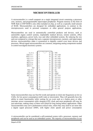
- 1. SPEEDO METER RVCE MICROCONTROLLER A microcontroller is a small computer on a single integrated circuit containing a processor core, memory, and programmable input/output peripherals. Program memory in the form of NOR flash or OTP ROM is also often included on chip, as well as a typically small amount of RAM. Microcontrollers are designed for embedded applications, in contrast to the microprocessors used in personal computers or other general purpose applications. Microcontrollers are used in automatically controlled products and devices, such as automobile engine control systems, implantable medical devices, remote controls, office machines, appliances, power tools, toys and other embedded systems. By reducing the size and cost compared to a design that uses a separate microprocessor, memory, and input/output devices, microcontrollers make it economical to digitally control even more devices and processes. Mixed signal microcontrollers are common, integrating analog components needed to control non-digital electronic systems. Some microcontrollers may use four-bit words and operate at clock rate frequencies as low as 4 kHz, for low power consumption (milli watts or microwatts). They will generally have the ability to retain functionality while waiting for an event such as a button press or other interrupt; power consumption while sleeping (CPU clock and most peripherals off) may be just nanowatts, making many of them well suited for long lasting battery applications. Other microcontrollers may serve performance-critical roles, where they may need to act more like a digital signal processor (DSP), with higher clock speeds and power consumption A microcontroller can be considered a self-contained system with a processor, memory and peripherals and can be used as an embedded system. The majority of microcontrollers in use Depart of CSE 1
- 2. SPEEDO METER RVCE today are embedded in other machinery, such as automobiles, telephones, appliances, and peripherals for computer systems. These are called embedded systems. While some embedded systems are very sophisticated, many have minimal requirements for memory and program length, with no operating system, and low software complexity. Typical input and output devices include switches, relays, solenoids, LEDs, small or custom LCD displays, radio frequency devices, and sensors for data such as temperature, humidity, light level etc. Embedded systems usually have no keyboard, screen, disks, printers, or other recognizable I/O devices of a personal computer, and may lack human interaction devices of any kind. MICROCONTROLLER FEATURES: 1. (It is similar to 8051 microcontroller i.e. having same instruction set, pin configuration, architecture). 2. It is also 8-bit microcontroller. Its cost is only Rs10 more than that of 8051. 3. It uses EPROM (erasable programmable read only memory) or FLASH memory. 4. It is multiple time programmable (MTP). The AT89C51 is a low-power, high-performance CMOS 8-bit microcomputer with 4K bytes of Flash programmable and erasable read only memory (PEROM). The device is manufactured using Atmel’s high-density nonvolatile memory technology and is compatible with the industry-standard MCS-51 instruction set and pinout. The on-chip Flash allows the program memory to be reprogrammed in-system or by a conventional nonvolatile memory programmer. By combining a versatile 8-bit CPU with Flash on a monolithic chip, the Atmel AT89C51 is a powerful microcomputer which provides a highly-flexible and cost-effective solution to many embedded control applications. The AT89C51 provides the following standard features: 4K bytes of Flash, 128 bytes of RAM, 32 I/O lines, two 16-bit timer/counters, a five vector two-level interrupt architecture, a full duplex serial port, on-chip oscillator and clock circuitry. In addition, the AT89C51 is designed with static logic for operation down to zero frequency and supports two software selectable power saving modes. The Idle Mode stops the CPU while allowing the RAM, timer/counters, serial port and interrupt system to continue functioning. The Power-down Mode saves the RAM contents but freezes the oscillator disabling all other chip functions until the next hardware reset. Depart of CSE 2
- 3. SPEEDO METER RVCE How to make a digital speedometer using microcontroller The 8051 may not be the best for this task, in that you can get types with lower power and small size (8/16 pin dip etc). That is not the only family, but it is popular with hobbyists so there are plenty of software examples on the internet. You can use this software as an example for other microprocessors too. The first decision is selecting a display that suits your microprocessor and hardware. The most basic concept is a frequency counter. Use a magnetic pickup from the wheel. This can be mounted on a spoke. You can use a fixed coil of wire or a hall effect device to detect the magnet. This can be mounted on a wheel fork, so the spoke passes close by. The coil voltage will need signal processing, like voltage limiting, an op-amp and filter, to convert to digital pulses for the Processor input. You could use an optical method instead, using LED and reflection from spokes. Count the pulses, it is best to measure period between pulses to avoid having to count for n seconds to get a meaningful result. A problem to overcome is converting this to speed, as you will have to implement maths (multiply and divide), or use a lookup table. Use a high level language like C or basic and you have maths easily. The driving of an LCD display depends on which type you have. You could look that up on the internet. For odometer, just count the impulses and totalize them, then multiply by the factor to get miles, km etc. You may want to add some sort of push button to the I/O to control the display. The power supply may be a battery, if the microprocessor uses little power, or if you use the bike power (whatever it is) it will need attention to protect everything from spikes in voltage. Good filtering before any regulator. A pic micro is the way to go. Check out www.microchip.com You should find some ideas and details in their applications section, and you can even procure a free sample or two of their controllers on their website. An easy way of counting the pulses from the wheel that will not affect tire balance might be to use a photo sensor. A simple infrared led and photo transistor, and you won't need much circuitry to condition the pulse back to the micro controller. Depending on the color and reflectivity of your tires rim, you would either attach a small section of flat black tape or a section of reflective tape to the rim in one spot. The photo sensor could be set up to either count a pulse of reflected light as a signal or the absence of a light signal as the count. Basically count the revolutions of the wheel, calculate the wheel's effective circumference, and you can compute the distance traveled per pulse. Using the micro controllers oscillator as a time base, you can calculate the number of pulses per unit of time, and using the distance traveled per pulse, figure out the speed. Depart of CSE 3
- 4. SPEEDO METER RVCE LCD interfacing with Microcontrollers tutorial ►Introduction The most commonly used Character based LCDs are based on Hitachi's HD44780 controller or other which are compatible with HD44580. In this tutorial, we will discuss about character based LCDs, their interfacing with various microcontrollers, various interfaces (8-bit/4-bit), programming, special stuff and tricks you can do with these simple looking LCDs which can give a new look to your application. ►Pin Description The most commonly used LCDs found in the market today are 1 Line, 2 Line or 4 Line LCDs which have only 1 controller and support at most of 80 charachers, whereas LCDs supporting more than 80 characters make use of 2 HD44780 controllers. Most LCDs with 1 controller has 14 Pins and LCDs with 2 controller has 16 Pins (two pins are extra in both for back-light LED connections). Pin description is shown in the table below. Figure 1: Character LCD type HD44780 Pin diagram Pin No. Name Description Pin no. 1 VSS Power supply (GND) Pin no. 2 VCC Power supply (+5V) Pin no. 3 VEE Contrast adjust 0=Instruction input Pin no. 4 RS 1 = Data input 0 = Write to LCD module Pin no. 5 R/W 1 = Read from LCD module Pin no. 6 EN Enable signal Pin no. 7 D0 Data bus line 0 (LSB) Pin no. 8 D1 Data bus line 1 Pin no. 9 D2 Data bus line 2 Pin no. 10 D3 Data bus line 3 Pin no. 11 D4 Data bus line 4 Pin no. 12 D5 Data bus line 5 Depart of CSE 4
- 5. SPEEDO METER RVCE Pin no. 13 D6 Data bus line 6 Pin no. 14 D7 Data bus line 7 (MSB) Table 1: Character LCD pins with 1 Controller Pin No. Name Description Pin no. 1 D7 Data bus line 7 (MSB) Pin no. 2 D6 Data bus line 6 Pin no. 3 D5 Data bus line 5 Pin no. 4 D4 Data bus line 4 Pin no. 5 D3 Data bus line 3 Pin no. 6 D2 Data bus line 2 Pin no. 7 D1 Data bus line 1 Pin no. 8 D0 Data bus line 0 (LSB) Pin no. 9 EN1 Enable signal for row 0 and 1 (1stcontroller) 0 = Write to LCD module Pin no. 10 R/W 1 = Read from LCD module 0 = Instruction input Pin no. 11 RS 1 = Data input Pin no. 12 VEE Contrast adjust Pin no. 13 VSS Power supply (GND) Pin no. 14 VCC Power supply (+5V) Pin no. 15 EN2 Enable signal for row 2 and 3 (2ndcontroller) Pin no. 16 NC Not Connected Table 2: Character LCD pins with 2 Controller Usually these days you will find single controller LCD modules are used more in the market. So in the tutorial we will discuss more about the single controller LCD, the operation and everything else is same for the double controller too. Lets take a look at the basic information which is there in every LCD. ►Sending Data to LCD To send data we simply need to select the data register. Everything is same as the command routine. Following are the steps: Move data to LCD port select data register select write operation send enable signal wait for LCD to process the data Keeping these steps in mind we can write LCD command routine as. Depart of CSE 5
- 6. SPEEDO METER RVCE CODE: ;Ports used are same as the previous example ;Routine to send data (single character) to LCD LCD_senddata: mov LCD_data,A ;Move the command to LCD port setb LCD_rs ;Selected data register clr LCD_rw ;We are writing setb LCD_en ;Enable H->L clr LCD_en acall LCD_busy ;Wait for LCD to process the data ret ;Return from busy routine ; Usage of the above routine ; A will carry the character to display on LCD ; e.g. we want to print A on LCD ; ; mov a,#'A' ;Ascii value of 'A' will be loaded in accumulator ; acall LCD_senddata ;Send data The equivalent C code Keil C compiler. Similar code can be written for SDCC. CODE: void LCD_senddata(unsigned char var) { LCD_data = var; //Function set: 2 Line, 8-bit, 5x7 dots LCD_rs = 1; //Selected data register LCD_rw = 0; //We are writing LCD_en = 1; //Enable H->L LCD_en = 0; LCD_busy(); //Wait for LCD to process the command } // Using the above function is really simple // we will pass the character to display as argument to function // e.g. // // LCD_senddata('A'); Depart of CSE 6
- 7. SPEEDO METER RVCE Inductive Proximity Sensor Inductive Proximity Sensors Inductive proximity sensors operate under the electrical principle of inductance. Inductance is the phenomenon where a fluctuating current, which by definition has a magnetic component, induces an electromotive force (emf) in a target object. To amplify a device’s inductance effect, a sensor manufacturer twists wire into a tight coil and runs a current through it. An inductive proximity sensor has four components; The coil, oscillator, detection circuit and output circuit. The oscillator generates a fluctuating magnetic field the shape of a doughnut around the winding of the coil that locates in the device’s sensing face. When a metal object moves into the inductive proximity sensor’s field of detection, Eddy circuits build up in the metallic object, magnetically push back, and finally reduce the Inductive sensor’s own oscillation field. The sensor’s detection circuit monitors the oscillator’s strength and triggers an output from the output circuitry when the oscillator becomes reduced to a sufficient level. Depart of CSE 7
- 8. SPEEDO METER RVCE Interfacing of 8051 micro controller with Stepper motor A Unipolar Stepper Motor is rotated by energizing the stator coils in a sequence. In unipolar stepper, the direction of current in stator coils is not required to be controlled by the driving circuit. Just applying the voltage signals across the motor coils or motor leads in a sequence is sufficient to drive the motor. A two phase unipolar stepper motor has a total of six wires/leads of which four are end wires (connected to coils) and two are common wires. The color of common wires in the stepper motor used here is Green. Each common wire is connected to two end leads thus forming two phases. The end leads corresponding to each phase have to be identified. In some cases, when the leads cannot be directly identified in the motor, the identification of endpoints and common points can be done by measuring the resistance between the leads. The leads of different phase will show open circuited condition with respect to each other. This way the leads corresponding to different phase can be separated. The resistance between any two end points of same phase will be twice the resistance between a common point and an end point. This way the common and end points of both the phases can be identified. Depart of CSE 8
- 9. SPEEDO METER RVCE To work with the unipolar stepper motor, the common points are connected to either Ground or Vcc and the end points of both the phases are usually connected through the port pins of a microcontroller. In present case the common (Green) wires are connected to Vcc. The end points receive the control signals as per the controller's output in a particular sequence to drive the motor. Depart of CSE 9
- 10. SPEEDO METER RVCE Source code MAIN.SRC #include <test_header.h> ORG 0000H LJMP MAIN STR1: DB "COUNTER =$" STR2: DB "DISTANCE=$" MAIN: LCALL INIT_RVCARD LCALL LCD_INIT MOV A,#00H MOV DPTR,#STR1 LCALL LCD_PUTS_LINE1 MOV DPTR,#STR2 LCALL LCD_PUTS_LINE2 SENSOR_RELAY11: ; this is to demonostrate the use of SENSOR and RELAY ; P1.7 -- connected to Relay input ; P3.7 -- connected to Opto Isolator input i.e sensor input ; this program reads from the sensor and controls ac device connected to relay ; continuously and it is of indefinite loop AAGAIN:JB P3.7,AAGAIN /*MOV A,#25H MOV B,#65H MUL AB MOV P0,B LCALL DELAY MOV P0,A*/ REL_ON1: MOV P0,#0FFH ADD A,#01 MOV R3,A PUSH 0E0H LCALL BINARY_TO_HEX MOV A,#8DH LCALL LCD_CWRITE MOV A,R2 LCALL LCD_DWRITE MOV A,R1 LCALL LCD_DWRITE MOV A,R0 LCALL LCD_DWRITE Depart of CSE 10
- 11. SPEEDO METER RVCE MOV A,#02 //2*3.142*r(radius)*f(rotations per second) MOV B,#01 //B contains radius 1 cm MUL AB MOV R4,A MOV A,#03// ASSUMING PI VALUE AS 3 MOV B,R3 //NO OF ROTATIONS PER SECOND MUL AB MOV B,R4 MUL AB LCALL BINARY_TO_HEX MOV A,#8DH ADD A,#40H LCALL LCD_CWRITE MOV A,R2 LCALL LCD_DWRITE MOV A,R1 LCALL LCD_DWRITE MOV A,R0 LCALL LCD_DWRITE POP 0E0H //LCALL DISP_DIST AGAIN1: JNB P3.7,AGAIN1 SJMP SENSOR_RELAY11 SJMP $ END Depart of CSE 11
- 12. SPEEDO METER RVCE STEPPER.SRC #include <test_header.h> ORG 0000H LJMP AA STR1: DB "STEPPER MOTOR$" AA: LCALL INIT_RVCARD LCALL LCD_INIT MOV DPTR,#STR1 LCALL LCD_PUTS_LINE1 STEP: MOV A,#88H MOV R0,#100 ;100 steps in the clockwise direction CONT: MOV P0,A LCALL DELAYMS LCALL DELAYMS RR A ;rotate the pattern in clockwise direction //LCALL SENSOR_RELAY11 DJNZ R0,CONT SJMP STEP //LCALL SENSOR_RELAY11*/ / SJMP $ END Depart of CSE 12