SlideShare ist ein Scribd-Unternehmen logo
1 von 18
3 – D photoelasticity
Stress Freezing
Molecular structure in an Epoxy
3 – D photoelasticity
Disc under diametric compression
3 – D photoelasticity
Effect of Machining in stress freezed
               model
3 – D photoelasticity
Model fabrication and Loading
• 3-D model of the joint comprising a ball insert
  , base ring bush base ring block are fabricated
  by using Epoxy resin (ArlditeCY-230) and
  hardener (HY-951).
• The fabricated parts are assembled and
  loaded and stress frozen.
Model fabrication and stress freezing
• A suitable force is applied using dead weight
  along the ball centre.

• After stress freezing, the slices are cut from
  the stress frozen model along the loading
  plane, where the stress is maximum.
Stress Freezing
Central Slice
Integrated Photoelasticity
Principle of optical equivalence
• The retarder introduces the retardation equivalent
  to the one introduced by 3-D model.

• The azimuth of the exit light ellipse may not be
  the same as that for for a 3-D model.the necessary
  correction is done by the rotater.

• The parameters representing the retarder and
  rotater are the experimental parameters to be
  determined in integrated photoelasticity.
Principle of optical equivalence
• The retardation is termed as characteristic
  retardation and denoted by 2∆
• The orientation of the retarder is termed as
  the primary characteristic direction denoted
  by the symbol θ.
• An idealised optical element, which simply
  rotates the azimuth of the light ellipse is
  specified by the angular rotation γ
Principle of optical equivalence
• The angle γ is termed as characteristic
  rotation.
• the summary is as follows:
• Once the retardation and rotation is known at
  the point of interest, jones matrix can be
  constructed.
• Suppose take problem in which stress
  distribution is known along the light path.
Integrated photoelasticity
• Then analytically jones matrix can be written
  for each of the planes and multiply of them.

• This gives the final jones matrix and compare
  this with the jones matrix which is written
  from experimental values and find the
  parameters related to stress distribution.
Integrated photoelasticity
• So we need to assume stress distribution field
  reasonably well with several coefficients, and
  find the necessary number of equations equal
  to coefficients.
• Hence we need multiple optical paths and
  multiple collection of charecteristic
  parameters so it becomes mathematically
  intensive.

Weitere ähnliche Inhalte

Was ist angesagt?

ESA Module 3 Part-A ME832. by Dr. Mohammed Imran
ESA Module 3 Part-A ME832. by Dr. Mohammed ImranESA Module 3 Part-A ME832. by Dr. Mohammed Imran
ESA Module 3 Part-A ME832. by Dr. Mohammed ImranMohammed Imran
 
Chapter 2 geometrical_optics_a
Chapter 2 geometrical_optics_aChapter 2 geometrical_optics_a
Chapter 2 geometrical_optics_aGabriel O'Brien
 
quarter wave plate
quarter wave plate quarter wave plate
quarter wave plate salmansmd
 
Chapter 2 geometrical_optics_b
Chapter 2 geometrical_optics_bChapter 2 geometrical_optics_b
Chapter 2 geometrical_optics_bGabriel O'Brien
 
Validation of Polarization angles Based Resonance Modes
Validation of Polarization angles Based Resonance Modes Validation of Polarization angles Based Resonance Modes
Validation of Polarization angles Based Resonance Modes IJERA Editor
 
OPTOMETRY –Part IV DIFFRACTION
OPTOMETRY –Part IV      DIFFRACTIONOPTOMETRY –Part IV      DIFFRACTION
OPTOMETRY –Part IV DIFFRACTIONBurdwan University
 
Riet ch 1 engineering physics optics main
Riet ch 1 engineering physics optics mainRiet ch 1 engineering physics optics main
Riet ch 1 engineering physics optics mainhasan ziauddin
 
BettySlamaPRE2011
BettySlamaPRE2011BettySlamaPRE2011
BettySlamaPRE2011Betty Slama
 
Phong Shading over any Polygonal Surface
Phong Shading over any Polygonal Surface Phong Shading over any Polygonal Surface
Phong Shading over any Polygonal Surface Bhuvnesh Pratap
 
Fully-Polarimetric_Phased_Array_Far_Field_Modeling_2015SECONWorkshop_JHucks
Fully-Polarimetric_Phased_Array_Far_Field_Modeling_2015SECONWorkshop_JHucksFully-Polarimetric_Phased_Array_Far_Field_Modeling_2015SECONWorkshop_JHucks
Fully-Polarimetric_Phased_Array_Far_Field_Modeling_2015SECONWorkshop_JHucksJoseph Hucks, Ph.D.
 
Synthesis of Optimized Asymmetrical Sum Patterns Using Conventional Method
Synthesis of Optimized Asymmetrical Sum Patterns Using Conventional MethodSynthesis of Optimized Asymmetrical Sum Patterns Using Conventional Method
Synthesis of Optimized Asymmetrical Sum Patterns Using Conventional MethodIOSR Journals
 
IRJET- Simulation Results of Circular Horn Antenna
IRJET- 	  Simulation Results of Circular Horn AntennaIRJET- 	  Simulation Results of Circular Horn Antenna
IRJET- Simulation Results of Circular Horn AntennaIRJET Journal
 
Fabry perot etalon
Fabry perot etalonFabry perot etalon
Fabry perot etalonsalmansmd
 

Was ist angesagt? (20)

ESA Module 3 Part-A ME832. by Dr. Mohammed Imran
ESA Module 3 Part-A ME832. by Dr. Mohammed ImranESA Module 3 Part-A ME832. by Dr. Mohammed Imran
ESA Module 3 Part-A ME832. by Dr. Mohammed Imran
 
Birefringent coatings
Birefringent coatingsBirefringent coatings
Birefringent coatings
 
Chapter 2 geometrical_optics_a
Chapter 2 geometrical_optics_aChapter 2 geometrical_optics_a
Chapter 2 geometrical_optics_a
 
quarter wave plate
quarter wave plate quarter wave plate
quarter wave plate
 
Lecture 9a 2013_
Lecture 9a 2013_Lecture 9a 2013_
Lecture 9a 2013_
 
Chapter 2 geometrical_optics_b
Chapter 2 geometrical_optics_bChapter 2 geometrical_optics_b
Chapter 2 geometrical_optics_b
 
Validation of Polarization angles Based Resonance Modes
Validation of Polarization angles Based Resonance Modes Validation of Polarization angles Based Resonance Modes
Validation of Polarization angles Based Resonance Modes
 
Matrix optics
Matrix opticsMatrix optics
Matrix optics
 
Prisms
Prisms Prisms
Prisms
 
OPTOMETRY –Part IV DIFFRACTION
OPTOMETRY –Part IV      DIFFRACTIONOPTOMETRY –Part IV      DIFFRACTION
OPTOMETRY –Part IV DIFFRACTION
 
Riet ch 1 engineering physics optics main
Riet ch 1 engineering physics optics mainRiet ch 1 engineering physics optics main
Riet ch 1 engineering physics optics main
 
Brewster's angle
Brewster's angleBrewster's angle
Brewster's angle
 
BettySlamaPRE2011
BettySlamaPRE2011BettySlamaPRE2011
BettySlamaPRE2011
 
Newtons Ring
Newtons RingNewtons Ring
Newtons Ring
 
Phong Shading over any Polygonal Surface
Phong Shading over any Polygonal Surface Phong Shading over any Polygonal Surface
Phong Shading over any Polygonal Surface
 
Fully-Polarimetric_Phased_Array_Far_Field_Modeling_2015SECONWorkshop_JHucks
Fully-Polarimetric_Phased_Array_Far_Field_Modeling_2015SECONWorkshop_JHucksFully-Polarimetric_Phased_Array_Far_Field_Modeling_2015SECONWorkshop_JHucks
Fully-Polarimetric_Phased_Array_Far_Field_Modeling_2015SECONWorkshop_JHucks
 
Synthesis of Optimized Asymmetrical Sum Patterns Using Conventional Method
Synthesis of Optimized Asymmetrical Sum Patterns Using Conventional MethodSynthesis of Optimized Asymmetrical Sum Patterns Using Conventional Method
Synthesis of Optimized Asymmetrical Sum Patterns Using Conventional Method
 
IRJET- Simulation Results of Circular Horn Antenna
IRJET- 	  Simulation Results of Circular Horn AntennaIRJET- 	  Simulation Results of Circular Horn Antenna
IRJET- Simulation Results of Circular Horn Antenna
 
How mri scan works ?
How mri scan works ?How mri scan works ?
How mri scan works ?
 
Fabry perot etalon
Fabry perot etalonFabry perot etalon
Fabry perot etalon
 

Ähnlich wie 3 d potostress

Static and Dynamic analysis of a composite leaf spring
Static and Dynamic analysis of a composite leaf springStatic and Dynamic analysis of a composite leaf spring
Static and Dynamic analysis of a composite leaf springHimanshu Arun Raut
 
L11 slope deflection method (1)
L11  slope deflection method (1)L11  slope deflection method (1)
L11 slope deflection method (1)Dr. OmPrakash
 
Chapter 4 structural analysis design.pdf
Chapter 4 structural analysis design.pdfChapter 4 structural analysis design.pdf
Chapter 4 structural analysis design.pdfEmanSaleh78
 
DTAM: Dense Tracking and Mapping in Real-Time, Robot vision Group
DTAM: Dense Tracking and Mapping in Real-Time, Robot vision GroupDTAM: Dense Tracking and Mapping in Real-Time, Robot vision Group
DTAM: Dense Tracking and Mapping in Real-Time, Robot vision GroupLihang Li
 
DESIGN OF SPRINGS-UNIT4.pptx
DESIGN OF SPRINGS-UNIT4.pptxDESIGN OF SPRINGS-UNIT4.pptx
DESIGN OF SPRINGS-UNIT4.pptxgopinathcreddy
 
VHR_preliminary-system_study_issue2
VHR_preliminary-system_study_issue2VHR_preliminary-system_study_issue2
VHR_preliminary-system_study_issue2Stefano Coltellacci
 
Shear force and bending moment
Shear force and bending momentShear force and bending moment
Shear force and bending momenttalha022
 
Auto collimator angle dekkor
Auto collimator angle dekkorAuto collimator angle dekkor
Auto collimator angle dekkorNaman Dave
 
Aitc step by-step procedure for pbd of 40-story rc building_overall (20141105)
Aitc step by-step procedure for pbd of 40-story rc building_overall (20141105)Aitc step by-step procedure for pbd of 40-story rc building_overall (20141105)
Aitc step by-step procedure for pbd of 40-story rc building_overall (20141105)Ramil Artates
 
4-Internal Loadings Developed in Structural Members.pdf
4-Internal Loadings Developed in Structural Members.pdf4-Internal Loadings Developed in Structural Members.pdf
4-Internal Loadings Developed in Structural Members.pdfYusfarijerjis
 
Experiment stress analysis (esa) important question for examination preparat...
Experiment stress analysis (esa)  important question for examination preparat...Experiment stress analysis (esa)  important question for examination preparat...
Experiment stress analysis (esa) important question for examination preparat...Mohammed Imran
 

Ähnlich wie 3 d potostress (20)

Static and Dynamic analysis of a composite leaf spring
Static and Dynamic analysis of a composite leaf springStatic and Dynamic analysis of a composite leaf spring
Static and Dynamic analysis of a composite leaf spring
 
Chapter 4: Torsion
Chapter 4: TorsionChapter 4: Torsion
Chapter 4: Torsion
 
i.pdf
i.pdfi.pdf
i.pdf
 
10.01.03.083
10.01.03.08310.01.03.083
10.01.03.083
 
10.01.03.083
10.01.03.08310.01.03.083
10.01.03.083
 
L11 slope deflection method (1)
L11  slope deflection method (1)L11  slope deflection method (1)
L11 slope deflection method (1)
 
Ace 402 lec 6 ultimate bending
Ace 402 lec 6 ultimate bending Ace 402 lec 6 ultimate bending
Ace 402 lec 6 ultimate bending
 
Chapter 4 structural analysis design.pdf
Chapter 4 structural analysis design.pdfChapter 4 structural analysis design.pdf
Chapter 4 structural analysis design.pdf
 
L10
L10L10
L10
 
DTAM: Dense Tracking and Mapping in Real-Time, Robot vision Group
DTAM: Dense Tracking and Mapping in Real-Time, Robot vision GroupDTAM: Dense Tracking and Mapping in Real-Time, Robot vision Group
DTAM: Dense Tracking and Mapping in Real-Time, Robot vision Group
 
torsion
torsiontorsion
torsion
 
MAK205_Chapter5.ppt
MAK205_Chapter5.pptMAK205_Chapter5.ppt
MAK205_Chapter5.ppt
 
DESIGN OF SPRINGS-UNIT4.pptx
DESIGN OF SPRINGS-UNIT4.pptxDESIGN OF SPRINGS-UNIT4.pptx
DESIGN OF SPRINGS-UNIT4.pptx
 
VHR_preliminary-system_study_issue2
VHR_preliminary-system_study_issue2VHR_preliminary-system_study_issue2
VHR_preliminary-system_study_issue2
 
Shear force and bending moment
Shear force and bending momentShear force and bending moment
Shear force and bending moment
 
Auto collimator angle dekkor
Auto collimator angle dekkorAuto collimator angle dekkor
Auto collimator angle dekkor
 
Aitc step by-step procedure for pbd of 40-story rc building_overall (20141105)
Aitc step by-step procedure for pbd of 40-story rc building_overall (20141105)Aitc step by-step procedure for pbd of 40-story rc building_overall (20141105)
Aitc step by-step procedure for pbd of 40-story rc building_overall (20141105)
 
4-Internal Loadings Developed in Structural Members.pdf
4-Internal Loadings Developed in Structural Members.pdf4-Internal Loadings Developed in Structural Members.pdf
4-Internal Loadings Developed in Structural Members.pdf
 
Experiment stress analysis (esa) important question for examination preparat...
Experiment stress analysis (esa)  important question for examination preparat...Experiment stress analysis (esa)  important question for examination preparat...
Experiment stress analysis (esa) important question for examination preparat...
 
1
11
1
 

3 d potostress

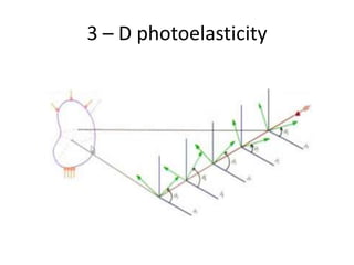
  • 1. 3 – D photoelasticity
  • 4. 3 – D photoelasticity Disc under diametric compression
  • 5.
  • 6. 3 – D photoelasticity Effect of Machining in stress freezed model
  • 7. 3 – D photoelasticity
  • 8. Model fabrication and Loading • 3-D model of the joint comprising a ball insert , base ring bush base ring block are fabricated by using Epoxy resin (ArlditeCY-230) and hardener (HY-951). • The fabricated parts are assembled and loaded and stress frozen.
  • 9. Model fabrication and stress freezing • A suitable force is applied using dead weight along the ball centre. • After stress freezing, the slices are cut from the stress frozen model along the loading plane, where the stress is maximum.
  • 13. Principle of optical equivalence • The retarder introduces the retardation equivalent to the one introduced by 3-D model. • The azimuth of the exit light ellipse may not be the same as that for for a 3-D model.the necessary correction is done by the rotater. • The parameters representing the retarder and rotater are the experimental parameters to be determined in integrated photoelasticity.
  • 14.
  • 15. Principle of optical equivalence • The retardation is termed as characteristic retardation and denoted by 2∆ • The orientation of the retarder is termed as the primary characteristic direction denoted by the symbol θ. • An idealised optical element, which simply rotates the azimuth of the light ellipse is specified by the angular rotation γ
  • 16. Principle of optical equivalence • The angle γ is termed as characteristic rotation. • the summary is as follows: • Once the retardation and rotation is known at the point of interest, jones matrix can be constructed. • Suppose take problem in which stress distribution is known along the light path.
  • 17. Integrated photoelasticity • Then analytically jones matrix can be written for each of the planes and multiply of them. • This gives the final jones matrix and compare this with the jones matrix which is written from experimental values and find the parameters related to stress distribution.
  • 18. Integrated photoelasticity • So we need to assume stress distribution field reasonably well with several coefficients, and find the necessary number of equations equal to coefficients. • Hence we need multiple optical paths and multiple collection of charecteristic parameters so it becomes mathematically intensive.