Weitere ähnliche Inhalte
Ähnlich wie Project doc (20)
Kürzlich hochgeladen (20)
Project doc
- 1. SRC 362 . Project Documentation . T1 . 2010 Assignment 2 page 1 / 5
James Coulson . Senior Lecturer . School of Architecture + Building © Deakin University 2010
ASSIGNMENT 2: PROJECT DOCUMENTATION Parapet Roof House
Introduction
This project promotes engagement with the complexity of project specific documentation. It requires
the application of general construction knowledge to a given context and, through group research and
decision-making, emulates aspects of a professional consultancy process.
The project adopts a small building design delineated with basic graphic information (schematic
design) and additional text information (outline specification) which directs the subsequent information
search and generates a different detailed solution for each group.
The main variables are the prescribed primary construction systems (nominated in the outline
specifications) and the site conditions (nominated contour and geo-technology). The profound
effect of these influences on project specific construction and detail refinement (design development)
is a major element of the unit learning.
Once the group decision-making is 'complete', students share the information and produce their own
documentation for assessment. This stage highlights the fact that decision-making is never finished
and the precise nature of the final documentation process introduces new 'gaps' in the information that
preliminary detailing missed.
The ultimate emphasis of the project is for comprehension of the three-dimensional nature of building
construction, effective representation of the construction with orthographic projection and 3D
modelling techniques and appropriate communication (information retrieval) through the application of
referencing, symbols, object delineation, dimensions, labels and notation.
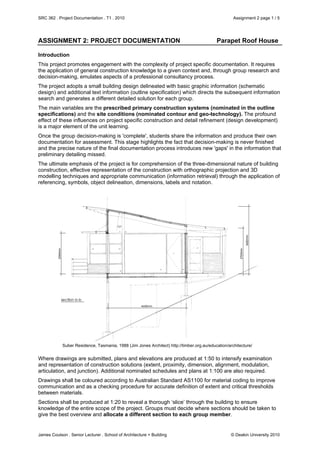
Suber Residence, Tasmania, 1988 (Jim Jones Architect) http://timber.org.au/education/architecture/
Where drawings are submitted, plans and elevations are produced at 1:50 to intensify examination
and representation of construction solutions (extent, proximity, dimension, alignment, modulation,
articulation, and junction). Additional nominated schedules and plans at 1:100 are also required.
Drawings shall be coloured according to Australian Standard AS1100 for material coding to improve
communication and as a checking procedure for accurate definition of extent and critical thresholds
between materials.
Sections shall be produced at 1:20 to reveal a thorough ‘slice’ through the building to ensure
knowledge of the entire scope of the project. Groups must decide where sections should be taken to
give the best overview and allocate a different section to each group member.
- 2. SRC 362 . Project Documentation . T1 . 2010 Assignment 2 page 2 / 5
James Coulson . Senior Lecturer . School of Architecture + Building © Deakin University 2010
Details, typically referenced from the section, shall be produced at a suitable scale (1:10, 1:5, 1:2) to
allow closer scrutiny of enclosure and connection at important junctions. Individual group members
shall take responsibility for a different element; such footing details, roof details, window details or
stair details.
Project Requirements
1. Each project group shall use the same building ‘design’ but with a different principal construction
system and nominated site condition, as confirmed for the group.
2. Working drawings shall comprise floor plans and elevations at 1:50 and a section at 1:20 that
effectively illustrates the general construction. Show the site plan at the ground floor level and
indicate cut and fill within the site boundary. All students shall include a 1:100 roof plan indicating
internal drainage to a parapet roof. Post and beam shall include 1:100 framing plans (ground and
first floors and roof). Tilt panel shall include a 1:100 panel elevation schedule and a 1:100 roof
framing plan. Earth and masonry shall include 1:100 slab plan (ground floor) and 1:100 framing
plans (first floor and roof). Include approx. 4 x 1:5 scale details per student that preferably
complement the section. Maximum of 4 x A1 sheets per student.
3D model submissions shall provide suitable content of corresponding scope.
3. Graphical information shall be appropriately coloured for construction materials. Use the NSW
Government Dept. of Technical & Further Education "Standard Drawing Symbols, Abbreviations,
Graphical Representation" and AS 1100: Drawing Practice as references.
4. Preliminary work shall be developed in groups but final submissions on A1 sheets in landscape
format or 3D models must be individual. Each student in a group shall select a different 1:20
section location.
5. Schematic design information and an outline specification for each construction type provide the
preliminary information to commence documentation. The initial design should only be changed
to suit the construction technique through consensus within the group and without significant
alteration to the floor area or to the amenity of the current design.
6. Group information in the form of developed outline specifications, preliminary plans, elevations
and a preliminary 1:20 section and critical details from each student, should be completed
and assembled in a common copy (project file) accessible to each group member. This will
include regulatory constraints, product literature, sketch layouts and details, all clearly labelled
and indexed.
7. Submit a review folder of this group information to James Coulson by 3pm Thursday, 29th April.
This review folder must remain available to all group members for the project duration.
8. The group may work together beyond this date if there is consensus within the group.
9. You are not permitted to access the project folders of other groups.
10. Final submission of individual projects is 3pm, Thursday, 20th May. Submit a 4 x colour A1
hardcopy set for marking and feedback purposes. Also submit 4 x colour A1 PDF files (printed to
PDF file or scanned) on DSO in the Assignment 3 folder. Files shall be clearly identified as
‘Surname, Given Name 362.10.A2.01’ (01 indicating sheet number 1, 02 = sheet 2, etc).
Assessment
This project is 50% of the total assessment value for SRC 362. The group folder submission is 25%
and the individual submission is 75% of the project value.
Project Site Conditions
AS 2870
Residential
Slabs & Footings
(Australian
Standard)
Group A: 7.5 degree fall to east, moderately reactive soil (M)
Group B: 7.5 degree fall to north, moderately reactive soil (M)
Group C: 5 degree fall to south-west, slightly reactive soil (S)
Group D: 7.5 degree fall to west, moderately reactive soil (M)
Group E: 7.5 degree fall to south, moderately reactive soil (M)
Group F: 5 degree fall to north-east, slightly reactive soil (S)
- 3. SRC 362 . Project Documentation . T1 . 2010 Assignment 2 page 3 / 5
James Coulson . Senior Lecturer . School of Architecture + Building © Deakin University 2010
The site is 25 metres deep x 20 metres wide. The group must decide on the street frontage and
orientation of the building to suit site boundaries, setbacks, site falls and building egress. Vehicle
access is required to the lower level – a carport may be added at the discretion of the group.
Outline Specification: Timber Post + Beam
Footings: Concrete pad footings with steel brackets to support posts
Posts: Species and sizes to be nominated
Beams & Joists: Species and sizes to be nominated
Bracing System Infill shear walls or diagonal cross bracing
Flooring: Australian hardwood tongue & groove strip flooring. Clear finish
except for tiles in wet areas. Provide insulation & lining as required.
Infill Walls: Timber studs; species, size & spacing to be determined
External Wall Lining: Timber tongue & groove boards; direction, cover, thickness, profile &
species to be determined
Internal Lining: Plasterboard; thickness to be determined
Windows: Timber with double hung operable sashes; species to be determined
Stair: Australian hardwood with closed risers; species & sizes to be
determined
Roof Framing: Conventional timber framing; species & sizes to be determined
Parapet Roofing: Profiled sheet zincalum steel with zincalum accessories
Service Reticulation: Electrical wiring, plumbing, heater flue, TV antenna
Outline Specification: Steel Post & Beam
Footings: Concrete pad footings with steel base plates to support posts
Posts: Hot rolled steel sections; sizes to be nominated
Beams & Joists: Hot & cold rolled steel sections; sizes to be nominated
Bracing System Infill shear walls or diagonal cross bracing
Flooring: Sheet flooring. Ground floor - tiles, first floor - carpet & tiles. Provide
insulation & lining as required.
Intermediate Walls: Steel studs; size & spacing to be determined
External Wall Lining: Corrugated sheet zincalum steel with zincalum accessories
Internal Lining: Plasterboard; thickness to be determined
Windows: Metal with awning operable sashes; profiles to be determined
Stair: Steel stringers with steel treads & risers; sections & sizes to be
determined
Roof Framing: Steel framing; sections & sizes to be determined
Parapet Roofing: Profiled sheet zincalum steel with zincalum accessories
Service Reticulation: Electrical wiring, plumbing, heater flue, TV antenna
Outline Specification: Precast Reinforced Concrete (tilt panel)
Footings: Reinforced concrete raft slab
Flooring: Ground floor; tiles. First floor; tiles
First Floor: Reinforced suspended concrete slab
Load-bearing Walls 150mm reinforced concrete tilt panels
Bracing System Shear walls
Non L/B Walls: To be determined
External Wall Finish: To be determined
Internal Lining: To be determined
Windows: Aluminium with awning sashes; profiles to be determined
Stair: Concrete treads; sections & sizes to be determined
- 4. SRC 362 . Project Documentation . T1 . 2010 Assignment 2 page 4 / 5
James Coulson . Senior Lecturer . School of Architecture + Building © Deakin University 2010
Parapet Roofing: Profiled sheet zincalum steel with zincalum accessories
Service Reticulation: Electrical wiring, plumbing, heater flue, TV antenna
Outline Specification: Rammed Earth
Footings: Reinforced concrete strip footings
Flooring: Ground floor; earth. First floor; plywood
First Floor: Timber beams and joists
Load-bearing Walls 300mm wide rammed earth
Bracing System Shear walls
Non L/B Walls: To be determined
External Wall Finish: Dung render
Internal Lining: To be determined
Windows: Timber with horizontal sliding sashes; species to be determined
Stair: Timber treads; sections & sizes to be determined
Parapet Roofing: Profiled sheet zincalum steel with zincalum accessories
Service Reticulation: Electrical wiring, plumbing, heater flue, TV antenna
Outline Specification: Load Bearing Masonry
Footings: Reinforced concrete strip footings
Flooring: Ground floor; masonry. First floor; masonry
First Floor: Steel beams and joists
Load-bearing Walls 230 solid and 270 cavity brickwork
Bracing System Masonry shear walls
Non L/B Walls: To be determined
External Wall Finish: Fairface; course rod and jointing to be nominated
Internal Lining: To be determined
Windows: Timber with awning sashes; species to be determined
Stair: Masonry treads
Parapet Roofing: Profiled sheet zincalum steel with zincalum accessories
Service Reticulation: Electrical wiring, plumbing, heater flue, TV antenna
Outline Specification: Straw Bale
Footings: Reinforced concrete raft slab
Flooring: Ground floor; tiles. First floor; tiles
First Floor: Timber beams and joists
Load-bearing Walls Straw bale?
Bracing System Straw bale shear walls or braced post & beam frame
Non L/B Walls: Straw bale?
External Wall Finish: Rendered straw bale
Internal Lining: To be determined
Windows: Timber with awning sashes; species to be determined
Stair: Timber treads; sections & sizes to be determined
Parapet Roofing: Profiled sheet zincalum steel with zincalum accessories
Service Reticulation: Electrical wiring, plumbing, heater flue, TV antenna
Group Formation and Evaluation for Assignment 2 and Assignment 3
All students are responsible for commencing and maintaining group contact and establishing a
program for group meetings, records and project development.
- 5. SRC 362 . Project Documentation . T1 . 2010 Assignment 2 page 5 / 5
James Coulson . Senior Lecturer . School of Architecture + Building © Deakin University 2010
This project attempts to emulate office practice by adopting project teams as a working method.
However, in consideration of equitable assessment, no 'job captains' or 'project architects' are
appointed. Group dynamics form part of any team-based activity and consequently influence
outcomes. Students are expected to participate in the group activity as part of the unit learning.
Each student is responsible for progress of the project. All group members can evaluate this process
at the end of the project. Criteria for the confidential group evaluation are as follows:
Attendance at meetings.
Participation in group discussion and group folder.
Completion and contribution of initial investigation tasks.
Contribution of suitable graphic and textual information.
Coordination of the final project presentation.
Performance against each of the criteria should be rated as poor, good or very good. In addition, for
each group member (including yourself) give an overall evaluation as a mark out of 10. Make up a
group spreadsheet or table to coordinate a uniform group presentation of this evaluation.
Submit group evaluations individually at the conclusion of Assignment 3 via email to James Coulson
by 5pm Friday 4
th
June. Non-submission will indicate satisfaction with the performance of all group
members.