SlideShare ist ein Scribd-Unternehmen logo
1 von 32
Downloaden Sie, um offline zu lesen
6/19/2015 1Hareesha N G, Dept of Aero Engg, DSCE, Blore
Unit 1: Static Force Analysis
• Static force analysis
– Introduction
– Static equilibrium
– Equilibrium of two and three force members
– Members with two forces and torque
– Free body diagrams
– principle of virtual work
• Static force analysis of
– four bar mechanism
– slider-crank mechanism with and without friction.
6/19/2015 Hareesha N G, Dept of Aero Engg, DSCE, Blore 2
STATIC EQUILIBRIUM
• A body is in static equilibrium if it remains in its state of rest or
motion.
• If the body is at rest, it tends to remain at rest and if in motion, it
tends to keep the motion.
• In static equilibrium,
– the vector sum of all the forces acting on the body is zero and
– the vector sum of all the moments about any arbitrary point is zero.
• Mathematically,
• In a planer system, forces can be described by two-dimensional
vectors and therefore,
6/19/2015 Hareesha N G, Dept of Aero Engg, DSCE, Blore 3
EQUILIBRIUM OF TWO AND THREE-FORCE MEMBERS
• A member under the action of two forces will be in
equilibrium if
– the forces are of the same magnitude,
– the forces act along the same line, and
– the forces are in opposite directions.
• Figure shows such a member.
• A member under the action of three forces will be in
equilibrium if
– the resultant of the forces is zero, and
– the lines of action of the forces intersect at a point (known as
point of concurrency).
6/19/2015 Hareesha N G, Dept of Aero Engg, DSCE, Blore 4
EQUILIBRIUM OF TWO AND THREE-FORCE MEMBERS (Contd….)
• Figure (a) shows a member acted upon by three forces F1, F2 and F3
and is in equilibrium as the lines of action of forces intersect at one
point O and the resultant is zero.
• This is verified by adding the forces vectorially [Fig.(b)].
• As the head of the last vector F3 meets the tail of the first vector F1,
the resultant is zero.
• Figure (d) shows a case where the magnitudes and directions of the
forces are the same as before, but the lines of action of the forces do
not intersect at one point.
• Thus, the member is not in equilibrium.
6/19/2015 Hareesha N G, Dept of Aero Engg, DSCE, Blore 5
• Consider a member in equilibrium in which force F1 is completely
known, F2 known in direction only and F3 completely unknown.
• The point of applications of F1 , F2 and F3 are A, B and C respectively.
• To solve such a problem, first find the point of concurrency O from the
two forces with known directions, i.e. from F1, and F2.
• Joining O with C gives the line of action of the third force F3.
• To know the magnitudes of the forces F2 and F3, take a vector of proper
magnitude and direction to represent the force F1.
• From its two ends, draw lines parallel to lines of action of the forces F2
and F3 forming a force triangle [Fig.].
• Mark arrowheads on F2 and F3 so that F1 , F2 and F3 are in the same
order.
6/19/2015 Hareesha N G, Dept of Aero Engg, DSCE, Blore 6
MEMBER WITH TWO FORCES AND A TORQUE
• A member under the action of two forces and an applied torque will
be in equilibrium if
– the forces are equal in magnitude, parallel in direction and opposite in sense
and
– the forces form a couple which is equal and opposite to the applied torque.
• Figure shows a member acted upon by two equal forces F1, and F2
and an applied torque T for equilibrium,
where T, F1 and F2 are the magnitudes of T, F1 and F2 respectively.
• T is clockwise whereas the couple formed by F1, and F2 is counter-
clockwise.
6/19/2015 Hareesha N G, Dept of Aero Engg, DSCE, Blore 7
FORCE CONVENTION
• The force exerted by member i on member j is represented
by Fij
6/19/2015 Hareesha N G, Dept of Aero Engg, DSCE, Blore 8
FREE BODY DIAGRAMS
• A free body diagram is a sketch or diagram of a part isolated from the
mechanism in order to determine the nature of forces acting on it.
• Figure (a) shows a four-link mechanism.
• The free-body diagrams of its members 2, 3 and 4 are shown in Figs.
(b), (c) and (d) respectively.
• Various forces acting on each member are also shown.
• As the mechanism is in static equilibrium, each of its members must
be in equilibrium individually.
6/19/2015 Hareesha N G, Dept of Aero Engg, DSCE, Blore 9
• Member 4 is acted upon by three forces F, F34 and F14.
• Member 3 is acted upon by two forces F23 and F43
• Member 2 is acted upon by two forces F32 and F12 and a torque T.
• Initially, the direction and the sense of some of the forces may not be
known.
• Link 3 is a two-force member and for its equilibrium F23 and F43 must
act along BC.
• Thus, F34 being equal and opposite to F43 also acts along BC.
6/19/2015 Hareesha N G, Dept of Aero Engg, DSCE, Blore 10
• Assume that the force F on member 4 is known completely.
• To know the other two forces acting on this member completely, the
direction of one more force must be known.
• For member 4 to be in equilibrium, F14 passes through the intersection
of F and F34 .
• By drawing a force triangle (F is completely known), magnitudes of
F14 and F34 can be known [Fig.(e)].
Now F34 = F43 = F23 = F32
• Member 2 will be in equilibrium if F12 is equal, parallel and opposite
to F32 and
6/19/2015 Hareesha N G, Dept of Aero Engg, DSCE, Blore 11
A four-link mechanism with the following dimensions is acted upon by
a force 80N at angle 1500 on link DC [Fig.(a)): AD = 50 mm, AB = 40 mm,
BC = 100 mm, DC = 75 mm, DE = 35 mm. Determine the input torque T
on the link AB for the static equilibrium of the mechanism for the given
configuration.
6/19/2015 Hareesha N G, Dept of Aero Engg, DSCE, Blore 12
As the mechanism is in static equilibrium, each of its
members must also be in equilibrium individually.
Member 4 is acted upon by three forces F F34 and F14.
Member 3 is acted upon by two forces F23 and F43
Member 2 is acted upon by two forces F32 and F12 and
a torque T.
Initially, the direction and the sense of some of the
forces are not known.
Force F on member 4 is known completely. To know the other two forces acting
on this member completely, the direction of one more force must be known. To
know that, link 3 will have to be considered first which is a two-force member.
• As link 3 is a two-force member [Fig.(b)], for its equilibrium, F23 and
F43 must act along BC (at this stage, the sense of direction of forces F23
and F43 is not known). Thus, the line of action of F34 is also along BC.
• As force F34 acts through point C on link 4, draw a line parallel to BC
through C by taking a free body of link 4 to represent the same. Now,
as link 4 is three force member, the third force F14 passes through the
intersection of F and F34 [Fig (c)].
• By drawing a force triangle (F is completely known), magnitudes of
F14 and F34 are known [Fig(d)].
6/19/2015 Hareesha N G, Dept of Aero Engg, DSCE, Blore 13
From force triangle, F34 = 47.8 N
• Now, F34 = -F43 =F23 = -F32
• Member 2 will be in equilibrium [Fig. (e)] if F12 is equal, parallel and
opposite to F32 and
T=-F32 x h = 47.8 x 39.3 = -1878.54 N.mm The input torque has to be
equal and opposite to this couple i.e. T= 1878.5 N/mm (clockwise)
h=Perpendicular distance between two equal and opposite forces.
6/19/2015 Hareesha N G, Dept of Aero Engg, DSCE, Blore 14
Figure shows a slider crank mechanism in which the resultant gas pressure 8x10⁴ N/m2
acts on the piston of cross sectional area 0.1m2 The system is kept in equilibrium as a
result of the couple applied to the crank 2, through the shaft at O2. Determine forces
acting on all the links (including the pins) and the couple on 2. OA=100mm, AB=450mm.
6/19/2015
Hareesha N G, Dept of Aero Engg, DSCE,
Blore
15
6/19/2015
Hareesha N G, Dept of Aero Engg, DSCE,
Blore
16
Force triangle for the forces acting on(4)is drawn to some suitable scale.
Magnitude and direction of P known and lines of action of F34 & F14
known.
Measure the lengths of vectors and multiply by the scale factor to get the magnitudes
of F14 & F34.
Directions are also fixed.
Since link 3 is acted upon by only two forces, F43 and F23
are collinear, equal in magnitude and opposite in direction
i.e., F43 = -F23 =8.8xl03 N
Also, F23 = - F32 (equal in magnitude and opposite in
direction).
6/19/2015
Hareesha N G, Dept of Aero Engg, DSCE,
Blore
17
Link 2 is acted upon by 2 forces and a torque, for equilibrium
the two forces must be equal, parallel and opposite and their
sense must be opposite to T2.
There fore,
F32 = -F12 =8.8xl03 N
F32 & F12 form a counter clock wise couple of magnitude,
F23 * h = F12 *h
=(8.8xl03)x0.125 = 1100 Nm.
To keep 2 in equilibrium, T: should act clockwise and
magnitude is 1100 Nm.
Note: h is measured perpendicular to F32 &F12
6/19/2015 Hareesha N G, Dept of Aero Engg, DSCE, Blore 18
For the static equilibrium of the quick return mechanism shown in Fig (a), determine the input
torque T2: to be applied on link AB Tor a force of 300N on the slider D. The dimensions of the
various links arc OA=400mm, AB=200mm, OC=800mm. CD=300mm
6/19/2015 Hareesha N G, Dept of Aero Engg, DSCE, Blore 19
• For the mechanism shown in Fig., determine the torque on the link
AB for the static equilibrium of the mechanism.
6/19/2015 Hareesha N G, Dept of Aero Engg, DSCE, Blore 20
• Answers from Composite Graphical Solution
6/19/2015 Hareesha N G, Dept of Aero Engg, DSCE, Blore 21
Graphical Solution by Superposition method
6/19/2015 Hareesha N G, Dept of Aero Engg, DSCE, Blore 22
Graphical Solution by Superposition method
6/19/2015 Hareesha N G, Dept of Aero Engg, DSCE, Blore 23
In a four-link mechanism shown in Fig., torque T3 and T4 have
magnitudes of 30N.m and2 ON. m respectively. The link lengths are AD
= 800 mm, AB = 300 mm, BC = 700 mm and CD = 400 mm. For the static
equilibrium of the mechanism, determine the required input torque T2
6/19/2015 Hareesha N G, Dept of Aero Engg, DSCE, Blore 24
In a four-link mechanism shown in Fig., torque T3 and T4 have
magnitudes of 30N.m and2 ON. m respectively. The link lengths are AD
= 800 mm, AB = 300 mm, BC = 700 mm and CD = 400 mm. For the static
equilibrium of the mechanism, determine the required input torque T2
6/19/2015 Hareesha N G, Dept of Aero Engg, DSCE, Blore 25
6/19/2015 Hareesha N G, Dept of Aero Engg, DSCE, Blore 26
Neglecting torque T3
6/19/2015 Hareesha N G, Dept of Aero Engg, DSCE, Blore 27
Neglecting torque T4
PRINCIPLE OF VIRTUAL WORK
• The principle of virtual (imaginary) work can be stated
as the work done during a virtual displacement from the
equilibrium is equal to zero.
• Virtual displacement may be defined as an imaginary
infinitesimal displacement of the system.
• By applying this principle, an entire mechanism is
examined as a whole and there is no need of dividing it
into free bodies.
6/19/2015 Hareesha N G, Dept of Aero Engg, DSCE, Blore 28
• Consider a slider-crank mechanism shown in Fig.
• It is acted upon by the external piston force F, the external
crankshaft torque T and the force at the bearings.
• As the crank rotates through a small angular displacement
δθ, the corresponding displacement of the piston is δx, the
various forces acting on the system are
– Bearing reaction at O (performs no work)
– Force of cylinder on piston, perpendicular to piston
displacement (produces no work)
– Bearing forces at A and B, being equal and opposite (AB is a
two-force member), no work is done
– Work done by torque T= T δθ
– Work done by force F = F δx
• Work done is positive if a force acts in the direction of the
displacement and negative if it acts in the opposite
direction.
6/19/2015 Hareesha N G, Dept of Aero Engg, DSCE, Blore 29
The negative sign indicates that for equilibrium, T must be applied in
the opposite direction to the angular displacement.
6/19/2015 Hareesha N G, Dept of Aero Engg, DSCE, Blore 30
6/19/2015 Hareesha N G, Dept of Aero Engg, DSCE, Blore 31
6/19/2015 Hareesha N G, Dept of Aero Engg, DSCE, Blore 32

Weitere ähnliche Inhalte

Was ist angesagt?

brakes and dynamometer
brakes and dynamometerbrakes and dynamometer
brakes and dynamometerGulfaraz alam
 
Spur gear and design of spur gear
Spur gear and design of spur gearSpur gear and design of spur gear
Spur gear and design of spur gearYash Shah
 
Theory of machine
Theory of machine Theory of machine
Theory of machine ahirehemant
 
Velocity & acceleration diagrams
Velocity & acceleration diagramsVelocity & acceleration diagrams
Velocity & acceleration diagramssherin_ginige
 
Gear and Gear trains
Gear and Gear trainsGear and Gear trains
Gear and Gear trainsMANJUNATH N
 
Module 1 introduction to kinematics of machinery
Module 1 introduction to kinematics of machineryModule 1 introduction to kinematics of machinery
Module 1 introduction to kinematics of machinerytaruian
 
Module 2 instantenous center method
Module 2 instantenous center methodModule 2 instantenous center method
Module 2 instantenous center methodtaruian
 
ME6503 - DESIGN OF MACHINE ELEMENTS UNIT - V NOTES
ME6503 - DESIGN OF MACHINE ELEMENTS UNIT - V NOTESME6503 - DESIGN OF MACHINE ELEMENTS UNIT - V NOTES
ME6503 - DESIGN OF MACHINE ELEMENTS UNIT - V NOTESASHOK KUMAR RAJENDRAN
 
Kinematic diagrams & degrees of freedom
Kinematic diagrams & degrees of freedomKinematic diagrams & degrees of freedom
Kinematic diagrams & degrees of freedomVISHNU VISWANATH
 
1.6 interference in gears
1.6 interference in gears1.6 interference in gears
1.6 interference in gearsKiran Wakchaure
 
Synthesis of Mechanisms
Synthesis of MechanismsSynthesis of Mechanisms
Synthesis of MechanismsYashh Pandya
 
Kinemetic chains, Pairs, Joints, Four bar Mechanisms (KOM)
Kinemetic chains, Pairs, Joints, Four bar Mechanisms (KOM)Kinemetic chains, Pairs, Joints, Four bar Mechanisms (KOM)
Kinemetic chains, Pairs, Joints, Four bar Mechanisms (KOM)University of Windsor
 

Was ist angesagt? (20)

brakes and dynamometer
brakes and dynamometerbrakes and dynamometer
brakes and dynamometer
 
Mechanisms
MechanismsMechanisms
Mechanisms
 
Spur gear and design of spur gear
Spur gear and design of spur gearSpur gear and design of spur gear
Spur gear and design of spur gear
 
kinematic synthesis
kinematic synthesiskinematic synthesis
kinematic synthesis
 
Theory of machine
Theory of machine Theory of machine
Theory of machine
 
Gear trains
Gear trainsGear trains
Gear trains
 
Gyroscope
GyroscopeGyroscope
Gyroscope
 
DYNAMICS OF MACHINES UNIT-1 BY Mr.P.RAMACHANDRAN/AP/MECH/KIT/CBE
DYNAMICS OF MACHINES UNIT-1 BY Mr.P.RAMACHANDRAN/AP/MECH/KIT/CBEDYNAMICS OF MACHINES UNIT-1 BY Mr.P.RAMACHANDRAN/AP/MECH/KIT/CBE
DYNAMICS OF MACHINES UNIT-1 BY Mr.P.RAMACHANDRAN/AP/MECH/KIT/CBE
 
Velocity & acceleration diagrams
Velocity & acceleration diagramsVelocity & acceleration diagrams
Velocity & acceleration diagrams
 
Gear and Gear trains
Gear and Gear trainsGear and Gear trains
Gear and Gear trains
 
Balancing of reciprocating masses
Balancing of reciprocating masses Balancing of reciprocating masses
Balancing of reciprocating masses
 
Flywheel.ppt
Flywheel.pptFlywheel.ppt
Flywheel.ppt
 
Module 1 introduction to kinematics of machinery
Module 1 introduction to kinematics of machineryModule 1 introduction to kinematics of machinery
Module 1 introduction to kinematics of machinery
 
Module 2 instantenous center method
Module 2 instantenous center methodModule 2 instantenous center method
Module 2 instantenous center method
 
ME6503 - DESIGN OF MACHINE ELEMENTS UNIT - V NOTES
ME6503 - DESIGN OF MACHINE ELEMENTS UNIT - V NOTESME6503 - DESIGN OF MACHINE ELEMENTS UNIT - V NOTES
ME6503 - DESIGN OF MACHINE ELEMENTS UNIT - V NOTES
 
Kinematic diagrams & degrees of freedom
Kinematic diagrams & degrees of freedomKinematic diagrams & degrees of freedom
Kinematic diagrams & degrees of freedom
 
Dynamics of Machinery Unit IV
Dynamics of Machinery Unit IVDynamics of Machinery Unit IV
Dynamics of Machinery Unit IV
 
1.6 interference in gears
1.6 interference in gears1.6 interference in gears
1.6 interference in gears
 
Synthesis of Mechanisms
Synthesis of MechanismsSynthesis of Mechanisms
Synthesis of Mechanisms
 
Kinemetic chains, Pairs, Joints, Four bar Mechanisms (KOM)
Kinemetic chains, Pairs, Joints, Four bar Mechanisms (KOM)Kinemetic chains, Pairs, Joints, Four bar Mechanisms (KOM)
Kinemetic chains, Pairs, Joints, Four bar Mechanisms (KOM)
 

Andere mochten auch (8)

Speed Governers
Speed GovernersSpeed Governers
Speed Governers
 
Balancing of reciprocating masses
Balancing of reciprocating massesBalancing of reciprocating masses
Balancing of reciprocating masses
 
Friction and belt drives
Friction and belt drivesFriction and belt drives
Friction and belt drives
 
Energy Conversion Engineering Laboratory Manual
Energy Conversion Engineering Laboratory ManualEnergy Conversion Engineering Laboratory Manual
Energy Conversion Engineering Laboratory Manual
 
Design and Drawing of CAM profiles
Design and Drawing of CAM profilesDesign and Drawing of CAM profiles
Design and Drawing of CAM profiles
 
Spur gears
Spur gearsSpur gears
Spur gears
 
Planar Mechanisms
Planar MechanismsPlanar Mechanisms
Planar Mechanisms
 
Introduction to Mechanisms
Introduction to MechanismsIntroduction to Mechanisms
Introduction to Mechanisms
 

Ähnlich wie Static Force Analysis

Unit 1-staticforceanalysis of slider crank and four bar mechanism
Unit 1-staticforceanalysis of slider crank and four bar mechanismUnit 1-staticforceanalysis of slider crank and four bar mechanism
Unit 1-staticforceanalysis of slider crank and four bar mechanismMatam Prasad
 
Unit 1-staticforceanalysis of slider crank and four bar mechanism
Unit 1-staticforceanalysis of slider crank and four bar mechanismUnit 1-staticforceanalysis of slider crank and four bar mechanism
Unit 1-staticforceanalysis of slider crank and four bar mechanismMatam Prasad
 
EDC-PPT.pptx
EDC-PPT.pptxEDC-PPT.pptx
EDC-PPT.pptxsanjay bs
 
B6 force-analysis-of-machinery-slide
B6 force-analysis-of-machinery-slideB6 force-analysis-of-machinery-slide
B6 force-analysis-of-machinery-slideMatam Prasad
 
force analysis in civil engineering force
force analysis in civil engineering forceforce analysis in civil engineering force
force analysis in civil engineering forceDr. Karrar Alwash
 
engineering statics :force systems
 engineering statics :force systems engineering statics :force systems
engineering statics :force systemsmusadoto
 
14. space forces
14. space forces14. space forces
14. space forcesEkeeda
 
Space Forces
Space ForcesSpace Forces
Space ForcesEkeeda
 
Space forces
Space forcesSpace forces
Space forcesEkeeda
 
Chapter 2: Two dimenstional force systems: DBU-MESA
Chapter 2:  Two dimenstional  force systems: DBU-MESAChapter 2:  Two dimenstional  force systems: DBU-MESA
Chapter 2: Two dimenstional force systems: DBU-MESAYitagesu Ethiopia
 
2.9 analysing forces in equilibrium
2.9 analysing forces in equilibrium2.9 analysing forces in equilibrium
2.9 analysing forces in equilibriumNurul Fadhilah
 
Lecture Statics Moments of Forces
Lecture Statics Moments of ForcesLecture Statics Moments of Forces
Lecture Statics Moments of ForcesNikolai Priezjev
 
module 2 (Mechanics)
module 2 (Mechanics)module 2 (Mechanics)
module 2 (Mechanics)Nexus
 

Ähnlich wie Static Force Analysis (20)

Unit 1-staticforceanalysis of slider crank and four bar mechanism
Unit 1-staticforceanalysis of slider crank and four bar mechanismUnit 1-staticforceanalysis of slider crank and four bar mechanism
Unit 1-staticforceanalysis of slider crank and four bar mechanism
 
Unit 1-staticforceanalysis of slider crank and four bar mechanism
Unit 1-staticforceanalysis of slider crank and four bar mechanismUnit 1-staticforceanalysis of slider crank and four bar mechanism
Unit 1-staticforceanalysis of slider crank and four bar mechanism
 
Forceanalysis
ForceanalysisForceanalysis
Forceanalysis
 
EDC-PPT.pptx
EDC-PPT.pptxEDC-PPT.pptx
EDC-PPT.pptx
 
B6 force-analysis-of-machinery-slide
B6 force-analysis-of-machinery-slideB6 force-analysis-of-machinery-slide
B6 force-analysis-of-machinery-slide
 
Resultant of forces
Resultant of forcesResultant of forces
Resultant of forces
 
force analysis in civil engineering force
force analysis in civil engineering forceforce analysis in civil engineering force
force analysis in civil engineering force
 
Force system
Force systemForce system
Force system
 
engineering statics :force systems
 engineering statics :force systems engineering statics :force systems
engineering statics :force systems
 
14. space forces
14. space forces14. space forces
14. space forces
 
Space Forces
Space ForcesSpace Forces
Space Forces
 
Space forces
Space forcesSpace forces
Space forces
 
visual aids
visual aidsvisual aids
visual aids
 
Chapter 2: Two dimenstional force systems: DBU-MESA
Chapter 2:  Two dimenstional  force systems: DBU-MESAChapter 2:  Two dimenstional  force systems: DBU-MESA
Chapter 2: Two dimenstional force systems: DBU-MESA
 
Lecture 2 kosygin
Lecture 2 kosyginLecture 2 kosygin
Lecture 2 kosygin
 
2.9 analysing forces in equilibrium
2.9 analysing forces in equilibrium2.9 analysing forces in equilibrium
2.9 analysing forces in equilibrium
 
Mechanics 3
Mechanics 3Mechanics 3
Mechanics 3
 
Lecture Statics Moments of Forces
Lecture Statics Moments of ForcesLecture Statics Moments of Forces
Lecture Statics Moments of Forces
 
module 2 (Mechanics)
module 2 (Mechanics)module 2 (Mechanics)
module 2 (Mechanics)
 
3 analysis
3 analysis3 analysis
3 analysis
 

Mehr von Hareesha N Gowda, Dayananda Sagar College of Engg, Bangalore

Mehr von Hareesha N Gowda, Dayananda Sagar College of Engg, Bangalore (20)

Alumni Meet Invitation.pdf
Alumni Meet Invitation.pdfAlumni Meet Invitation.pdf
Alumni Meet Invitation.pdf
 
Brammadevarahalli GP Panchapayana
Brammadevarahalli GP PanchapayanaBrammadevarahalli GP Panchapayana
Brammadevarahalli GP Panchapayana
 
Introduction to control systems
Introduction to control systemsIntroduction to control systems
Introduction to control systems
 
Be project report template
Be project report templateBe project report template
Be project report template
 
Computer aided machine drawing manual
Computer aided machine drawing manualComputer aided machine drawing manual
Computer aided machine drawing manual
 
Unit 1- simple stress and strain
Unit 1- simple stress and strainUnit 1- simple stress and strain
Unit 1- simple stress and strain
 
Unit 8: Torsion of circular shafts and elastic stability of columns
Unit 8: Torsion of circular shafts and elastic stability of columnsUnit 8: Torsion of circular shafts and elastic stability of columns
Unit 8: Torsion of circular shafts and elastic stability of columns
 
Unit 6: Bending and shear Stresses in beams
Unit 6: Bending and shear Stresses in beamsUnit 6: Bending and shear Stresses in beams
Unit 6: Bending and shear Stresses in beams
 
Unit 5 shear force and bending moment in beams
Unit 5  shear force and bending moment in beamsUnit 5  shear force and bending moment in beams
Unit 5 shear force and bending moment in beams
 
Unit 3 Compound stresses
Unit 3  Compound stressesUnit 3  Compound stresses
Unit 3 Compound stresses
 
Unit 2 stresses in composite sections
Unit 2  stresses in composite sectionsUnit 2  stresses in composite sections
Unit 2 stresses in composite sections
 
Dynamics of Machines: Question bank unitwise from vtu old question papers
Dynamics of Machines: Question bank unitwise from vtu old question papersDynamics of Machines: Question bank unitwise from vtu old question papers
Dynamics of Machines: Question bank unitwise from vtu old question papers
 
Mechanics of Materials: Question Bank from old VTU Question papers
Mechanics of Materials: Question Bank from old VTU Question papersMechanics of Materials: Question Bank from old VTU Question papers
Mechanics of Materials: Question Bank from old VTU Question papers
 
Robots: state of-the-art and future trends
Robots: state of-the-art and future trendsRobots: state of-the-art and future trends
Robots: state of-the-art and future trends
 
Screw thread measurements and Gear measurement
Screw thread measurements and Gear measurementScrew thread measurements and Gear measurement
Screw thread measurements and Gear measurement
 
Force, Pressure and Torque measurements
Force, Pressure and Torque measurementsForce, Pressure and Torque measurements
Force, Pressure and Torque measurements
 
Mechanical measurements and Measurement systems
Mechanical measurements and Measurement systemsMechanical measurements and Measurement systems
Mechanical measurements and Measurement systems
 
CIM and automation laboratory manual
CIM and automation laboratory manualCIM and automation laboratory manual
CIM and automation laboratory manual
 
Introduction to Non-Traditional Machining
Introduction to Non-Traditional MachiningIntroduction to Non-Traditional Machining
Introduction to Non-Traditional Machining
 
Chemical machining
Chemical machiningChemical machining
Chemical machining
 

Kürzlich hochgeladen

Software Engineering Methodologies (overview)
Software Engineering Methodologies (overview)Software Engineering Methodologies (overview)
Software Engineering Methodologies (overview)eniolaolutunde
 
Arihant handbook biology for class 11 .pdf
Arihant handbook biology for class 11 .pdfArihant handbook biology for class 11 .pdf
Arihant handbook biology for class 11 .pdfchloefrazer622
 
Introduction to AI in Higher Education_draft.pptx
Introduction to AI in Higher Education_draft.pptxIntroduction to AI in Higher Education_draft.pptx
Introduction to AI in Higher Education_draft.pptxpboyjonauth
 
Accessible design: Minimum effort, maximum impact
Accessible design: Minimum effort, maximum impactAccessible design: Minimum effort, maximum impact
Accessible design: Minimum effort, maximum impactdawncurless
 
SOCIAL AND HISTORICAL CONTEXT - LFTVD.pptx
SOCIAL AND HISTORICAL CONTEXT - LFTVD.pptxSOCIAL AND HISTORICAL CONTEXT - LFTVD.pptx
SOCIAL AND HISTORICAL CONTEXT - LFTVD.pptxiammrhaywood
 
URLs and Routing in the Odoo 17 Website App
URLs and Routing in the Odoo 17 Website AppURLs and Routing in the Odoo 17 Website App
URLs and Routing in the Odoo 17 Website AppCeline George
 
The Most Excellent Way | 1 Corinthians 13
The Most Excellent Way | 1 Corinthians 13The Most Excellent Way | 1 Corinthians 13
The Most Excellent Way | 1 Corinthians 13Steve Thomason
 
Paris 2024 Olympic Geographies - an activity
Paris 2024 Olympic Geographies - an activityParis 2024 Olympic Geographies - an activity
Paris 2024 Olympic Geographies - an activityGeoBlogs
 
Student login on Anyboli platform.helpin
Student login on Anyboli platform.helpinStudent login on Anyboli platform.helpin
Student login on Anyboli platform.helpinRaunakKeshri1
 
Web & Social Media Analytics Previous Year Question Paper.pdf
Web & Social Media Analytics Previous Year Question Paper.pdfWeb & Social Media Analytics Previous Year Question Paper.pdf
Web & Social Media Analytics Previous Year Question Paper.pdfJayanti Pande
 
How to Make a Pirate ship Primary Education.pptx
How to Make a Pirate ship Primary Education.pptxHow to Make a Pirate ship Primary Education.pptx
How to Make a Pirate ship Primary Education.pptxmanuelaromero2013
 
18-04-UA_REPORT_MEDIALITERAСY_INDEX-DM_23-1-final-eng.pdf
18-04-UA_REPORT_MEDIALITERAСY_INDEX-DM_23-1-final-eng.pdf18-04-UA_REPORT_MEDIALITERAСY_INDEX-DM_23-1-final-eng.pdf
18-04-UA_REPORT_MEDIALITERAСY_INDEX-DM_23-1-final-eng.pdfssuser54595a
 
Sanyam Choudhary Chemistry practical.pdf
Sanyam Choudhary Chemistry practical.pdfSanyam Choudhary Chemistry practical.pdf
Sanyam Choudhary Chemistry practical.pdfsanyamsingh5019
 
Organic Name Reactions for the students and aspirants of Chemistry12th.pptx
Organic Name Reactions  for the students and aspirants of Chemistry12th.pptxOrganic Name Reactions  for the students and aspirants of Chemistry12th.pptx
Organic Name Reactions for the students and aspirants of Chemistry12th.pptxVS Mahajan Coaching Centre
 
Introduction to ArtificiaI Intelligence in Higher Education
Introduction to ArtificiaI Intelligence in Higher EducationIntroduction to ArtificiaI Intelligence in Higher Education
Introduction to ArtificiaI Intelligence in Higher Educationpboyjonauth
 
Kisan Call Centre - To harness potential of ICT in Agriculture by answer farm...
Kisan Call Centre - To harness potential of ICT in Agriculture by answer farm...Kisan Call Centre - To harness potential of ICT in Agriculture by answer farm...
Kisan Call Centre - To harness potential of ICT in Agriculture by answer farm...Krashi Coaching
 

Kürzlich hochgeladen (20)

Software Engineering Methodologies (overview)
Software Engineering Methodologies (overview)Software Engineering Methodologies (overview)
Software Engineering Methodologies (overview)
 
Arihant handbook biology for class 11 .pdf
Arihant handbook biology for class 11 .pdfArihant handbook biology for class 11 .pdf
Arihant handbook biology for class 11 .pdf
 
Introduction to AI in Higher Education_draft.pptx
Introduction to AI in Higher Education_draft.pptxIntroduction to AI in Higher Education_draft.pptx
Introduction to AI in Higher Education_draft.pptx
 
Accessible design: Minimum effort, maximum impact
Accessible design: Minimum effort, maximum impactAccessible design: Minimum effort, maximum impact
Accessible design: Minimum effort, maximum impact
 
SOCIAL AND HISTORICAL CONTEXT - LFTVD.pptx
SOCIAL AND HISTORICAL CONTEXT - LFTVD.pptxSOCIAL AND HISTORICAL CONTEXT - LFTVD.pptx
SOCIAL AND HISTORICAL CONTEXT - LFTVD.pptx
 
URLs and Routing in the Odoo 17 Website App
URLs and Routing in the Odoo 17 Website AppURLs and Routing in the Odoo 17 Website App
URLs and Routing in the Odoo 17 Website App
 
The Most Excellent Way | 1 Corinthians 13
The Most Excellent Way | 1 Corinthians 13The Most Excellent Way | 1 Corinthians 13
The Most Excellent Way | 1 Corinthians 13
 
Paris 2024 Olympic Geographies - an activity
Paris 2024 Olympic Geographies - an activityParis 2024 Olympic Geographies - an activity
Paris 2024 Olympic Geographies - an activity
 
Student login on Anyboli platform.helpin
Student login on Anyboli platform.helpinStudent login on Anyboli platform.helpin
Student login on Anyboli platform.helpin
 
Web & Social Media Analytics Previous Year Question Paper.pdf
Web & Social Media Analytics Previous Year Question Paper.pdfWeb & Social Media Analytics Previous Year Question Paper.pdf
Web & Social Media Analytics Previous Year Question Paper.pdf
 
Mattingly "AI & Prompt Design: Structured Data, Assistants, & RAG"
Mattingly "AI & Prompt Design: Structured Data, Assistants, & RAG"Mattingly "AI & Prompt Design: Structured Data, Assistants, & RAG"
Mattingly "AI & Prompt Design: Structured Data, Assistants, & RAG"
 
How to Make a Pirate ship Primary Education.pptx
How to Make a Pirate ship Primary Education.pptxHow to Make a Pirate ship Primary Education.pptx
How to Make a Pirate ship Primary Education.pptx
 
Código Creativo y Arte de Software | Unidad 1
Código Creativo y Arte de Software | Unidad 1Código Creativo y Arte de Software | Unidad 1
Código Creativo y Arte de Software | Unidad 1
 
Mattingly "AI & Prompt Design: The Basics of Prompt Design"
Mattingly "AI & Prompt Design: The Basics of Prompt Design"Mattingly "AI & Prompt Design: The Basics of Prompt Design"
Mattingly "AI & Prompt Design: The Basics of Prompt Design"
 
18-04-UA_REPORT_MEDIALITERAСY_INDEX-DM_23-1-final-eng.pdf
18-04-UA_REPORT_MEDIALITERAСY_INDEX-DM_23-1-final-eng.pdf18-04-UA_REPORT_MEDIALITERAСY_INDEX-DM_23-1-final-eng.pdf
18-04-UA_REPORT_MEDIALITERAСY_INDEX-DM_23-1-final-eng.pdf
 
Sanyam Choudhary Chemistry practical.pdf
Sanyam Choudhary Chemistry practical.pdfSanyam Choudhary Chemistry practical.pdf
Sanyam Choudhary Chemistry practical.pdf
 
Organic Name Reactions for the students and aspirants of Chemistry12th.pptx
Organic Name Reactions  for the students and aspirants of Chemistry12th.pptxOrganic Name Reactions  for the students and aspirants of Chemistry12th.pptx
Organic Name Reactions for the students and aspirants of Chemistry12th.pptx
 
Introduction to ArtificiaI Intelligence in Higher Education
Introduction to ArtificiaI Intelligence in Higher EducationIntroduction to ArtificiaI Intelligence in Higher Education
Introduction to ArtificiaI Intelligence in Higher Education
 
INDIA QUIZ 2024 RLAC DELHI UNIVERSITY.pptx
INDIA QUIZ 2024 RLAC DELHI UNIVERSITY.pptxINDIA QUIZ 2024 RLAC DELHI UNIVERSITY.pptx
INDIA QUIZ 2024 RLAC DELHI UNIVERSITY.pptx
 
Kisan Call Centre - To harness potential of ICT in Agriculture by answer farm...
Kisan Call Centre - To harness potential of ICT in Agriculture by answer farm...Kisan Call Centre - To harness potential of ICT in Agriculture by answer farm...
Kisan Call Centre - To harness potential of ICT in Agriculture by answer farm...
 

Static Force Analysis

  • 1. 6/19/2015 1Hareesha N G, Dept of Aero Engg, DSCE, Blore
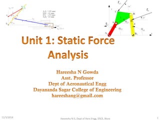
  • 2. Unit 1: Static Force Analysis • Static force analysis – Introduction – Static equilibrium – Equilibrium of two and three force members – Members with two forces and torque – Free body diagrams – principle of virtual work • Static force analysis of – four bar mechanism – slider-crank mechanism with and without friction. 6/19/2015 Hareesha N G, Dept of Aero Engg, DSCE, Blore 2
  • 3. STATIC EQUILIBRIUM • A body is in static equilibrium if it remains in its state of rest or motion. • If the body is at rest, it tends to remain at rest and if in motion, it tends to keep the motion. • In static equilibrium, – the vector sum of all the forces acting on the body is zero and – the vector sum of all the moments about any arbitrary point is zero. • Mathematically, • In a planer system, forces can be described by two-dimensional vectors and therefore, 6/19/2015 Hareesha N G, Dept of Aero Engg, DSCE, Blore 3
  • 4. EQUILIBRIUM OF TWO AND THREE-FORCE MEMBERS • A member under the action of two forces will be in equilibrium if – the forces are of the same magnitude, – the forces act along the same line, and – the forces are in opposite directions. • Figure shows such a member. • A member under the action of three forces will be in equilibrium if – the resultant of the forces is zero, and – the lines of action of the forces intersect at a point (known as point of concurrency). 6/19/2015 Hareesha N G, Dept of Aero Engg, DSCE, Blore 4
  • 5. EQUILIBRIUM OF TWO AND THREE-FORCE MEMBERS (Contd….) • Figure (a) shows a member acted upon by three forces F1, F2 and F3 and is in equilibrium as the lines of action of forces intersect at one point O and the resultant is zero. • This is verified by adding the forces vectorially [Fig.(b)]. • As the head of the last vector F3 meets the tail of the first vector F1, the resultant is zero. • Figure (d) shows a case where the magnitudes and directions of the forces are the same as before, but the lines of action of the forces do not intersect at one point. • Thus, the member is not in equilibrium. 6/19/2015 Hareesha N G, Dept of Aero Engg, DSCE, Blore 5
  • 6. • Consider a member in equilibrium in which force F1 is completely known, F2 known in direction only and F3 completely unknown. • The point of applications of F1 , F2 and F3 are A, B and C respectively. • To solve such a problem, first find the point of concurrency O from the two forces with known directions, i.e. from F1, and F2. • Joining O with C gives the line of action of the third force F3. • To know the magnitudes of the forces F2 and F3, take a vector of proper magnitude and direction to represent the force F1. • From its two ends, draw lines parallel to lines of action of the forces F2 and F3 forming a force triangle [Fig.]. • Mark arrowheads on F2 and F3 so that F1 , F2 and F3 are in the same order. 6/19/2015 Hareesha N G, Dept of Aero Engg, DSCE, Blore 6
  • 7. MEMBER WITH TWO FORCES AND A TORQUE • A member under the action of two forces and an applied torque will be in equilibrium if – the forces are equal in magnitude, parallel in direction and opposite in sense and – the forces form a couple which is equal and opposite to the applied torque. • Figure shows a member acted upon by two equal forces F1, and F2 and an applied torque T for equilibrium, where T, F1 and F2 are the magnitudes of T, F1 and F2 respectively. • T is clockwise whereas the couple formed by F1, and F2 is counter- clockwise. 6/19/2015 Hareesha N G, Dept of Aero Engg, DSCE, Blore 7
  • 8. FORCE CONVENTION • The force exerted by member i on member j is represented by Fij 6/19/2015 Hareesha N G, Dept of Aero Engg, DSCE, Blore 8
  • 9. FREE BODY DIAGRAMS • A free body diagram is a sketch or diagram of a part isolated from the mechanism in order to determine the nature of forces acting on it. • Figure (a) shows a four-link mechanism. • The free-body diagrams of its members 2, 3 and 4 are shown in Figs. (b), (c) and (d) respectively. • Various forces acting on each member are also shown. • As the mechanism is in static equilibrium, each of its members must be in equilibrium individually. 6/19/2015 Hareesha N G, Dept of Aero Engg, DSCE, Blore 9
  • 10. • Member 4 is acted upon by three forces F, F34 and F14. • Member 3 is acted upon by two forces F23 and F43 • Member 2 is acted upon by two forces F32 and F12 and a torque T. • Initially, the direction and the sense of some of the forces may not be known. • Link 3 is a two-force member and for its equilibrium F23 and F43 must act along BC. • Thus, F34 being equal and opposite to F43 also acts along BC. 6/19/2015 Hareesha N G, Dept of Aero Engg, DSCE, Blore 10
  • 11. • Assume that the force F on member 4 is known completely. • To know the other two forces acting on this member completely, the direction of one more force must be known. • For member 4 to be in equilibrium, F14 passes through the intersection of F and F34 . • By drawing a force triangle (F is completely known), magnitudes of F14 and F34 can be known [Fig.(e)]. Now F34 = F43 = F23 = F32 • Member 2 will be in equilibrium if F12 is equal, parallel and opposite to F32 and 6/19/2015 Hareesha N G, Dept of Aero Engg, DSCE, Blore 11
  • 12. A four-link mechanism with the following dimensions is acted upon by a force 80N at angle 1500 on link DC [Fig.(a)): AD = 50 mm, AB = 40 mm, BC = 100 mm, DC = 75 mm, DE = 35 mm. Determine the input torque T on the link AB for the static equilibrium of the mechanism for the given configuration. 6/19/2015 Hareesha N G, Dept of Aero Engg, DSCE, Blore 12 As the mechanism is in static equilibrium, each of its members must also be in equilibrium individually. Member 4 is acted upon by three forces F F34 and F14. Member 3 is acted upon by two forces F23 and F43 Member 2 is acted upon by two forces F32 and F12 and a torque T. Initially, the direction and the sense of some of the forces are not known. Force F on member 4 is known completely. To know the other two forces acting on this member completely, the direction of one more force must be known. To know that, link 3 will have to be considered first which is a two-force member.
  • 13. • As link 3 is a two-force member [Fig.(b)], for its equilibrium, F23 and F43 must act along BC (at this stage, the sense of direction of forces F23 and F43 is not known). Thus, the line of action of F34 is also along BC. • As force F34 acts through point C on link 4, draw a line parallel to BC through C by taking a free body of link 4 to represent the same. Now, as link 4 is three force member, the third force F14 passes through the intersection of F and F34 [Fig (c)]. • By drawing a force triangle (F is completely known), magnitudes of F14 and F34 are known [Fig(d)]. 6/19/2015 Hareesha N G, Dept of Aero Engg, DSCE, Blore 13 From force triangle, F34 = 47.8 N
  • 14. • Now, F34 = -F43 =F23 = -F32 • Member 2 will be in equilibrium [Fig. (e)] if F12 is equal, parallel and opposite to F32 and T=-F32 x h = 47.8 x 39.3 = -1878.54 N.mm The input torque has to be equal and opposite to this couple i.e. T= 1878.5 N/mm (clockwise) h=Perpendicular distance between two equal and opposite forces. 6/19/2015 Hareesha N G, Dept of Aero Engg, DSCE, Blore 14
  • 15. Figure shows a slider crank mechanism in which the resultant gas pressure 8x10⁴ N/m2 acts on the piston of cross sectional area 0.1m2 The system is kept in equilibrium as a result of the couple applied to the crank 2, through the shaft at O2. Determine forces acting on all the links (including the pins) and the couple on 2. OA=100mm, AB=450mm. 6/19/2015 Hareesha N G, Dept of Aero Engg, DSCE, Blore 15
  • 16. 6/19/2015 Hareesha N G, Dept of Aero Engg, DSCE, Blore 16 Force triangle for the forces acting on(4)is drawn to some suitable scale. Magnitude and direction of P known and lines of action of F34 & F14 known. Measure the lengths of vectors and multiply by the scale factor to get the magnitudes of F14 & F34. Directions are also fixed. Since link 3 is acted upon by only two forces, F43 and F23 are collinear, equal in magnitude and opposite in direction i.e., F43 = -F23 =8.8xl03 N Also, F23 = - F32 (equal in magnitude and opposite in direction).
  • 17. 6/19/2015 Hareesha N G, Dept of Aero Engg, DSCE, Blore 17 Link 2 is acted upon by 2 forces and a torque, for equilibrium the two forces must be equal, parallel and opposite and their sense must be opposite to T2. There fore, F32 = -F12 =8.8xl03 N F32 & F12 form a counter clock wise couple of magnitude, F23 * h = F12 *h =(8.8xl03)x0.125 = 1100 Nm. To keep 2 in equilibrium, T: should act clockwise and magnitude is 1100 Nm. Note: h is measured perpendicular to F32 &F12
  • 18. 6/19/2015 Hareesha N G, Dept of Aero Engg, DSCE, Blore 18 For the static equilibrium of the quick return mechanism shown in Fig (a), determine the input torque T2: to be applied on link AB Tor a force of 300N on the slider D. The dimensions of the various links arc OA=400mm, AB=200mm, OC=800mm. CD=300mm
  • 19. 6/19/2015 Hareesha N G, Dept of Aero Engg, DSCE, Blore 19
  • 20. • For the mechanism shown in Fig., determine the torque on the link AB for the static equilibrium of the mechanism. 6/19/2015 Hareesha N G, Dept of Aero Engg, DSCE, Blore 20
  • 21. • Answers from Composite Graphical Solution 6/19/2015 Hareesha N G, Dept of Aero Engg, DSCE, Blore 21
  • 22. Graphical Solution by Superposition method 6/19/2015 Hareesha N G, Dept of Aero Engg, DSCE, Blore 22
  • 23. Graphical Solution by Superposition method 6/19/2015 Hareesha N G, Dept of Aero Engg, DSCE, Blore 23
  • 24. In a four-link mechanism shown in Fig., torque T3 and T4 have magnitudes of 30N.m and2 ON. m respectively. The link lengths are AD = 800 mm, AB = 300 mm, BC = 700 mm and CD = 400 mm. For the static equilibrium of the mechanism, determine the required input torque T2 6/19/2015 Hareesha N G, Dept of Aero Engg, DSCE, Blore 24
  • 25. In a four-link mechanism shown in Fig., torque T3 and T4 have magnitudes of 30N.m and2 ON. m respectively. The link lengths are AD = 800 mm, AB = 300 mm, BC = 700 mm and CD = 400 mm. For the static equilibrium of the mechanism, determine the required input torque T2 6/19/2015 Hareesha N G, Dept of Aero Engg, DSCE, Blore 25
  • 26. 6/19/2015 Hareesha N G, Dept of Aero Engg, DSCE, Blore 26 Neglecting torque T3
  • 27. 6/19/2015 Hareesha N G, Dept of Aero Engg, DSCE, Blore 27 Neglecting torque T4
  • 28. PRINCIPLE OF VIRTUAL WORK • The principle of virtual (imaginary) work can be stated as the work done during a virtual displacement from the equilibrium is equal to zero. • Virtual displacement may be defined as an imaginary infinitesimal displacement of the system. • By applying this principle, an entire mechanism is examined as a whole and there is no need of dividing it into free bodies. 6/19/2015 Hareesha N G, Dept of Aero Engg, DSCE, Blore 28
  • 29. • Consider a slider-crank mechanism shown in Fig. • It is acted upon by the external piston force F, the external crankshaft torque T and the force at the bearings. • As the crank rotates through a small angular displacement δθ, the corresponding displacement of the piston is δx, the various forces acting on the system are – Bearing reaction at O (performs no work) – Force of cylinder on piston, perpendicular to piston displacement (produces no work) – Bearing forces at A and B, being equal and opposite (AB is a two-force member), no work is done – Work done by torque T= T δθ – Work done by force F = F δx • Work done is positive if a force acts in the direction of the displacement and negative if it acts in the opposite direction. 6/19/2015 Hareesha N G, Dept of Aero Engg, DSCE, Blore 29
  • 30. The negative sign indicates that for equilibrium, T must be applied in the opposite direction to the angular displacement. 6/19/2015 Hareesha N G, Dept of Aero Engg, DSCE, Blore 30
  • 31. 6/19/2015 Hareesha N G, Dept of Aero Engg, DSCE, Blore 31
  • 32. 6/19/2015 Hareesha N G, Dept of Aero Engg, DSCE, Blore 32