
Empfohlen
Weitere ähnliche Inhalte
Ähnlich wie M5 Xd812
Ähnlich wie M5 Xd812 (20)
Kürzlich hochgeladen
Kürzlich hochgeladen (20)
M5 Xd812
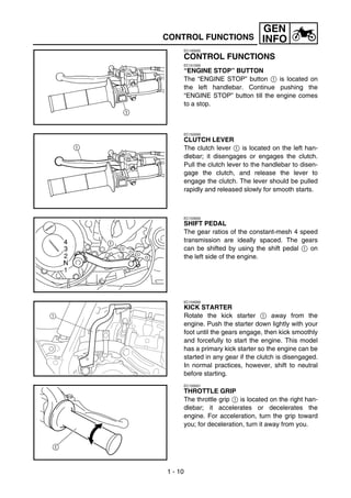
- 1. GEN CONTROL FUNCTIONS INFO EC150000 CONTROL FUNCTIONS EC151000 “ENGINE STOP” BUTTON The “ENGINE STOP” button 1 is located on the left handlebar. Continue pushing the “ENGINE STOP” button till the engine comes to a stop. EC152000 CLUTCH LEVER The clutch lever 1 is located on the left han- dlebar; it disengages or engages the clutch. Pull the clutch lever to the handlebar to disen- gage the clutch, and release the lever to engage the clutch. The lever should be pulled rapidly and released slowly for smooth starts. EC153000 SHIFT PEDAL The gear ratios of the constant-mesh 4 speed transmission are ideally spaced. The gears can be shifted by using the shift pedal 1 on the left side of the engine. EC154000 KICK STARTER 1 Rotate the kick starter 1 away from the engine. Push the starter down lightly with your foot until the gears engage, then kick smoothly and forcefully to start the engine. This model has a primary kick starter so the engine can be started in any gear if the clutch is disengaged. In normal practices, however, shift to neutral before starting. EC155001 THROTTLE GRIP The throttle grip 1 is located on the right han- dlebar; it accelerates or decelerates the engine. For acceleration, turn the grip toward you; for deceleration, turn it away from you. 1 - 10
- 2. GEN CONTROL FUNCTIONS INFO EC156000 FRONT BRAKE LEVER The front brake lever 1 is located on the right handlebar. Pull it toward the handlebar to acti- vate the front brake. EC157000 REAR BRAKE PEDAL The rear brake pedal 1 is located on the right side of the machine. Press down on the brake pedal to activate the rear brake. EC158001 FUEL COCK The fuel cock supplies fuel from the tank to carburetor while filtering the fuel. The fuel cock has the two positions: OFF: With the lever in this position, fuel will not flow. Always return the lever to this posi- tion when the engine is not running. ON: With the lever in this position, fuel flows to the carburetor. Normal riding is done with the lever in this position. COLD STARTER KNOB When cold, the engine requires a richer air-fuel mixture for starting. A separate starter circuit, which is controlled by the cold starter knob 1, supplies this mixture. Pull the cold starter knob out to open the circuit for starting. When the engine has warmed up, push it in to close the circuit. HOT STARTER LEVER The hot starter lever 1 is used when starting a warm engine. Use the hot starter lever when starting the engine again immediately after it was stopped (the engine is still warm). Pulling the hot starter lever injects secondary air to thin the air-fuel mixture temporarily, allowing the engine to be started more easily. 1 - 11
- 3. GEN CONTROL FUNCTIONS INFO EC15R001 DETACHABLE SIDESTAND This sidestand 1 is used to support only the machine when standing or transporting it. WARNING • Never apply additional force to the side- stand. • Remove this sidestand before starting out. EC15F000 VALVE JOINT This valve joint 1 prevents fuel from flowing out and is installed to the fuel tank breather hose. CAUTION: In this installation, make sure the arrow faces the fuel tank and also downward. SPARK PLUG WRENCH This spark plug wrench 1 is used to remove 1 and install the spark plug. 1 NIPPLE WRENCH This nipple wrench 1 is used to tighten the spoke. 1 - 12
- 4. GEN STARTING AND BREAK-IN INFO 6. Return the cold starter knob to its original position and run the engine at 3,000 ~ 5,000 r/min for 1 or 2 minutes. NOTE: Since this model is equipped with an accelera- tor pump, if the engine is raced (the throttle opened and closed), the air/fuel mixture will be too rich and the engine may stall. Also unlike a two-stroke engine, this model can idle. CAUTION: Do not warm up the engine for extended periods of time. 1 - 15
- 5. GEN STARTING AND BREAK-IN INFO STARTING A WARM ENGINE Do not operate the cold starter knob and throt- tle. Pull the hot starter lever 1 and start the engine by kicking the kick starter forcefully with a firm stroke. As soon as the engine starts, release the hot starter lever to close the air passage. Restarting an engine after a fall Pull the hot starter lever and start the engine. As soon as the engine starts, release the hot starter lever to close the air passage. The engine fails to start Pull the hot starter lever all the way out and while holding the lever, kick the kick starter 10 to 20 times to clear the engine. Then, restart the engine. Refer to “Restarting an engine after a fall”. Throttle Cold Hot grip oper- starter starter ation* knob lever Air temperature = less than Open 3 ON OFF or 4 times Starting a cold engine 5 °C (41 °F) Air temperature = more None ON OFF than 5 °C (41 °F) Air temperature (normal tem- perature) = between 5 °C None ON/OFF OFF (41 °F) and 25 °C (77 °F) Air temperature = more None OFF OFF than 25 °C (77 °F) Starting an engine after a long None ON OFF period of time Restarting a warm engine None OFF ON Restarting an engine after a fall None OFF ON * Operate the throttle grip before kick starting. CAUTION: Observe the following break-in procedures during initial operation to ensure optimum performance and avoid engine damage. 1 - 16
- 6. GENERAL SPECIFICATIONS SPEC EC200000 SPECIFICATIONS EC211000 GENERAL SPECIFICATIONS Model name: YZ450FT (USA, CDN, AUS, NZ) YZ450F (EUROPE, ZA) Model code number: 5XD5 (USA) 5XD6 (EUROPE) 5XD8 (CDN, AUS, NZ, ZA) Dimensions: USA, ZA, EUR F, CDN AUS, NZ (Except for F) Overall length 2,190 mm 2,195 mm ← (86.2 in) (86.4 in) Overall width 827 mm ← ← (32.6 in) Overall height 1,300 mm 1,302 mm 1,303 mm (51.2 in) (51.3 in) (51.3 in) Seat height 999 mm 1,001 mm ← (39.3 in) (39.4 in) Wheelbase 1,493 mm ← ← (58.8 in) Minimum ground clearance 379 mm 381 mm ← (14.9 in) (15.0 in) Dry weight: Without oil and fuel 100.0 kg (220 lb) Engine: Engine type Liquid cooled 4-stroke, DOHC Cylinder arrangement Single cylinder, forward inclined Displacement 449 cm3 (15.8 Imp oz, 15.2 US oz) Bore × stroke 95.0 × 63.4 mm (3.74 × 2.50 in) Compression ratio 12.3 : 1 Starting system Kick starter Lubrication system: Dry sump 2-1
- 7. GENERAL SPECIFICATIONS SPEC Oil type or grade: Engine oil (For USA and CDN) At 5 °C (40 °F) or higher È Yamalube 4 (20W-40) or SAE 20W-40 type SG motor oil (Non-Friction modified) At 15 °C (60 °F) or lower É Yamalube 4 (10W-30) or SAE 10W-30 type SG motor oil (Non-Friction modified) and/or Yamalube 4-R (15W-50) (Non-Friction modi- fied) -20 -10 Temp. 0 10 20 30 40 50 ˚C (Except for USA and CDN) API “SG” or higher grade 2 10W-30 10W-40 15W-40 20W-40 20W-50 -4 14 30 50 68 86 104 122 ˚F Oil capacity: Engine oil Periodic oil change 1.0 L (0.88 Imp qt, 1.06 US qt) With oil filter replacement 1.1 L (0.97 Imp qt, 1.16 US qt) Total amount 1.2 L (1.06 Imp qt, 1.27 US qt) Coolant capacity (including all routes): 1.2 L (1.06 Imp qt, 1.27 US qt) Air filter: Wet type element Fuel: Type Premium unleaded gasoline only with a research octane number of 95 or higher. Tank capacity 7.0 L (1.54 Imp gal, 1.85 US gal) Carburetor: Type FCR MX39 Manufacturer KEIHIN Spark plug: Type/manufacturer CR8E/NGK (resistance type) Gap 0.7 ~ 0.8 mm (0.028 ~ 0.031 in) Clutch type: Wet, multiple-disc 2-2
- 8. GENERAL SPECIFICATIONS SPEC Transmission: Primary reduction system Gear Primary reduction ratio 61/23 (2.652) Secondary reduction system Chain drive Secondary reduction ratio 51/14 (3.643) Transmission type Constant mesh, 4-speed Operation Left foot operation Gear ratio: 1st 27/14 (1.929) 2nd 25/16 (1.563) 3rd 23/18 (1.278) 4th 21/20 (1.050) Chassis: Frame type Semi double cradle Caster angle 27.1° Trail 116 mm (4.57 in) (For USA, ZA, AUS, NZ) 117 mm (4.61 in) (For EUROPE except F) 118 mm (4.65 in) (For F, CDN) Tire: Type With tube Size (front) 80/100-21 51M (For USA, CDN, ZA, AUS, NZ and F) 80/100-21 51R (For EUROPE except F) Size (rear) 110/90-19 62M (For USA, CDN, ZA, AUS, NZ and F) 110/90-19 NHS (For EUROPE except F) Tire pressure (front and rear) 100 kPa (1.0 kgf/cm2, 15 psi) Brake: Front brake type Single disc brake Operation Right hand operation Rear brake type Single disc brake Operation Right foot operation Suspension: Front suspension Telescopic fork Rear suspension Swingarm (link type monocross suspension) Shock absorber: Front shock absorber Coil spring/oil damper Rear shock absorber Coil spring/gas, oil damper Wheel travel: Front wheel travel 300 mm (11.8 in) Rear wheel travel 315 mm (12.4 in) Electrical: Ignition system CDI magneto 2-3
- 9. MAINTENANCE SPECIFICATIONS SPEC MAINTENANCE SPECIFICATIONS ENGINE Item Standard Limit Cylinder head: Warp limit ---- 0.05 mm (0.002 in) Cylinder: Bore size 95.00 ~ 95.01 mm ---- (3.7402 ~ 3.7406 in) Out of round limit ---- 0.05 mm (0.002 in) Camshaft: Drive method Chain drive (Left) ---- Camshaft cap inside diameter 22.000 ~ 22.021 mm ---- (0.8661 ~ 0.8670 in) Camshaft journal diameter 21.967 ~ 21.980 mm ---- (0.8648 ~ 0.8654 in) Shaft-to-cap clearance 0.020 ~ 0.054 mm 0.08 mm (0.0008 ~ 0.0021 in) (0.003 in) Cam dimensions A B Intake “A” 31.200 ~ 31.300 mm 31.100 mm (1.2283 ~ 1.2323 in) (1.2244 in) “B” 22.550 ~ 22.650 mm 22.450 mm (0.8878 ~ 0.8917 in) (0.8839 in) Exhaust “A” 30.950 ~ 31.050 mm 30.850 mm (1.2185 ~ 1.2224 in) (1.2146 in) “B” 22.494 ~ 22.594 mm 22.394 mm (0.8856 ~ 0.8895 in) (0.8817 in) Camshaft runout limit ---- 0.03 mm (0.0012 in) 2-4
- 10. MAINTENANCE SPECIFICATIONS SPEC Item Standard Limit Cam chain: Cam chain type/No. of links 98XRH2010-118M/118 ---- Cam chain adjustment method Automatic ---- Valve, valve seat, valve guide: Valve clearance (cold) IN 0.10 ~ 0.15 mm ---- (0.0039 ~ 0.0059 in) EX 0.20 ~ 0.25 mm ---- (0.0079 ~ 0.0098 in) Valve dimensions: B C D A Head Diameter Face Width Seat Width Margin Thickness “A” head diameter IN 26.9 ~ 27.1 mm ---- (1.0591 ~ 1.0669 in) EX 27.9 ~ 28.1 mm ---- (1.0984 ~ 1.1063 in) “B” face width IN 2.26 mm (0.089 in) ---- EX 2.26 mm (0.089 in) ---- “C” seat width IN 0.9 ~ 1.1 mm 1.6 mm (0.0354 ~ 0.0433 in) (0.0630 in) EX 0.9 ~ 1.1 mm 1.6 mm (0.0354 ~ 0.0433 in) (0.0630 in) “D” margin thickness IN 1 mm (0.0394 in) 0.85 mm (0.033 in) EX 1 mm (0.0394 in) 0.85 mm (0.033 in) Stem outside diameter IN 4.475 ~ 4.490 mm 4.445 mm (0.1762 ~ 0.1768 in) (0.1750 in) EX 4.965 ~ 4.980 mm 4.935 mm (0.1955 ~ 0.1961 in) (0.1943 in) Guide inside diameter IN 4.500 ~ 4.512 mm 4.550 mm (0.1772 ~ 0.1776 in) (0.1791 in) EX 5.000 ~ 5.012 mm 5.050 mm (0.1969 ~ 0.1973 in) (0.1988 in) Stem-to-guide clearance IN 0.010 ~ 0.037 mm 0.08 mm (0.0004 ~ 0.0015 in) (0.003 in) EX 0.020 ~ 0.047 mm 0.10 mm (0.0008 ~ 0.0019 in) (0.004 in) Stem runout limit ---- 0.01 mm (0.0004 in) 2-5
- 11. MAINTENANCE SPECIFICATIONS SPEC Item Standard Limit Valve spring: Free length IN 37.03 mm (1.46 in) 36.03 mm (1.42 in) EX 37.68 mm (1.48 in) 36.68 mm (1.44 in) Set length (valve closed) IN 27.87 mm (1.10 in) ---- EX 27.38 mm (1.08 in) ---- Compressed force (installed) IN 111.3 ~ 127.9 N at 27.87 mm ---- (11.3 ~ 13.0 kg at 27.87 mm, 24.91 ~ 28.66 lb at 1.10 in) EX 127.4 ~ 146.4 N at 27.38 mm ---- (13.0 ~ 14.9 kg at 27.38 mm, 28.66 ~ 32.85 lb at 1.08 in) Tilt limit IN ---- 2.5°/1.61 mm (2.5°/0.063 in) EX ---- 2.5°/1.65 mm (2.5°/0.065 in) Direction of winding (top view) IN Clockwise ---- EX Clockwise ---- Piston: Piston to cylinder clearance 0.040 ~ 0.065 mm 0.1 mm (0.0016 ~ 0.0026 in) (0.004 in) Piston size “D” 94.945 ~ 94.960 mm ---- (3.738 ~ 3.739 in) H D Measuring point “H” 8 mm (0.315 in) ---- Piston off-set 1 mm (0.0394 in) ---- Piston pin bore inside diameter 18.004 ~ 18.015 mm 18.045 mm (0.7088 ~ 0.7093 in) (0.7104 in) Piston pin outside diameter 17.991 ~ 18.000 mm 17.971 mm (0.7083 ~ 0.7087 in) (0.7075 in) 2-6
- 12. MAINTENANCE SPECIFICATIONS SPEC Item Standard Limit Piston rings: Top ring: B T Type Barrel ---- Dimensions (B × T) 1.2 × 3.5 mm (0.05 × 0.14 in) ---- End gap (installed) 0.20 ~ 0.30 mm 0.55 mm (0.008 ~ 0.012 in) (0.022 in) Side clearance (installed) 0.030 ~ 0.065 mm 0.12 mm (0.0012 ~ 0.0026 in) (0.005 in) 2nd ring: B T Type Taper ---- Dimensions (B × T) 1.00 × 3.35 mm (0.04 × 0.13 in) ---- End gap (installed) 0.35 ~ 0.50 mm 0.85 mm (0.014 ~ 0.020 in) (0.033 in) Side clearance 0.020 ~ 0.055 mm 0.12 mm (0.0008 ~ 0.0022 in) (0.005 in) Oil ring: B T Dimensions (B × T) 2.0 × 2.9 mm (0.08 × 0.11 in) ---- End gap (installed) 0.2 ~ 0.5 mm (0.01 ~ 0.02 in) ---- Crankshaft: Crank width “A” 61.95 ~ 62.00 mm ---- (2.439 ~ 2.441 in) Runout limit “C” 0.03 mm (0.0012 in) 0.05 mm (0.002 in) Big end side clearance “D” 0.15 ~ 0.45 mm 0.50 mm (0.0059 ~ 0.0177 in) (0.02 in) Small end free play “F” 0.4 ~ 1.0 mm (0.02 ~ 0.04 in) 2.0 mm (0.08 in) Balancer: Balancer drive method Gear ---- Air filter oil grade: Foam-air-filter oil or equivalent ---- oil 2-7
- 13. MAINTENANCE SPECIFICATIONS SPEC Item Standard Limit Clutch: Friction plate thickness 2.92 ~ 3.08 mm 2.8 mm (0.115 ~ 0.121 in) (0.110 in) Quantity 9 ---- Clutch plate thickness 1.1 ~ 1.3 mm (0.043 ~ 0.051 in) ---- Quantity 8 ---- Warp limit ---- 0.1 mm (0.004 in) Clutch spring free length 47.8 mm (1.88 in) 46.8 mm (1.84 in) Quantity 6 ---- Clutch housing thrust clearance 0.10 ~ 0.35 mm ---- (0.0039 ~ 0.0138 in) Clutch housing radial clearance 0.010 ~ 0.044 mm ---- (0.0004 ~ 0.0017 in) Clutch release method Inner push, cam push ---- Shifter: Shifter type Cam drum and guide bar ---- Guide bar bending limit ---- 0.05 mm (0.002 in) Kick starter: Type Ratchet type ---- Carburetor: I.D. mark 5XD5 50 ---- Main jet (M.J) #165 ---- Main air jet (M.A.J) ø2.0 ---- Jet needle - clip position (J.N) NFLR-4 ---- Cutaway (C.A) 1.5 ---- Pilot jet (P.J) #45 ---- Pilot air jet (P.A.J) #100 ---- Pilot outlet (P.O) ø0.9 ---- Pilot screw (example) (P.S) 1-3/4 ---- Bypass (B.P) ø1.0 ---- Valve seat size (V.S) ø3.8 ---- Starter jet (G.S) #72 ---- Leak jet (Acc. P) #40 ---- Float height (F.H) 8 mm (0.31 in) ---- Engine idle speed 1,900 ~ 2,100 r/min ---- Intake vacuum 28.0 ~ 33.3 kPa ---- (210 ~ 250 mmHg, 8.27 ~ 9.84 inHg) Hot starter lever free play 3 ~ 6 mm (0.12 ~ 0.24 in) ---- 2-8
- 14. MAINTENANCE SPECIFICATIONS SPEC Item Standard Limit Lubrication system: Oil filter type Paper type ---- Oil pump type Trochoid type ---- Tip clearance “A” 0.12 mm or less 0.20 mm (0.0047 in or less) (0.008 in) Tip clearance “B” 0.09 ~ 0.17 mm 0.24 mm (0.0035 ~ 0.0067 in) (0.009 in) Side clearance 0.03 ~ 0.10 mm 0.17 mm (0.0012 ~ 0.0039 in) (0.007 in) Bypass valve setting pressure 40 ~ 80 kPa (0.4 ~ 0.8 kg/cm2, ---- 5.69 ~ 11.38 psi) Cooling: Radiator core size Width 117.8 mm (4.6 in) ---- Height 260 mm (10.2 in) ---- Thickness 32 mm (1.26 in) ---- Radiator cap opening pressure 110 kPa (1.1 kg/cm2, 15.6 psi) ---- Radiator capacity (total) 0.71 L (0.62 Imp qt, 0.75 US qt) ---- Water pump Type Single-suction centrifugal pump ---- 2-9
- 15. MAINTENANCE SPECIFICATIONS SPEC Item Standard Lubrication chart: Pressure feed Oil tank Splashed scavenge Camshaft Cylinder head Valve lifter Piston Transmission gears Piston pin Main axle Oil filter Crank pin Drive axle Check ball Oil pump rotor 1 Oil pump rotor 2 Oil strainer Oil pan 2 - 10
- 16. MAINTENANCE SPECIFICATIONS SPEC Tightening torque Part to be tightened Thread size Q’ty Nm m·kg ft·lb Spark plug M10S × 1.0 1 13 1.3 9.4 Camshaft cap M6 × 1.0 10 10 1.0 7.2 Cylinder head blind plug screw M12 × 1.0 1 28 2.8 20 Cylinder head (stud bolt) M6 × 1.0 2 7 0.7 5.1 M8 × 1.25 1 15 1.5 11 (bolt) M10 × 1.25 4 Refer to NOTE.*1 (nut) M6 × 1.0 2 10 1.0 7.2 Cylinder head cover M6 × 1.0 2 10 1.0 7.2 Cylinder M6 × 1.0 1 10 1.0 7.2 Timing chain tensioner M6 × 1.0 2 10 1.0 7.2 Tensioner cap bolt M6 × 1.0 1 7 0.7 5.1 Timing chain guide (rear) M6 × 1.0 2 10 1.0 7.2 Exhaust pipe (nut) M8 × 1.25 1 13 1.3 9.4 (bolt) M8 × 1.25 1 24 2.4 17 Silencer M8 × 1.25 2 35 3.5 25 Silencer clamp M8 × 1.25 1 16 1.6 11 Exhaust pipe protector M6 × 1.0 3 10 1.0 7.2 Clamp (cylinder head side) M5 × 0.8 1 3 0.3 2.2 Clamp (carburetor side) M4 × 0.7 1 3 0.3 2.2 Air filter case M6 × 1.0 2 8 0.8 5.8 Air filter joint clamp M6 × 1.0 1 3 0.3 2.2 Air filter joint and air filter case M5 × 0.8 1 4 0.4 2.9 Throttle cable (pull) M6 × 1.0 1 4 0.4 2.9 Throttle cable (return) M12 × 1.0 1 11 1.1 8.0 Throttle cable cover M5 × 0.8 2 4 0.4 2.9 Hot starter plunger M12 × 1.0 1 2 0.2 1.4 Air filter element M6 × 1.0 1 2 0.2 1.4 Radiator panel (upper) M6 × 1.0 2 10 1.0 7.2 Radiator M6 × 1.0 6 10 1.0 7.2 Radiator hose clamp M6 × 1.0 8 2 0.2 1.4 Radiator pipe 1, 2 M10 × 1.0 2 10 1.0 7.2 Impeller M8 × 1.25 1 14 1.4 10 Water pump housing cover M6 × 1.0 3 10 1.0 7.2 Coolant drain bolt M6 × 1.0 1 10 1.0 7.2 Oil pump cover M4 × 0.7 1 2 0.2 1.4 Oil pump M6 × 1.0 3 9 0.9 6.5 Engine oil drain bolt (oil filter) M6 × 1.0 1 10 1.0 7.2 Oil filter cover M6 × 1.0 2 10 1.0 7.2 Oil delivery pipe 1 M10 × 1.25 1 20 2.0 14 M8 × 1.25 2 18 1.8 13 Oil delivery pipe 2 M6 × 1.0 1 10 1.0 7.2 Oil hose M6 × 1.0 2 8 0.8 5.8 Oil check bolt M6 × 1.0 1 10 1.0 7.2 2 - 11
- 17. MAINTENANCE SPECIFICATIONS SPEC Tightening torque Part to be tightened Thread size Q’ty Nm m·kg ft·lb Oil hose clamp — 2 2 0.2 1.4 Clutch cover M6 × 1.0 7 10 1.0 7.2 Crankcase cover (right) M6 × 1.0 10 10 1.0 7.2 Crankcase cover (left) M6 × 1.0 8 10 1.0 7.2 Crankcase M6 × 1.0 12 12 1.2 8.7 Clutch cable holder M6 × 1.0 1 10 1.0 7.2 Oil drain bolt (crankcase rear) M10 × 1.25 1 20 2.0 14 (crankcase left) M6 × 1.0 1 10 1.0 7.2 Oil drain bolt (frame) M8 × 1.25 1 23 2.3 17 Oil strainer (frame) M14 × 1.5 1 70 7.0 50 Crankcase bearing stopper M6 × 1.0 15 10 1.0 7.2 Drive axle oil seal stopper M6 × 1.0 2 10 1.0 7.2 Ratchet wheel guide M6 × 1.0 2 12 1.2 8.7 Kick starter M8 × 1.25 1 33 3.3 24 Screw (kick starter) M6 × 1.0 1 7 0.7 5.1 Primary drive gear M20 × 1.0 1 110 11.0 80 Clutch boss M20 × 1.0 1 75 7.5 54 Clutch cable locknut M8 × 1.25 2 7 0.7 5.1 Push lever M6 × 1.0 1 10 1.0 7.2 Clutch spring M6 × 1.0 6 8 0.8 5.8 Balancer driven gear M14 × 1.0 1 50 5.0 36 Balancer weight plate M6 × 1.0 3 10 1.0 7.2 Drive sprocket M20 × 1.0 1 75 7.5 54 Drive sprocket cover M6 × 1.0 2 8 0.8 5.8 Shift pedal M6 × 1.0 1 12 1.2 8.7 Shift guide M6 × 1.0 2 10 1.0 7.2 Stopper lever M6 × 1.0 1 10 1.0 7.2 Segment M8 × 1.25 1 30 3.0 22 NOTE: - marked portion shall be checked for torque tightening after break-in or before each race. NOTE: *1: Tighten the cylinder head bolts to 30 Nm (3.0 m • kg, 22 ft • lb) in the proper tightening sequence, remove and retighten the cylinder head bolts to 20 Nm (2.0 m • kg, 14 ft • lb) in the proper tightening sequence, and then tighten the cylinder head bolts further to reach the specified angle 180° in the proper tightening sequence. 2 - 12
- 18. MAINTENANCE SPECIFICATIONS SPEC EC212201 CHASSIS Item Standard Limit Steering system: Steering bearing type Taper roller bearing ---- Front suspension: USA, CDN, EUROPE AUS, NZ, ZA Front fork travel 300 mm (11.8 in) ← ---- Fork spring free length 465 mm (18.3 in) ← 460 mm (18.1 in) Spring rate, STD K = 4.5 N/mm K = 4.4 N/mm ---- (0.459 kg/mm, (0.449 kg/mm, 25.7 lb/in) 25.1 lb/in) Optional spring/spacer Yes ← ---- 3 Oil capacity 445 cm 455 cm3 ---- (15.7 Imp oz, (16.0 Imp oz, 15.0 US oz) 15.4 US oz) Oil grade Suspension oil ← ---- “S1” Inner tube outer diameter 48 mm (1.89 in) ← ---- Front fork top end Zero mm (Zero in) ← ---- Rear suspension: USA, CDN, EUROPE AUS, NZ, ZA Shock absorber travel 132 mm ← ---- (5.20 in) Spring free length 260 mm ← ---- (10.24 in) Fitting length 248 mm 245 mm ---- (9.76 in) (9.65 in) <Min.~Max.> 240.5 ~ 258.5 mm ← ---- (9.47 ~ 10.18 in) Spring rate, STD K = 52.0 N/mm K = 50.0 N/mm ---- (5.30 kg/mm, (5.10 kg/mm, 296.8 lb/in) 285.6 lb/in) Optional spring Yes ← ---- Enclosed gas pressure 1,000 kPa ← ---- (10 kg/cm2, 142 psi) Swingarm: Swingarm free play limit End ---- 1.0 mm (0.04 in) 2 - 13
- 19. MAINTENANCE SPECIFICATIONS SPEC Item Standard Limit Wheel: Front wheel type Spoke wheel ---- Rear wheel type Spoke wheel ---- Front rim size/material 21 × 1.60/Aluminum ---- Rear rim size/material 19 × 2.15/Aluminum ---- Rim runout limit: Radial ---- 2.0 mm (0.08 in) Lateral ---- 2.0 mm (0.08 in) Drive chain: Type/manufacturer DID520DMA2 SDH/DAIDO ---- Number of links 115 links + joint ---- Chain slack 48 ~ 58 mm (1.9 ~ 2.3 in) ---- Chain length (15 links) ---- 242.9 mm (9.563 in) Front disc brake: Disc outside dia. × Thickness 250 × 3.0 mm (9.84 × 0.12 in) 250 × 2.5 mm (9.84 × 0.10 in) Pad thickness 4.4 mm (0.17 in) 1.0 mm (0.04 in) Master cylinder inside dia. 11.0 mm (0.433 in) ---- Caliper cylinder inside dia. 27.0 mm (1.063 in) × 2 ---- Brake fluid type DOT #4 ---- Rear disc brake: Disc outside dia. × Thickness 245 × 4.0 mm (9.65 × 0.16 in) 245 × 3.5 mm (9.65 × 0.14 in) Deflection limit ---- 0.15 mm (0.006 in) Pad thickness 6.4 mm (0.25 in) 1.0 mm (0.04 in) Master cylinder inside dia. 11.0 mm (0.433 in) ---- Caliper cylinder inside dia. 25.4 mm (1.000 in) × 1 ---- Brake fluid type DOT #4 ---- Brake lever and brake pedal: Brake lever position 95 mm (3.74 in) ---- Brake pedal height 5 mm (0.20 in) ---- (vertical height above footrest top) Clutch lever free play (lever end) 8 ~ 13 mm (0.31 ~ 0.51 in) ---- Throttle grip free play 3 ~ 5 mm (0.12 ~ 0.20 in) ---- 2 - 14
- 20. MAINTENANCE SPECIFICATIONS SPEC Tightening torque Part to be tightened Thread size Q’ty Nm m·kg ft·lb Handle crown and outer tube M8 × 1.25 4 23 2.3 17 Under bracket and outer tube M8 × 1.25 4 20 2.0 14 Handle crown and steering shaft M24 × 1.0 1 145 14.5 105 Handlebar holder (upper) M8 × 1.25 4 28 2.8 20 Steering ring nut M28 × 1.0 1 Refer to NOTE. Front fork and damper assembly M51 × 1.5 2 30 3.0 22 Front fork and adjuster M22 × 1.25 2 55 5.5 40 Damper assembly and base valve M42 × 1.5 2 29 2.9 21 Adjuster and damper assembly M12 × 1.25 2 29 2.9 21 Bleed screw (front fork) and base valve M5 × 0.8 2 1 0.1 0.7 Front fork and protector M6 × 1.0 6 10 1.0 7.2 Protector and brake hose holder M6 × 1.0 2 7 0.7 5.1 Throttle cable cap M5 × 0.8 2 4 0.4 2.9 Clutch lever holder mounting M5 × 0.8 2 4 0.4 2.9 Clutch lever mounting (nut) M6 × 1.0 1 4 0.4 2.9 Hot starter lever holder mounting M5 × 0.8 2 4 0.4 2.9 Front brake master cylinder and bracket M6 × 1.0 2 9 0.9 6.5 Front brake master cylinder cap M4 × 0.7 2 2 0.2 1.4 Brake lever mounting (bolt) M6 × 1.0 1 6 0.6 4.3 Brake lever mounting (nut) M6 × 1.0 1 6 0.6 4.3 Brake lever position locknut M6 × 1.0 1 5 0.5 3.6 Cable guide (front brake hose) and under M6 × 1.0 1 4 0.4 2.9 bracket Front brake hose union bolt (master cylinder) M10 × 1.25 1 30 3.0 22 Front brake hose union bolt (caliper) M10 × 1.25 1 30 3.0 22 Front brake caliper and front fork M8 × 1.25 2 23 2.3 17 Front brake caliper and brake hose holder M6 × 1.0 1 10 1.0 7.2 Brake caliper (front and rear) and pad pin plug M10 × 1.0 2 3 0.3 2.2 Brake caliper (front and rear) and pad pin M10 × 1.0 2 18 1.8 13 Brake caliper (front and rear) and bleed screw M8 × 1.25 2 6 0.6 4.3 Front wheel axle and nut M16 × 1.5 1 105 10.5 75 Front wheel axle holder M8 × 1.25 4 23 2.3 17 Front brake disc and wheel hub M6 × 1.0 6 12 1.2 8.7 Rear brake disc and wheel hub M6 × 1.0 6 14 1.4 10 Brake pedal mounting M8 × 1.25 1 26 2.6 19 Rear brake master cylinder and frame M6 × 1.0 2 11 1.1 8.0 Rear brake master cylinder cap M4 × 0.7 2 2 0.2 1.4 Rear brake hose union bolt (caliper) M10 × 1.25 1 30 3.0 22 Rear brake hose union bolt (master cylinder) M10 × 1.25 1 30 3.0 22 NOTE: 1. First, tighten the ring nut approximately 38 Nm (3.8 m • kg, 27 ft • lb) by using the ring nut wrench, then loosen the ring nut one turn. 2. Retighten the ring nut 7 Nm (0.7 m • kg, 5.1 ft • lb). 2 - 15
- 21. MAINTENANCE SPECIFICATIONS SPEC Tightening torque Part to be tightened Thread size Q’ty Nm m·kg ft·lb Rear wheel axle and nut M20 × 1.5 1 125 12.5 90 Driven sprocket and wheel hub M8 × 1.25 6 42 4.2 30 Nipple (spoke) — 72 3 0.3 2.2 Disc cover and rear brake caliper M6 × 1.0 2 7 0.7 5.1 Protector and rear brake caliper M6 × 1.0 2 7 0.7 5.1 Chain puller adjust bolt and locknut M8 × 1.25 2 16 1.6 11 Engine mounting: Engine upper bracket and frame M10 × 1.25 2 55 5.5 40 Engine lower bracket and frame M8 × 1.25 4 34 3.4 24 Engine and engine bracket (front) M10 × 1.25 1 69 6.9 50 Engine and engine bracket (upper) M10 × 1.25 1 55 5.5 40 Engine and frame (lower) M10 × 1.25 1 69 6.9 50 Engine guard (lower) M8 × 1.25 1 34 3.4 24 Engine skid plate mounting M6 × 1.0 6 10 1.0 7.2 CDI unit bracket mounting M6 × 1.0 1 10 1.0 7.2 Pivot shaft and nut M16 × 1.5 1 85 8.5 61 Relay arm and swingarm M14 × 1.5 1 80 8.0 58 Relay arm and connecting rod M14 × 1.5 1 80 8.0 58 Connecting rod and frame M14 × 1.5 1 80 8.0 58 Rear shock absorber and frame M10 × 1.25 1 56 5.6 40 Rear shock absorber and relay arm M10 × 1.25 1 53 5.3 38 Rear frame and frame (upper) M8 × 1.25 1 32 3.2 23 Rear frame and frame (lower) M8 × 1.25 2 29 2.9 21 Swingarm and brake hose holder M5 × 0.8 4 1 0.1 0.7 Swingarm and patch M4 × 0.7 4 2 0.2 1.4 Drive chain tensioner mounting (upper) M8 × 1.25 1 19 1.9 13 Drive chain tensioner mounting (lower) M8 × 1.25 1 20 2.0 14 Chain support and swingarm M6 × 1.0 3 7 0.7 5.1 Seal guard and swingarm M5 × 0.8 4 6 0.6 4.3 Fuel tank mounting M6 × 1.0 2 10 1.0 7.2 Fuel tank and fuel cock M6 × 1.0 2 7 0.7 5.1 Fuel tank and seat set bracket M6 × 1.0 1 7 0.7 5.1 Fuel tank and hooking screw (fitting band) M6 × 1.0 1 7 0.7 5.1 Fuel tank and fuel tank bracket M6 × 1.0 4 7 0.7 5.1 Seat mounting M8 × 1.25 2 23 2.3 17 Side cover mounting M6 × 1.0 2 7 0.7 5.1 Air scoop and fuel tank M6 × 1.0 6 7 0.7 5.1 Air scoop and radiator panel (lower) M6 × 1.0 2 6 0.6 4.3 Front fender mounting M6 × 1.0 4 7 0.7 5.1 Rear fender mounting (front) M6 × 1.0 2 7 0.7 5.1 Rear fender mounting (rear) M6 × 1.0 2 12 1.2 8.7 Number plate M6 × 1.0 1 7 0.7 5.1 NOTE: - marked portion shall be checked for torque tightening after break-in or before each race. 2 - 16
- 22. MAINTENANCE SPECIFICATIONS SPEC EC212300 ELECTRICAL Item Standard Limit Ignition system: Advancer type Electrical ---- C.D.I.: Magneto-model (stator)/manufacturer 5XD-00/YAMAHA ---- Source coil 1 resistance (color) 720 ~ 1,080 Ω at 20 °C (68 °F) ---- (Green – Brown) Source coil 2 resistance (color) 44 ~ 66 Ω at 20 °C (68 °F) ---- (Black – Pink) Pickup coil resistance (color) 248 ~ 372 Ω at 20 °C (68 °F) ---- (White – Red) CDI unit-model/manufacturer 5XD-50/YAMAHA (For USA) ---- 5XD-60/YAMAHA (Except for ---- USA) Ignition coil: Model/manufacturer 5TA-10/DENSO ---- Minimum spark gap 6 mm (0.24 in) ---- Primary winding resistance 0.08 ~ 0.10 Ω at 20 °C (68 °F) ---- Secondary winding resistance 4.6 ~ 6.8 kΩ at 20 °C (68 °F) ---- Tightening torque Part to be tightened Thread size Q’ty Nm m·kg ft·lb Stator M6 × 1.0 3 10 1.0 7.2 Rotor M12 × 1.25 1 56 5.6 40 Neutral switch M5 × 0.8 2 4 0.4 2.9 2 - 17
- 23. GENERAL TORQUE SPECIFICATIONS/ DEFINITION OF UNITS SPEC EC220001 GENERAL TORQUE SPECIFICATIONS This chart specifies torque for standard fasten- ers with standard I.S.O. pitch threads. Torque specifications for special components or assemblies are included in the applicable sec- tions of this book. To avoid warpage, tighten multi-fastener assemblies in a crisscross fash- ion, in progressive stages, until full torque is reached. Unless otherwise specified, torque specifications call for clean, dry threads. Com- ponents should be at room temperature. A: Distance between flats TORQUE B: Outside thread diameter A B SPECIFICATION (Nut) (Bolt) Nm m•kg ft•lb 10 mm 6 mm 6 0.6 4.3 12 mm 8 mm 15 1.5 11 14 mm 10 mm 30 3.0 22 17 mm 12 mm 55 5.5 40 19 mm 14 mm 85 8.5 61 22 mm 16 mm 130 13 94 EC230000 DEFINITION OF UNITS Unit Read Definition Measure mm millimeter 10-3 meter Length cm centimeter 10-2 meter Length kg kilogram 103 gram Weight N Newton 1 kg × m/sec2 Force Nm Newton meter N×m Torque m • kg Meter kilogram m × kg Torque Pa Pascal N/m2 Pressure N/mm Newton per millimeter N/mm Spring rate L Liter — Volume or capacity cm3 Cubic centimeter — Volume or capacity r/min Revolution per minute — Engine speed 2 - 18
- 24. LUBRICATION DIAGRAMS SPEC LUBRICATION DIAGRAMS 1 Oil delivery pipe 2 Intake camshaft 3 Exhaust camshaft 4 Oil cleaner element 5 Oil pump 6 Main axle 7 Drive axle 4 G 2 3 1 D-D 4 G 5 D A D 7 A A-A 6 5 2 - 19
- 25. LUBRICATION DIAGRAMS SPEC 1 Camshaft 2 Connecting rod 3 Oil cleaner element 4 Crankshaft 5 Main axle 6 Drive axle 7 Oil delivery pipe 2 - 20
- 26. CABLE ROUTING DIAGRAM SPEC EC240000 CABLE ROUTING DIAGRAM 1 Fuel tank breather hose F Radiator breather hose Ë Pass the cylinder head breather 2 Oil tank breather hose G CDI magneto lead hose on the outside of the radia- 3 Hot starter cable H Carburetor breather hose tor hose 1 and on the inside of 4 Radiator hose 4 I Overflow hose the radiator pipe (radiator hose 5 Clutch cable 4). 6 Cylinder head breather hose È Insert the end of the fuel tank Ì Pass the clutch cable in front of 7 Radiator hose 1 breather hose into the hole in the lower radiator mounting boss. 8 Hose guide the steering shaft cap. Í Fasten the “ENGINE STOP” but- 9 Brake hose É Pass the hot starter cable ton lead and sub wire harness to 0 “ENGINE STOP” button lead between the cylinder head the frame at the protecting tube A Clamp breather hose, oil tank breather of the sub wire harness with a B Sub wire harness hose and ignition coil, then on plastic locking tie and cut off the C TPS (throttle position sensor) the outside of the left engine tie end. lead bracket. D Neutral switch lead Ê Pass the clutch cable through E Oil hose the cable guides. B Û G E 0 F AÍ F B A 0 ÙA Î B D D AÏ D-D B AÐ Ñ AÐ C-C Ò 1È 9 Ø AÓ D C Ê G D 8 ×A C 2 3É ÖA C F AÕ D Ê AÔ E 7 H Ì I A H Ê Ë6 5 Ê 4 A Ú 2 - 21
- 27. CABLE ROUTING DIAGRAM SPEC Î Fasten the “ENGINE STOP” but- Ò Make sure that the TPS coupler × Fasten the neutral switch lead, ton lead and sub wire harness to does not go outside the chassis. CDI magneto lead and radiator the frame at the protecting tube Ó Fasten the TPS lead to the breather hose to the frame with for the “ENGINE STOP” button frame with a plastic band. a plastic locking tie and cut off lead with a plastic locking tie and Ô Fasten the neutral switch lead the tie end. cut off the tie end. and oil hose together with a Ø Pass the neutral switch lead, Ï Fasten the sub wire harness and plastic locking tie and cut off the CDI magneto lead and radiator hot starter cable to the frame at tie end. breather hose between the radi- the white tape for the sub wire Õ Fasten the neutral switch lead to ator and frame. harness with a plastic locking tie the frame with a plastic band. Ù Fasten the neutral switch lead and cut off the tie end. Ö Fasten the neutral switch lead, and CDI magneto lead to the Ð Fasten the sub wire harness to CDI magneto lead and radiator cable guide at their protecting the frame with a plastic locking breather hose to the frame with tubes with a plastic locking tie tie and cut off the tie end. a plastic band. and cut off the tie end. Ñ Pass the sub wire harness Ú Pass the carburetor breather between the engine brackets. hoses and overflow hose so that all there hoses do not contact the rear shock absorber. B Û G E 0 F AÍ F B A 0 ÙA Î B D D AÏ D-D B AÐ Ñ AÐ C-C Ò 1È 9 Ø AÓ D C Ê G D 8 ×A C 2 3É ÖA C F AÕ D Ê AÔ E 7 H Ì I A H Ê Ë6 5 Ê 4 A Ú 2 - 22
- 28. CABLE ROUTING DIAGRAM SPEC Û Position the neutral switch lead, CDI magneto lead and radiator breather hose at the left of the frame. B Û G E 0 F AÍ F B A 0 ÙA Î B D D AÏ D-D B AÐ Ñ AÐ C-C Ò 1È 9 Ø AÓ D C Ê G D 8 ×A C 2 3É ÖA C F AÕ D Ê AÔ E 7 H Ì I A H Ê Ë6 5 Ê 4 A Ú 2 - 23
- 29. CABLE ROUTING DIAGRAM SPEC 1 CDI unit È Pass the hot starter cable and Î Insert the CDI unit band over the 2 Hot starter cable throttle cables through the cable CDI unit bracket as far as possi- 3 Throttle cable (return) guides. ble. 4 Throttle cable (pull) É Pass the hot starter cable over Ï First install the CDI unit and CDI 5 Ignition coil the top radiator mounting boss. unit band to the CDI unit 6 Radiator breather hose Ê Pass the hot starter cable and bracket, then the CDI unit 7 Radiator hose 4 throttle cables between the radi- bracket to the frame. 8 Cylinder head breather hose ator and frame, then over the 9 CDI unit bracket middle radiator mounting boss. 0 CDI unit band Ë Pass the throttle cables on the outside of the ignition coil. Ì Pass the carburetor breather hose (throttle cable cover) through the hose holder. Í Pass the radiator breather hose at the rear of the radiator, on the left of the chassis, and then between the frame and radiator hose 4. 9Î Ï1 0 8 B 6Í 23 4 1 7 A È É B A Ì Ê 5 Ë 2 - 24
- 30. CABLE ROUTING DIAGRAM SPEC 1 Master cylinder È Install the brake hose so that its 2 Brake hose holder pipe portion directs as shown 3 Brake hose and lightly touches the projec- tion on the caliper. É Pass the brake hose into the brake hose holders. Ê If the brake hose contacts the spring (rear shock absorber), correct its twist. Ë Install the brake hose so that its pipe portion directs as shown and lightly touches the projec- tion on the master cylinder. 2 - 25
- 31. CABLE ROUTING DIAGRAM SPEC 1 Throttle cable È Fasten the “ENGINE STOP” but- 2 Fuel tank breather hose ton lead to the handlebar with 3 Clamp the plastic band. 4 Clutch cable É Pass the brake hose in front of 5 Hot starter cable the number plate. 6 “ENGINE STOP” button lead 7 Brake hose 8 Hose guide 1 2 3È A 4 5 6 7É 8 40˚±10˚ 3 6 A 2 - 26
- 32. INSP MAINTENANCE INTERVALS ADJ EC300000 REGULAR INSPECTION AND ADJUSTMENTS MAINTENANCE INTERVALS The following schedule is intended as a general guide to maintenance and lubrication. Bear in mind that such factors as weather, terrain, geographical location, and individual usage will alter the required maintenance and lubrication intervals. If you are a doubt as to what intervals to follow in maintaining and lubricating your machine, consult your Yamaha dealer. Every Every After Every third fifth As re- Item (or (or Remarks break-in race quired 500 km) 1,000 km) ENGINE OIL Replace VALVES The engine must be cold. Check the valve clearances Check the valve seats Inspect and valve stems for wear. Replace VALVE SPRINGS Check the free length and Inspect the tilt. Replace VALVE LIFTERS Check for scratches and Inspect wear. Replace CAMSHAFTS Inspect the camshaft sur- Inspect face. Replace Inspect the decompres- sion system CAMSHAFT SPROCKETS Check for wear on the Inspect teeth and for damage. Replace PISTON Inspect crack Inspect Inspect carbon deposits Clean and eliminate them. Replace PISTON RING Inspect Check ring end gap Replace PISTON PIN Inspect Replace CYLINDER HEAD Inspect carbon deposits Inspect and clean and eliminate them. Change gasket CYLINDER Inspect and clean Inspect score marks Replace Inspect wear CLUTCH Inspect housing, friction Inspect and adjust plate, clutch plate and Replace spring TRANSMISSION Inspect Replace bearing 3-1
- 33. INSP MAINTENANCE INTERVALS ADJ Every Every After Every third fifth As re- Item (or (or Remarks break-in race quired 500 km) 1,000 km) SHIFT FORK, SHIFT CAM, GUIDE BAR Inspect Inspect wear ROTOR NUT Retighten MUFFLER Inspect and retighten Clean Replace * Whichever comes first CRANK Inspect and clean CARBURETOR Inspect, adjust and clean SPARK PLUG Inspect and clean Replace DRIVE CHAIN Lubricate, slack, alignment Use chain lube Chain slack: 48 ~ 58 mm 3 Replace (1.9 ~ 2.3 in) COOLING SYSTEM Check coolant level and leakage Check radiator cap operation Replace coolant Every two years Inspect hoses OUTSIDE NUTS AND BOLTS Refer to “STARTING Retighten AND BREAK-IN” section in the CHAPTER 1. AIR FILTER Use foam air-filter oil or Clean and lubricate equivalent oil Replace OIL FILTER Replace OIL STRAINER (frame) Clean FRAME Clean and inspect FUEL TANK, COCK Clean and inspect BRAKES Adjust lever position and pedal height Lubricate pivot point Check brake disc surface Check fluid level and leakage Retighten brake disc bolts, caliper bolts, master cylinder bolts and union bolts Replace pads Replace brake fluid Every one year FRONT FORKS Inspect and adjust Replace oil Suspension oil “S1” Replace oil seal 3-2
- 34. INSP MAINTENANCE INTERVALS ADJ Every Every After Every third fifth As re- Item (or (or Remarks break-in race quired 500 km) 1,000 km) FRONT FORK OIL SEAL AND DUST SEAL Clean and lube Lithium base grease PROTECTOR GUIDE Replace REAR SHOCK ABSORBER (After Inspect and adjust rain ride) Lube Molybdenum disulfide Retighten grease CHAIN GUARD AND ROLLERS Inspect SWINGARM Molybdenum disulfide Inspect, lube and retighten grease RELAY ARM, CONNECTING ROD Molybdenum disulfide Inspect, lube and retighten grease STEERING HEAD Inspect free play and retighten Clean and lube Lithium base grease Replace bearing TIRE, WHEELS Inspect air pressure, wheel run-out, tire wear and spoke looseness Retighten sprocket bolt Inspect bearings Replace bearings Lubricate Lithium base grease THROTTLE, CONTROL CABLE Yamaha cable lube or Check routing and connection SAE 10W-30 motor oil Lubricate HOT STARTER, CLUTCH LEVER Inspect free play 3-3
- 35. INSP PRE-OPERATION INSPECTION AND MAINTENANCE ADJ EC320000 PRE-OPERATION INSPECTION AND MAINTENANCE Before riding for break-in operation, practice or a race, make sure the machine is in good operating condition. Before using this machine, check the following points. GENERAL INSPECTION AND MAINTENANCE Item Routine Page Check that coolant is filled up to the radiator filler cap. Coolant P.3-5 ~ 9 Check the cooling system for leakage. Check that a fresh gasoline is filled in the fuel tank. Check the Fuel P.1-13 fuel line for leakage. Check that the oil level is correct. Check the crankcase and Engine oil P.3-13 ~ 17 frame oil line for leakage. Check that gears can be shifted correctly in order and that the Gear shifter and clutch P.3-9 clutch operates smoothly. Check that the throttle grip operation and free play are correctly Throttle grip/Housing P.3-10 adjusted. Lubricate the throttle grip and housing, if necessary. Brakes Check the play of front brake and effect of front and rear brake. P.3-24 ~ 30 Check chain slack and alignment. Check that the chain is lubri- Chain P.3-31 ~ 33 cated properly. Check for excessive wear and tire pressure. Check for loose Wheels P.3-41 ~ 42 spokes and have no excessive play. Check that the handlebar can be turned smoothly and have no Steering P.3-42 ~ 44 excessive play. Front forks and rear shock Check that they operate smoothly and there is no oil leakage. P.3-33 ~ 40 absorber Check that the clutch and throttle cables move smoothly. Check Cables (wires) that they are not caught when the handlebars are turned or — when the front forks travel up and down. Muffler Check that the muffler is tightly mounted and has no cracks. — Sprocket Check that the driven sprocket tightening bolt is not loose. P.3-31 Lubrication Check for smooth operation. Lubricate if necessary. P.3-45 Bolts and nuts Check the chassis and engine for loose bolts and nuts. P.1-18 Check that the CDI magneto, CDI unit, and ignition coil are con- Lead connectors P.1-6 nected tightly. Is the machine set suitably for the condition of the racing course and weather or by taking into account the results of test runs Settings P.7-1 ~ 21 before racing? Are inspection and maintenance completely done? 3-4
- 36. INSP CONTROLE ET ENTRETIEN AVANT UTILISATION ADJ CONTROLE ET ENTRETIEN AVANT UTILISATION Avant d’entamer le rodage du véhicule, un entraînement ou une course, s’assurer que la moto est en bon état de marche. Avant d’utiliser cette moto, contrôler les points suivants. CONTROLE GENERAL ET ENTRETIEN Elément Travail Page Contrôler que le niveau du liquide de refroidissement atteint le bou- Liquide de refroidissement chon de remplissage du radiateur. P. 3-5 à 9 Contrôler que le circuit de refroidissement ne présente aucune fuite. Faire le plein du réservoir de carburant à l’aide d’essence fraîche. Carburant P. 1-13 Contrôler que la canalisation de carburant ne présente aucune fuite. Contrôler que le niveau d’huile est correct. Contrôler que le carter Huile moteur P. 3-13 à 17 moteur et la canalisation d’huile du cadre ne présentent pas de fuites. Contrôler que les vitesses passent correctement et dans l’ordre et que Sélecteur et embrayage P. 3-9 l’embrayage fonctionne en douceur. Contrôler que la poignée des gaz fonctionne bien et que son jeu est Poignée de gaz/logement P. 3-10 correct. Si nécessaire, lubrifier la poignée des gaz et son logement. Freins Contrôler le jeu du frein avant et l’efficacité des freins avant et arrière. P. 3-24 à 30 Contrôler le jeu et l’alignement de la chaîne. Contrôler que la chaîne Chaîne P. 3-31 à 33 est correctement lubrifiée. Contrôler l’usure et la pression de gonflage des pneus. Contrôler que Roues P. 3-41 à 42 les rayons sont bien tendus et ne présentent pas de jeu excessif. Contrôler que le mouvement du guidon s’effectue en douceur et ne Direction P. 3-42 à 44 présente pas de jeu excessif. Fourche avant et amortisseur Contrôler qu’ils fonctionnent en douceur et ne présentent pas de fuite P. 3-33 à 40 arrière d’huile. Contrôler que les câbles d’embrayage et des gaz coulissent librement. Câbles et fils Contrôler qu’ils ne sont pas coincés par la rotation du guidon ou les — déplacements verticaux de la fourche. Contrôler que le pot d’échappement est bien fixé et ne présente pas de Pot d’échappement — fissures. Contrôler que le boulon du pignon de sortie de boîte n’est pas des- Pignon P. 3-31 serré. Lubrification Contrôler le bon fonctionnement. Lubrifier si nécessaire. P. 3-45 Boulons et écrous Contrôler le serrage des boulons et écrous du châssis et du moteur. P. 1-18 Contrôler que le volant magnétique CDI, le boîtier CDI et la bobine Connecteurs P. 1-6 d’allumage sont bien connectés. La moto est-elle correctement réglée pour la course et les conditions atmosphériques, ou en tenant compte des résultats des épreuves de test Réglages P. 7-1 à 21 précédant la course? Le contrôle et l’entretien ont-ils été entièrement effectués? 3-4
- 37. INSP ENGINE/COOLANT LEVEL INSPECTION ADJ EC350000 ENGINE EC351011 COOLANT LEVEL INSPECTION WARNING Do not remove the radiator cap 1, drain bolt and hoses when the engine and radia- tor are hot. Scalding hot fluid and steam may be blown out under pressure, which could cause serious injury. When the engine has cooled, place a thick towel over the radiator cap, slowly rotate the cap counterclockwise to the detent. This procedure allows any residual pres- sure to escape. When the hissing sound has stopped, press down on the cap while turning counterclockwise and remove it. CAUTION: Hard water or salt water is harmful to the engine parts. You may use distilled water, if you can’t get soft water. 1. Place the machine on a level place, and hold it in an upright position. 2. Remove: • Radiator cap 3. Check: • Coolant level a Coolant level low → Add coolant. 1 Radiator 3-5
- 38. INSP COOLANT REPLACEMENT ADJ EC353011 COOLANT REPLACEMENT WARNING Do not remove the radiator cap when the engine is hot. CAUTION: Take care so that coolant does not splash on painted surfaces. If it splashes, wash it away with water. 1. Place a container under the engine. 2. Remove: • Engine guard 1 • Coolant drain bolt 2 3. Remove: • Radiator cap Drain the coolant completely. 4. Clean: • Cooling system Thoroughly flush the cooling system with clean tap water. 5. Install: • Copper washer New • Coolant drain bolt 10 Nm (1.0 m · kg, 7.2 ft · lb) T. R. • Engine guard • Bolt (engine guard) 34 Nm (3.4 m · kg, 24 ft · lb) T. R. 6. Fill: • Radiator • Engine To specified level. Recommended coolant: High quality ethylene glycol anti-freeze containing anti- corrosion for aluminum engine Coolant 1 and water (soft water) 2 mixing ratio: 50 %/50 % Coolant capacity: 1.2 L (1.06 Imp qt, 1.27 US qt) 3-6