Gen AI in Business - Global Trends Report 2024.pdf
Connect to the Network and Learn Basic Components
1. 3. Connect to the Network
3.1 Introduction to the Network
3.1.1 What's a Network?
There are many types of networks that provide us with different kinds of services. In the course of a day, a person might
make a phone call, watch a television show, listen to the radio, look up something on the Internet, or even play a video
game with someone in another country. All of these activities depend on robust, reliable networks. Networks provide
the ability to connect people and equipment no matter where they are in the world. People use networks without ever
thinking about how they work or what it would be like if the networks did not exist.
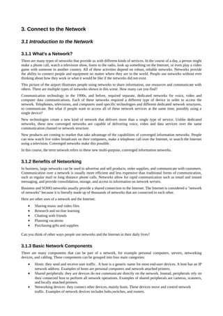
This picture of the airport illustrates people using networks to share information, use resources and communicate with
others. There are multiple types of networks shown in this scene. How many can you find?
Communication technology in the 1990s, and before, required separate, dedicated networks for voice, video and
computer data communications. Each of these networks required a different type of device in order to access the
network. Telephones, televisions, and computers used specific technologies and different dedicated network structures,
to communicate. But what if people want to access all of these network services at the same time, possibly using a
single device?
New technologies create a new kind of network that delivers more than a single type of service. Unlike dedicated
networks, these new converged networks are capable of delivering voice, video and data services over the same
communication channel or network structure.
New products are coming to market that take advantage of the capabilities of converged information networks. People
can now watch live video broadcasts on their computers, make a telephone call over the Internet, or search the Internet
using a television. Converged networks make this possible.
In this course, the term network refers to these new multi-purpose, converged information networks.
3.1.2 Benefits of Networking
In business, large networks can be used to advertise and sell products, order supplies, and communicate with customers.
Communication over a network is usually more efficient and less expensive than traditional forms of communication,
such as regular mail or long distance phone calls. Networks allow for rapid communication such as email and instant
messaging, and provide consolidation, storage, and access to information on network servers.
Business and SOHO networks usually provide a shared connection to the Internet. The Internet is considered a "network
of networks" because it is literally made up of thousands of networks that are connected to each other.
Here are other uses of a network and the Internet:
• Sharing music and video files
• Research and on-line learning
• Chatting with friends
• Planning vacations
• Purchasing gifts and supplies
Can you think of other ways people use networks and the Internet in their daily lives?
3.1.3 Basic Network Components
There are many components that can be part of a network, for example personal computers, servers, networking
devices, and cabling. These components can be grouped into four main categories:
• Hosts: they send and receive user traffic. A host is a generic name for most end-user devices. A host has an IP
network address. Examples of hosts are personal computers and network attached printers.
• Shared peripherals: they are devices do not communicate directly on the network. Instead, peripherals rely on
their connected host to perform all network operations. Examples of shared peripherals are cameras, scanners,
and locally attached printers.
• Networking devices: they connect other devices, mainly hosts. These devices move and control network
traffic. Examples of network devices includes hubs,switches, and routers.
2. • Networking media: it provides connections between hosts and network devices. Network media can be wired,
such as copper and fiber optic or use wireless technologies.
The network components that people are most familiar with are hosts and shared peripherals. Hosts are devices that
send and receive messages directly across the network.
Shared peripherals are not directly connected to the network, but instead are connected to hosts. The host is then
responsible for sharing the peripheral across the network. Hosts have computer software configured to enable people on
the network to use the attached peripheral devices.
The network devices, as well as networking media, are used to interconnect hosts.
Some devices can play more than one role, depending on how they are connected. For example, a printer directly
connected to a host (local printer) is a peripheral. A printer directly connected to a network device and participates
directly in network communications is a host.
3.1.4 Computer Roles in a Network
All computers connected to a network that participate directly in network communication are classified as hosts. Hosts
can send and receive messages on the network. In modern networks, computer hosts can act as a client (computer that
requires services from a server), a server, or both. The software installed on the computer determines which role the
computer plays.
Servers are hosts that have software installed that enable them to provide information, like email or web pages, to other
hosts on the network. Each service requires separate server software. For example, a host requires web server software
in order to provide web services to the network.
Clients are computer hosts that have software installed that enable them to request and display the information obtained
from the server. An example of client software is a web browser, like Internet Explorer.
• Web Client and Server: the web server runs server software and clients use their browser software, such as
Windows Internet Explorer, to access web pages on the server.
• File Client and Server: the file server stores the file, the client devices accesses the file with client software
such as Windows Explorer.
• Email Client and Server: the email server runs server software and clients use their mail client software, such
as Microsoft Outlook, to access email on the server.
A computer with server software can provide services simultaneously to one or many clients.
Additionally, a single computer can run multiple types of server software. In a home or small business, it may be
necessary for one computer to act as a file server, a web server, and an email server.
A single computer can also run multiple types of client software. There must be client software for every service
required. With multiple clients installed, a host can connect to multiple servers at the same time. For example, a user
can check email and view a web page while instant messaging and listening to Internet radio.
3.1.5 Peer-to-Peer Networks
Client and server software usually runs on separate computers, but it is also possible for one computer to carry out both
roles at the same time. In small businesses and homes, many computers function as the servers and clients on the
network. This type of network is called a peer-to-peer network.
The simplest peer-to-peer network consists of two directly connected computers using a wired or wireless connection.
Multiple PCs can also be connected to create a larger peer-to-peer network but this requires a network device, such as a
hub, to interconnect the computers.
The main disadvantage of a peer-to-peer environment is that the performance of a host can be slowed down if it is
acting as both a client and a server at the same time.
In larger businesses, due to the potential for high amounts of network traffic, it is often necessary to have dedicated
servers to support the number of service requests.
The advantages of peer-to-peer networking:
• Easy to set up
• Less complexity
• Lower cost since network devices and dedicates servers may not be required
3. • Can be used for simple tasks such as trasferring files and sharing printers
The disadvantages of peer-to-peer networking:
• No centralized administration
• Not as secure
• Not scalable
• All devices may acts as both clients and servers which can slow their performance
3.1.6 Network Topologies
In a simple network consisting of a few computers, it is easy to visualize how all of the various components connect. As
networks grow, it is more difficult to keep track of the location of each component, and how each is connected to the
network. Wired networks require lots of cabling and network devices to provide connectivity for all network hosts.
When networks are installed, a physical topology map is created to record where each host is located and how it is
connected to the network. The physical topology map also shows where the wiring is installed and the locations of the
networking devices that connect the hosts. Icons are used to represent the actual physical devices within the topology
map. It is very important to maintain and update physical topology maps to aid future installation and troubleshooting
efforts.
In addition to the physical topology map, it is sometimes necessary to also have a logical view of the network topology.
A logical topology map groups hosts by how they use the network, no matter where they are physically located. Host
names, addresses, group information and applications can be recorded on the logical topology map.
The graphics illustrate the difference between logical and physical topology maps.
4. 3.2 Principles of Communication
3.2.1 Source, Channel and Destination
The primary purpose of any network is to provide a method to communicate information. From the very earliest
primitive humans to the most advanced scientists of today, sharing information with others is crucial for human
advancement.
All communication begins with a message, or information, that must be sent from one individual or device to another.
The methods used to send, receive and interpret messages change over time as technology advances.
All communication methods have three elements in common. The first of these elements is the message source, or
sender. Message sources are people, or electronic devices, that need to communicate a message to other individuals or
devices. The second element of communication is the destination, or receiver, of the message. The destination receives
the message and interprets it. A third element, called a channel, provides the pathway over which the message can travel
from source to destination.
3.2.2 Rules of Communication
In any conversation between two people, there are many rules, or protocols, that the two must follow in order for the
message to be successfully delivered and understood. Among the protocols for successful human communication are:
• Identification of sender and receiver
• Agreed-upon medium or channel (face-to-face, telephone, letter, photograph)
• Appropriate communication mode (spoken, written, illustrated, interactive or one-way)
• Common language
• Grammar and sentence structure
• Speed and timing of delivery
Imagine what would happen if no protocols or rules existed to govern how people communicate with each other. Would
you be able to understand them? Are you able to read the paragraph that does not follow commonly accepted protocols?
Protocols are specific to the characteristics of the source, channel and destination of the message. The rules used to
communicate over one medium, like a telephone call, are not necessarily the same as communication using another
medium, such as a letter.
Protocols define the details of how the message is transmitted, and delivered. This includes issues of:
• Message format
• Message size
• Timing
• Encapsulation
• Encoding
• Standard message pattern
Many of the concepts and rules that make human communication reliable and understandable also apply to computer
communication.
3.2.3 Message Encoding
One of the first steps to sending a message is encoding it. Written words, pictures, and spoken languages each use a
unique set of codes, sounds, gestures, and/or symbols to represent the thoughts being shared. Encoding is the process of
converting thoughts into the language, symbols, or sounds, for transmission. Decoding reverses this process in order to
interpret the thought.
Imagine a person watching a sunset and then calling someone else to talk about how beautiful the sunset looks. To
communicate the message, the sender must first convert, or encode, their thoughts and perceptions about the sunset into
5. words. The words are spoken into the telephone using the sounds and inflections of spoken language that convey the
message. On the other end of the telephone line, the person listening to the description, receives and decodes the sounds
in order to visualize the image of the sunset described by the sender.
Encoding also occurs in computer communication. Encoding between hosts must be in an appropriate form for the
medium. Messages sent across the network are first converted into bits by the sending host. Each bit is encoded into a
pattern of sounds, light waves, or electrical impulses depending on the network media over which the bits are
transmitted. The destination host receives and decodes the signals in order to interpret the message.
3.2.4 Message Formatting
When a message is sent from source to destination, it must use a specific format or structure. Message formats depend
on the type of message and the channel that is used to deliver the message.
Letter writing is one of the most common forms of written human communication. For centuries, the agreed format for
personal letters has not changed. In many cultures, a personal letter contains the following elements:
• An identifier of the recipient
• A salutation or greeting
• The message content
• A closing phrase
• An identifier of the sender
In addition to having the correct format, most personal letters must also be enclosed, or encapsulated, in an envelope for
delivery. The envelope has the address of the sender and receiver on it, each located at the proper place on the envelope.
If the destination address and formatting are not correct, the letter is not delivered.
The process of placing one message format (the letter) inside another message format (the envelope) is called
encapsulation. De-encapsulation occurs when the process is reversed by the recipient and the letter is removed from the
envelope.
A letter writer uses an accepted format to ensure that the letter is delivered and understood by the recipient. In the same
way, a message that is sent over a computer network follows specific format rules for it to be delivered and processed.
Just as a letter is encapsulated in an envelope for delivery, so computer messages are encapsulated. Each computer
message is encapsulated in a specific format, called a frame, before it is sent over the network. A frame is logical
grouping of information sent over a trasmission medium as a data link layer unit. Often refers to the header and trailer,
used for synchronization and error control, that surround the user data contained in the unit. A frame acts like an
envelope; it provides the address of the intended destination and the address of the source host.
The format and contents of a frame are determined by the type of message being sent and the channel over which it is
communicated. Messages that are not correctly formatted are not successfully delivered to or processed by the
destination host.
6. 3.2.5 Message Size
Imagine what it would be like to read this course if it all appeared as one long sentence; it would not be easy to read and
comprehend. When people communicate with each other, the messages that they send are usually broken into smaller
parts or sentences. These sentences are limited in size to what the receiving person can process at one time. An
individual conversation may be made up of many smaller sentences to ensure that each part of the message is received
and understood.
Likewise, when a long message is sent from one host to another over a network, it is necessary to break the message
into smaller pieces. The rules that govern the size of the pieces, or frames, communicated across the network are very
strict. They can also be different, depending on the channel used. Frames that are too long or too short are not delivered.
The size restrictions of frames require the source host to break a long message into individual pieces that meet both the
minimum and maximum size requirements. Each piece is encapsulated in a separate frame with the address information,
and is sent over the network. At the receiving host, the messages are de-encapsulated and put back together to be
processed and interpreted.
3.2.6 Message Timing
One factor that affects how well a message is received and understood is timing. People use timing to determine when
to speak, how fast or slow to talk, and how long to wait for a response. These are the rules of engagement.
Access Method
Access Method determines when someone is able to send a message. These timing rules are based on the environment.
For example, you may be able to speak whenever you have something to say. In this environment, a person must wait
until no one else is talking before speaking. If two people talk at the same time, a collision of information occurs and it
is necessary for the two to back off and start again. A collision, in Ethernet, is the result of two or more devices
trasmissing simultaneously. The frame from each device impact and are damaged when they meet on the physical
media. All computer networks require a mechanism to prevent collision or to recover quickly when they occur. These
rules ensure communication is successful. Likewise, it is necessary for computers to define an access method. It is a set
of rules used by LAN hardware to redirect traffic on network. It determines which host or device uses the LAN next.
Hosts on a network need an access method to know when to begin sending messages and how to respond when errors
occur.
Flow Control
Timing also effects how much information can be sent and the speed that it can be delivered. If one person speaks too
quickly, it is difficult for the other person to hear and understand the message. The receiving person must ask the sender
to slow down. In network communication, a sending host can transmit messages at a faster rate than the destination host
can receive and process. Source and destination hosts use flow control to negotiate correct timing for successful
communication.
Response Timeout
If a person asks a question and does not hear a response within an acceptable amount of time, the person assumes that
no answer is coming and reacts accordingly. The person may repeat the question, or may go on with the conversation.
Hosts on the network also have rules that specify how long to wait for responses and what action to take if a response
timeout occurs.
3.2.7 Message Patterns
Sometimes, a person wants to communicate information to a single individual. At other times, the person may need to
send information to a group of people at the same time, or even to all people in the same area. A conversation between
two people is an example of a one-to-one pattern of communication. When a group of recipients need to receive the
same message simultaneously, a one-to-many or one-to-all message pattern is necessary.
There are also times when the sender of a message needs to be sure that the message is delivered successfully to the
destination. In these cases, it is necessary for the recipient to return an acknowledgement to the sender. If no
acknowledgement is required, the message pattern is referred to as unacknowledged.
Hosts on a network use similar message patterns to communicate. A one-to-one message pattern is referred to as a
unicast, meaning that there is only a single destination for the message.
When a host needs to send messages using a one-to-many pattern, it is referred to as a multicast. Multicasting is the
delivery of the same message to a group of host destinations simultaneously. If all hosts on the network need to receive
the message at the same time, a broadcast is used. Broadcasting represents a one-to-all message pattern. Additionally,
hosts have requirements for acknowledged versus unacknowledged messages.
7. 3.2.8 Protocol Use in Communication
All communication, both human and computer, is governed by pre-established rules, or protocols. These protocols are
determined by the characteristics of the source, channel and destination. Based on the source, channel and destination,
the protocols define the details for the issues of message format, message size, timing, encapsulation, encoding and
standard message pattern.
If all hosts on the network need to receive the message at the same time, a broadcast is used. Broadcasting represents a
one-to-all message pattern. Additionally, hosts have requirements for acknowledged versus unacknowledged messages.
3.3 Communicating on a Local Wired Network
3.3.1 Importance of Protocols
Computers, just like humans, use rules, or protocols, in order to communicate.
Protocols are especially important on a local network. In a wired environment, a local network is defined as an area
where all hosts must "speak the same language" or in computer terms "share a common protocol".
If everyone in the same room spoke a different language they would not be able to communicate. Likewise, if devices in
a local network did not use the same protocols they would not be able to communicate.
The most common set of protocols used on local wired networks is Ethernet.
The Ethernet protocol defines many aspects of communication over the local network, including: message format,
message size, timing, encoding, and message patterns.
3.3.2 Standardization of Protocols
In the early days of networking, each vendor used their own, proprietary methods of interconnecting network devices
and networking protocols. Equipment from one vendor could not communicate with equipment from another.
As networks became more widespread, standards were developed that defined rules by which network equipment from
different vendors operated. Standards are beneficial to networking in many ways:
• Facilitate design
• Simplify product development
• Promote competition
• Provide consistent interconnections
• Facilitate training
• Provide more vendor choices for customers
There is no official local networking standard protocol, but over time, one technology, Ethernet, has become more
common than the others. It has become a de facto standard. A de facto standard is a format, language or protocol that
becomes a standard because it is widely used. De jure standard, in contrast, is one that exists because of approval by an
official standard body.
8. The Institute of Electrical and Electronic Engineers, or IEEE (pronounced eye-triple-e), maintains the networking
standards, including Ethernet and wireless standards. IEEE committees are responsible for approving and maintaining
the standards for connections, media requirements and communications protocols. Each technology standard is assigned
a number that refers to the committee that is responsible for approving and maintaining the standard. The committee
responsible for the Ethernet standards is 802.3.
Since the creation of Ethernet in 1973, standards have evolved for specifying faster and more flexible versions of the
technology. This ability for Ethernet to improve over time is one of the main reasons that it has become so popular.
Each version of Ethernet has an associated standard. For example, 802.3 100BASE-T represents the 100 Megabit
Ethernet using twisted pair cable standards. The standard notation translates as:
• 100 is the speed in Mbps
• BASE stands for baseband transmission
• T stands for the type of cable, in this case, twisted pair.
A baseband is a trasmission medium through which digitals signals are sent without complicated frequency shifting. In
general, only one communication channel is available at any given time. Ethernet is an example of a baseband network.
Early versions of Ethernet were relatively slow at 10 Mbps. The latest versions of Ethernet operate at 10 Gigabits per
second and faster. Imagine how much faster these new versions are than the original Ethernet networks.
• 1973 – Ethernet: invented by Dr. Robert Metcalf of Xerox Corp.
• 1980 – DIX Standard: Digital Equipment Corp, Intel and Xerox (DIX) release a standard for 10 Mbps
Ethernet over coaxial cable
• 1983 – IEEE 802.3 10 BASE-5: 10 Mbps Ethernet over thick coaxial cable
• 1985 – IEEE 802.3a 10 BASE-2: 10 Mbps Ethernet over thin coaxial cable
• 1990 – IEEE 802.3i 10 BASE-T: 10 Mbps Ethernet over twisted pair (TP)
• 1993 – IEEE 802.3j 10 BASE-F: 10 Mbps Ethernet over fiber optic
• 1995 – IEEE 802.3u 100 BASE-xx: Fast Ehernet, 100 Mbps Ethernet over twisted pair (TP) and fiber (various
standards)
• 1998 – IEEE 802.3z 1000 BASE-X: Gigabit Ethernet over fiber optic
• 1999 – IEEE 802.3ab 1000 BASE-T: Gigabit Ethernet over twisted pair
• 2002 – IEEE 802.3ae 10G BASE-xx: 10 Gigabit Ethernet over fiber (various standards)
• 2006 – IEEE 802.3an 10G BASE-T: 10 Gigabit Ethernet over twisted pair (TP)
3.3.3 Physical Addressing
All communication requires a way to identify the source and destination. The source and destination in human
communication are represented by names.When a name is called, the person with that name listens to the message and
responds. Other people in the room may hear the message, but they ignore it because it is not addressed to them.
On Ethernet networks, a similar method exists for identifying source and destination hosts. Each host connected to an
Ethernet network is assigned a physical address which serves to identify the host on the network. Every Ethernet
network interface has a physical address assigned to it when it is manufactured. This address is known as the Media
Access Control (MAC) Address. The MAC address identifies each source and destination host on the network.
9. Ethernet networks are cable based, meaning that a copper or fiber optic cable connects hosts and networking devices.
This is the channel used for communications between the hosts.
When a host on an Ethernet network communicates, it sends frames containing its own MAC address as the source and
the MAC address of the intended recipient. Any hosts that receive the frame will decode the frame and read the
destination MAC address. If the destination MAC address matches the address configured on the NIC, it will process
the message and store it for the host application to use. If the destination MAC address does not match the host MAC
address, the NIC will ignore the message.
3.3.4 Ethernet Communication
The Ethernet protocol standards define many aspects of network communication including frame format, frame size,
timing and encoding.
When messages are sent between hosts on an Ethernet network, the hosts format the messages into the frame layout that
is specified by the standards. Frames are also referred to as Protocol Data Units (PDUs).
The format for Ethernet frames specifies the location of the destination and source MAC addresses, and additional
information including:
• Preamble for sequencing and timing
• Start of frame delimiter
• Length and type of frame
• Frame check sequence to detect transmission errors
The size of Ethernet frames is limited to a maximum of 1518 bytes and a minimum size of 64 bytes from the
Destination MAC Address field through the Frame Check Sequence. Frames that do not match these limits are not
processed by the receiving hosts. In addition to the frame formats, sizes and timing, Ethernet standards define how the
bits making up the frames are encoded onto the channel. Bits are transmitted as either electrical impulses over copper
cable or as light impulses over fiber optic cable.
• Preamble: defined pattern of alternating 1 and 0 bits used to synchronize timing
• Start of Frame Delimiter (SFD): marks the end of the timing information and start of the frame
• Destination MAC Address: contains the destination MAC address (receiver). It can be unicast (a specific host),
multicast (a gruop of hosts), or broadcast (all hosts on the local network)
• Source MAC Address: contains the source MAC address (sender). This is the unicast address of the Ethernet
nod that trasmitted the frame
• Lenght/Type: supports two different uses. A type value indicates which protocol will receive the data. The
lenght indicates the number of bytes of data that follow this fields
• Encapsulated Data: contains the packet of information being sent. Ethernet requires each frame to be between
64 amd 1518 bytes
• FCS: contains a 4-byte value that is create by the device that sends data and is recalculated by the destination
device to check for damaged frames
The Preamble and SFD fields are not included in the maxinum/minimum Ethernet frame byte counts
10. 3.3.5 Hierarchical Design of Ethernet Networks
Imagine how difficult communication would be if the only way to send a message to someone was to use the person's
name. If there were no street addresses, cities, towns, or country boundaries, delivering a message to a specific person
across the world would be nearly impossible.
On an Ethernet network, the host MAC address is similar to a person's name. A MAC address indicates the individual
identity of a specific host, but it does not indicate where on the network the host is located. If all hosts on the Internet
(over 400 million of them) were each identified by only their unique MAC address, imagine how difficult it would be to
locate a single one.
Additionally, Ethernet technology generates a large amount of broadcast traffic in order for hosts to communicate.
Broadcasts are sent to all hosts within a single network. Broadcasts consume bandwidth and slow network performance.
What would happen if the millions of hosts attached to the Internet were all in one Ethernet network and were using
broadcasts?
For these two reasons, large Ethernet networks consisting of many hosts are not efficient. It is better to divide larger
networks into smaller, more manageable pieces. One way to divide larger networks is to use a hierarchical design
model.
In networking, hierarchical design is used to group devices into multiple networks that are organized in a layered
approach. It consists of smaller, more manageable groups that allow local traffic to remain local. Only traffic that is
destined for other networks is moved to a higher layer.
A hierarchical, layered design provides increased efficiency, optimization of function, and increased speed. It allows the
network to scale as required because additional local networks can be added without impacting the performance of the
existing ones.
The hierarchical design has three basic layers:
• Access Layer – to provide connections to hosts in a local Ethernet network.
• Distribution Layer – to interconnect the smaller local networks.
• Core Layer – a high-speed connection between distribution layer devices.
With this new hierarchical design, there is a need for a logical addressing scheme that can identify the location of a host.
This is the Internet Protocol (IP) addressing scheme.
3.3.6 Logical Addressing
A person's name usually does not change. A person's address on the other hand, relates to where they live and can
change. On a host, the MAC address does not change; it is physically assigned to the host NIC and is known as the
physical address. The physical address remains the same regardless of where the host is placed on the network.
The IP address is similar to the address of a person. It is known as a logical address because it is assigned logically
based on where the host is located. The IP address, or network address, is assigned to each host by a network
administrator based on the local network.
IP addresses contain two parts. One part identifies the local network. The network portion of the IP address will be the
same for all hosts connected to the same local network. The second part of the IP address identifies the individual host.
Within the same local network, the host portion of the IP address is unique to each host.
11. Both the physical MAC and logical IP addresses are required for a computer to communicate on a hierarchical network,
just like both the name and address of a person are required to send a letter.
3.3.7 Access and Distribution Layers and Devices
IP traffic is managed based on the characteristics and devices associated with each of the three layers: Access,
Distribution and Core. The IP address is used to determine if traffic should remain local or be moved up through the
layers of the hierarchical network.
Access Layer
The Access Layer provides a connection point for end user devices to the network and allows multiple hosts to connect
to other hosts through a network device, usually a hub or switch. Typically, all devices within a single Access Layer will
have the same network portion of the IP address.
If a message is destined for a local host, based on the network portion of the IP address, the message remains local. If it
is destined for a different network, it is passed up to the Distribution Layer. Hubs and switches provide the connection
to the Distribution Layer devices, usually a router.
Distribution Layer
The Distribution Layer provides a connection point for separate networks and controls the flow of information between
the networks. It typically contains more powerful switches than the Access Layer as well as routers for routing between
networks. Routing is a process to find a path to a destination host. It is very complex in large networks because of the
many potential intermediate destinations a packet might traverse before reaching its destination host. Distribution Layer
devices control the type and amount of traffic that flows from the Access Layer to the Core Layer.
Core Layer
The Core Layer is a high-speed backbone layer with redundant (backup) connections. It is responsible for transporting
large amounts of data between multiple end networks. Core Layer devices typically include very powerful, high-speed
switches and routers. The main goal of the Core Layer is to transport data quickly.
Hubs, switches, and routers are discussed in more detail in the next two sections.
3.4 Building the Access Layer of an Ethernet Network
3.4.1 Access Layer
The Access Layer is the most basic level of the network. It is the part of the network in which people gain access to
other hosts and to shared files and printers. The Access Layer is composed of host devices, as well as the first line of
networking devices to which they are attached.
Networking devices enable us to connect many hosts with each other and also provide those hosts access to services
offered over the network. Unlike the simple network consisting of two hosts connected by a single cable, in the Access
Layer, each host is connected to a networking device. This type of connectivity is shown in the graphic.
Within an Ethernet network, each host is able to connect directly to an Access Layer networking device using a point-
12. to-point cable. These cables are manufactured to meet specific Ethernet standards. Each cable is plugged into a host
NIC and then into a port on the networking device. There are several types of networking devices that can be used to
connect hosts at the Access Layer, including Ethernet hubs and switches.
3.4.2 Function of Hubs
A hub is one type of networking device that is installed at the Access Layer of an Ethernet network. Hubs contain
multiple ports that are used to connect hosts to the network. Hubs are simple devices that do not have the necessary
electronics to decode the messages sent between hosts on the network. Hubs cannot determine which host should get
any particular message. A hub simply accepts electronic signals from one port and regenerates (or repeats) the same
message out all of the other ports.
Remember that the NIC on a host accepts messages only addressed to the correct MAC address. Hosts ignore messages
that are not addressed to them. Only the host specified in the destination address of the message processes the message
and responds to the sender.
All of the ports on the Ethernet hub connect to the same channel to send and receive messages. Because all hosts must
share the bandwidth available on that channel, a hub is referred to as a shared-bandwidth device.
Only one message can be sent through an Ethernet hub at a time. It is possible for two or more hosts connected to a hub
to attempt to send a message at the same time. If this happens, the electronic signals that make up the messages collide
with each other at the hub.
A collision causes the messages to become garbled and unreadable by the hosts. A hub does not decode the messages;
therefore it does not detect that the message is garbled and repeats it out all the ports. The area of the network where a
host can receive a garbled message resulting from a collision is known as a collision domain.
In Ethernet, the collision domain is the network area where data that is being trasmitted simultaneously from two or
more computers could collide. Repeaters and hubs propagate collision; LAN switches, bridges and routers do not.
Inside a collision domain, when a host receives a garbled message, it detects that a collision has occurred. Each sending
host waits a short amount of time and then attempts to send, or retransmit, the message again. As the number of hosts
connected to the hub increases, so does the chance of collisions. More collisions cause more retransmissions. Excessive
retransmissions can clog up the network and slow down network traffic. For this reason, it is necessary to limit the size
of a collision domain.
3.4.3 Function of Switches
An Ethernet switch is a device that is used at the Access Layer. Like a hub, a switch connects multiple hosts to the
network. Unlike a hub, a switch can forward a message to a specific host. When a host sends a message to another host
on the switch, the switch accepts and decodes the frames to read the physical (MAC) address portion of the message.
A table on the switch, called a MAC address table, contains a list of all of the active ports and the host MAC addresses
that are attached to them. When a message is sent between hosts, the switch checks to see if the destination MAC
address is in the table. If it is, the switch builds a temporary connection, called a circuit, between the source and
destination ports. This new circuit provides a dedicated channel over which the two hosts can communicate. Other hosts
attached to the switch do not share bandwidth on this channel and do not receive messages that are not addressed to
them. A new circuit is built for every new conversation between hosts. These separate circuits allow many conversations
to take place at the same time, without collisions occurring.
What happens when the switch receives a frame addressed to a new host that is not yet in the MAC address table? If the
destination MAC address is not in the table, the switch does not have the necessary information to create an individual
circuit. When the switch cannot determine where the destination host is located, it uses a process called flooding to
forward the message out to all attached hosts. Each host compares the destination MAC address in the message to its
own MAC address, but only the host with the correct destination address processes the message and responds to the
sender.
How does the MAC address of a new host get into the MAC address table? A switch builds the MAC address table by
examining the source MAC address of each frame that is sent between hosts. When a new host sends a message or
responds to a flooded message, the switch immediately learns its MAC address and the port to which it is connected.
The table is dynamically updated each time a new source MAC address is read by the switch. In this way, a switch
quickly learns the MAC addresses of all attached hosts.
13. Sometimes, it is necessary to connect another networking device, like a hub, to a switch port. This is done to increase
the number of hosts that can be connected to the network. When a hub is connected to a switch port, the switch
associates the MAC addresses of all hosts connected to that hub with the single port on the switch. Occasionally, one
host on the attached hub sends a message to another host attached to the same hub. In this case, the switch receives the
frame and checks the table to see where the destination host is located. If both the source and destination hosts are
located on the same port, the switch discards the message.
When a hub is connected to a switch port, collisions can occur on the hub. The hub forwards to all ports the damaged
messages resulting from a collision. The switch receives the garbled message, but, unlike a hub, a switch does not
forward the damaged messages caused by collisions. As a result, every switch port creates a separate collision domain.
This is a good thing. The fewer hosts contained in a collision domain, the less likely it is that a collision will occur.
3.4.4 Broadcast Messaging
When hosts are connected using either a hub or a switch, a single local network is created. Within the local network it is
often necessary for one host to be able to send messages to all the other hosts at the same time. This can be done using a
message known as a broadcast. Broadcasts are useful when a host needs to find information without knowing exactly
what other host can supply it or when a host wants to provide information to all other hosts in the same network in a
timely manner.
A message can only contain one destination MAC address. So, how is it possible for a host to contact every other host
on the local network without sending out a separate message to each individual MAC?
To solve this problem, broadcast messages are sent to a unique MAC address that is recognized by all hosts.
The broadcast MAC address is hardware address reserved for frames that are intended for all host on a local network
segment. Generallt, a broadcast address is a MAC destination address of all ones. It has the hexadecimal form of
FF:FF:FF:FF:FF:FF. The broadcast MAC address is actually a 48-bit address made up of all ones. Because of their
length, MAC addresses are usually represented in hexadecimal notation. The broadcast MAC address in hexadecimal
notation is FFFF.FFFF.FFFF. Each F in the hexadecimal notation represents four ones in the binary address.
When a host receives a message addressed to the broadcast address, it accepts and processes the message as though the
message was addressed directly to it. When a host sends a broadcast message, hubs and switches forward the message
to every connected host within the same local network. For this reason, a local network is also referred to as a broadcast
domain.
A broadcast domain is formed by devices within a group that receive the same broadcast frame originating from one of
the devices. Broadcast domains are ypically bounded by routers because routers do not forward broadcast frames.
If too many hosts are connected to the same broadcast domain, broadcast traffic can become excessive. The number of
hosts and the amount of network traffic that can be supported on the local network is limited by the capabilities of the
hubs and switches used to connect them. As the network grows and more hosts are added, network traffic, including
broadcast traffic, increases. It is often necessary to divide one local network, or broadcast domain, into multiple
networks to improve performance.
14. 3.4.6 MAC and IP
On a local Ethernet network, a NIC only accepts a frame if the destination address is either the broadcast MAC address,
or else corresponds to the MAC address of the NIC.
Most network applications, however, rely on the logical destination IP address to identify the location of the servers and
clients.
What if a sending host only has the logical IP address of the destination host? How does the sending host determine
what destination MAC address to place within the frame?
The sending host can use an IP protocol called address resolution protocol (ARP) to discover the MAC address of any
host on the same local network.
3.4.7 Address Resolution Protocol (ARP)
ARP uses a three step process to discover and store the MAC address of a host on the local network when only the IP
address of the host is known.
1. The sending host creates and sends a frame addressed to a broadcast MAC address. Contained in the frame is a
message with the IP address of the intended destination host.
2. Each host on the network receives the broadcast frame and compares the IP address inside the message with its
configured IP address. The host with the matching IP address sends its MAC address back to the original
sending host.
3. The sending host receives the message and stores the MAC address and IP address information in a table called
an ARP table.
Once the sending host has the MAC address of the destination host in its ARP table, it can send frames directly to the
destination without doing an ARP request.
15. 3.5 Building the Distribution Layer of Network
3.5 Distribution Layer
As networks grow, it is often necessary to divide one local network into multiple Access Layer networks. There are
many ways to divide networks based on different criteria, including:
• Physical location
• Logical function
• Security requirements
• Application requirements
The Distribution Layer connects these independent local networks and controls the traffic flowing between them. It is
responsible for ensuring that traffic between hosts on the local network stays local. Only traffic that is destined for other
networks is passed on. The Distribution Layer can also filter incoming and outgoing traffic for security and traffic
management.
Networking devices that make up the Distribution Layer are designed to interconnect networks, not individual hosts.
Individual hosts are connected to the network via Access Layer devices, such as hubs and switches. The Access Layer
devices are connected to each other via the Distribution Layer device, such as routers.
Functions of the routers in distribution layer:
• Broadcast Containment: they can limit broadcast to the local network where they need to be heard. Although
broadcast are necessary, too many hosts connected on the same local network can generate excessive broadcast
traffic and slow down the network.
• Security: they can separate and protect certain groups of computers where confidential information resides.
Routers can also hide the addresses of internal computers from the outside world to help prevent attacks, and
control who can get into or out of the local network.
• Locations: they can be used to interconnect local networks at various locations of an organization that are
geographically separated.
• Logical Grouping: they can be used to logically group users, such as departments within a company, who
have common need or for access to resources.
16. 3.5.2 Function of Routers
A router is a networking device that connects a local network to other local networks. At the Distribution Layer of the
network, routers direct traffic and perform other functions critical to efficient network operation. Routers, like switches,
are able to decode and read the messages that are sent to them. Unlike switches, which only decode (unencapsulate) the
frame containing the MAC address information, routers decode the packet that is encapsulated within the frame.
A packet is a logical grouping of information which includes a header that contains control information and usually user
data. Packets are most oftern used to refer to network layer units of data.
The packet format contains the IP addresses of the destination and source hosts, as well as the message data being sent
between them. The router reads the network portion of the destination IP address and uses it to find which one of the
attached networks is the best way to forward the message to the destination.
Anytime the network portion of the IP addresses of the source and destination hosts do not match, a router must be used
to forward the message. If a host located on network 1.1.1.0 needs to send a message to a host on network 5.5.5.0, the
host will forward the message to the router. The router receives the message and unencapsulates it to read the
destination IP address. It then determines where to forward the message. It re-encapsulates the packet back into a frame,
and forwards the frame on to its destination.
How does the router determine what path to send the message to get to the destination network?
Each port, or interface, on a router connects to a different local network. Every router contains a table of all locally-
connected networks and the interfaces that connect to them. These routing tables can also contain information about the
routes, or paths, that the router uses to reach other remote networks that are not locally attached.
When a router receives a frame, it decodes the frame to get to the packet containing the destination IP address. It
matches the address of the destination to all of the networks that are contained in the routing table. If the destination
network address is in the table, the router encapsulates the packet in a new frame in order to send it out. It forwards the
new frame out of the interface associated with the path, to the destination network. The process of forwarding the
packets toward their destination network is called routing.
Router interfaces do not forward messages that are addressed to the local network broadcast IP address. As a result,
local network broadcasts are not sent across routers to other local networks.
3.5.3 Default Gateway
The method that a host uses to send messages to a destination on a remote network differs from the way a host sends
messages on the same local network. When a host needs to send a message to another host located on the same network,
it will forward the message directly. A host will use ARP to discover the MAC address of the destination host. It
includes the destination IP address within the packet and encapsulates the packet into a frame containing the MAC
address of the destination and forwards it out.
On the other hand, when a host needs to send a message to a remote network, it must use the router. The host includes
the IP address of the destination host within the packet just like before. However, when it encapsulates the packet into a
frame, it uses the MAC address of the router as the destination for the frame. In this way, the router will receive and
accept the frame based on the MAC address.
How does the source host determine the MAC address of the router? A host is given the IP address of the router through
the default gateway address configured in its TCP/IP settings. A default gateway is the route taken so that a computer on
one segment can communicate with a computer on another segment. The default gateway address is the address of the
router interface connected to the same local network as the source host. All hosts on the local network use the default
gateway address to send messages to the router. Once the host knows the default gateway IP address, it can use ARP to
determine the MAC address. The MAC address of the router is then placed in the frame, destined for another network.
17. It is important that the correct default gateway be configured on each host on the local network. If no default gateway is
configured in the host TCP/IP settings, or if the wrong default gateway is specified, messages addressed to hosts on
remote networks cannot be delivered.
3.5.4 Tables Maintained by Routers
Routers move information between local and remote networks. To do this, routers must use both ARP and routing tables
to store information. Routing tables are not concerned with the addresses of individual hosts. Routing tables contain the
addresses of networks and the best path to reach those networks. Entries can be made to the routing table in two ways:
dynamically updated by information received from other routers in the network, or manually entered by a network
administrator. Routers use the routing tables to determine which interface to use to forward a message to its intended
destination.
If the router cannot determine where to forward a message, it will drop it. Network administrators configure a routing
table with a default route to keep a packet from being dropped because the path to the destination network is not in the
routing table. A default route is the interface through which the router forwards a packet containing an unknown
destination IP network address. This default route usually connects to another router that can forward the packet
towards its final destination network.
A router forwards a frame to one of two places: a directly connected network containing the actual destination host, or
to another router on the path to reach the destination host. When a router encapsulates the frame to forward it out of an
Ethernet interface, it must include a destination MAC address.
This is the MAC address of the actual destination host, if the destination host is part of a network locally connected to
the router. If the router must forward the packet to another router, it will use the MAC address of the connected router.
Routers obtain these MAC addresses from ARP tables.
Each router interface is part of the local network to which it is attached and maintains its own ARP table for that
network. The ARP tables contain the MAC addresses and IP addresses of all of the individual hosts on that network.
18. 3.5.5 Local Area Network (LAN)
The term Local Area Network (LAN) refers to a local network, or a group of interconnected local networks that are
under the same administrative control. In the early days of networking, LANs were defined as small networks that
existed in a single physical location. While LANs can be a single local network installed in a home or small office, the
definition of LAN has evolved to include interconnected local networks consisting of many hundreds of hosts, installed
in multiple buildings and locations.
The important thing to remember is that all of the local networks within a LAN are under one administrative control.
Other common characteristics of LANs are that they typically use Ethernet or wireless protocols, and they support high
data rates.
The term Intranet is often used to refer to a private LAN that belongs to an organization, and is designed to be
accessible only by the organization's members, employees, or others with authorization.
3.5.6 Adding Hosts to Local and Remote Networks
Within a LAN, it is possible to place all hosts on a single local network or divide them up between multiple networks
connected by a Distribution Layer. The answer depends on desired results. Placing all hosts on a single local network
allows them to be seen by all other hosts. This is because there is one broadcast domain and hosts use ARP to find each
other.
In a simple network design it may be beneficial to keep all hosts within a single local network. However, as networks
grow in size, increased traffic will decrease network performance and speed. In this case, it may be beneficial to move
some hosts onto a remote network.
Placing additional hosts on a remote network will decrease the impact of traffic demands. However, hosts on one
network will not be able to communicate with hosts on the other without the use of routing. Routers increase the
complexity of the network configuration and can introduce latency, or time delay, on packets sent from one local
network to the other.
Placing All Hosts in One Local Network Segment
Advantages:
• Appropriate for simpler networks
• Less complexity and lower network cost
• Allows devices to be “seen” by other devices
19. • Faster data tranfer – more direct communication
• Ease of device access
Disadvantages:
• All hosts are in one broadcast domain which causes more traffic on the segment and may slow network
performance
Placing Hosts in Remote Network Segments
Advantages:
• More appropriate for larger, more complex networks
• Splits up broadcast domains and decreases traffic
• Can improve performance on each segments
• Can provide increased securiy
• Can improve network organization
Disadvantages:
• Requires the use of routing (distribution layer)
• Route can slow traffic between segments
• More complexity and expense (requires router)
3.6 Plan and Connect a Local Network
3.6.1 Plan and Document an Ethernet Network
Most local networks are based on Ethernet technology. This technology is both fast and efficient when used in a
properly designed and constructed network. The key to installing a good network is planning before the network is
actually built.
A network plan starts with the gathering of information about how the network will be used. This information includes:
• The number and type of hosts to be connected to network
• The applications to be used
• Sharing and Internet connectivity requirements
• Security and privacy considerations
20. • Reliability and uptime expectations
• Connectivity requirements including, wired and wireless
Information Gathering
Number and type of hosts – Where are the end users located? What type of hardware are they using? Where are the
servers, printers and other network devices located?
Applications – What type of applications are running on the network?
Data and devices to be shared – Who requires access to which files and network resources such as printers?
Bandwidth requirements (speed) – What is an acceptable speed for the end users? Do all users require the same
throughput? What affect will the applications have on the throughput?
Security – Is the data being moved on the network of a personal or sensitive nature? Could unauthorized access to this
information cause harm to anyone?
Reliability – How important is the network? Does it need to be available 100% of the time (this is known as uptime)?
How much down time can be tolerated?
Requirement for wireless – Do any or all of the end users require wireless connectivity?
There are many considerations that must be taken into account when planning for a network installation. The logical
and physical topology maps of the network need to be designed and documented before the networking equipment is
purchased and the hosts are connected. Some things to consider include:
Physical environment where the network will be installed:
• Temperature control: all devices have specific ranges of temperature and humidity requirements for proper
operation
• Availability and placement of power outlets
Physical configuration of the network:
• Physical location of devices such as routers, switches, and hosts
• How all devices are interconnected
• Location and length of all cable runs
• Hardware configuration of end devices such as hosts and servers
Logical configuration of the network:
• Location and size of broadcast and collision domains
• IP addressing scheme
• Naming scheme
• Sharing configuration
• Permissions
21. 3.6.2 Prototypes
Once the network requirements are documented, and the physical and logical topology maps created, the next step in
the implementation process is to test the network design. One of the ways to test a network design is to create a working
model, or prototype, of the network.
Prototyping is essential as networks grow in size and complexity. A prototype allows a network administrator to test
whether or not the planned network will operate as expected, before money is spent on equipment and installation.
Documentation should be maintained on all aspects of the prototyping process.
Prototyping is the process of putting togrther a working model to test design aspects, demonstrate features, and gather
feedback. Prototyping can help reduce project risk and cost.
Various tools and techniques are available for network prototyping; this includes real equipment set up in a lab
environment, modeling and simulation tools. Packet Tracer is one example of a simulation and modeling tool that can
be used for prototyping.
22. 3.6.3 Multi-fuction Device
Most home and small business networks do not require high-volume devices used in large business environments;
smaller scale devices may well be suitable. However, the same functionality of routing and switching is required. This
need has led to the development of products that have the functionality of multiple network devices, such as a router
with switching functionality and a wireless access point. An access point is wireless LAN trasmitter/receiver that acts as
a connection between wireless clients and wired networks. For the purpose of this course, multi-function devices will be
referred to as integrated routers. Integrated routers can range from small devices designed for home office and small
business applications to more powerful devices that can support enterprise branch offices.
An integrated router is like having several different devices connected together. For example, the connection between
the switch and the router still occurs, but it occurs internally. When a broadcast is received on a switch port, the
integrated router forwards the broadcast to all ports including the internal router connection. The router portion of the
integrated router stops the broadcasts from going any further.
There are low-cost multi-function devices available for home and small business networks that offer integrated routing,
switching, wireless and security capabilities. An example of this type of integrated router is a Linksys wireless router.
They are simple in design and do not typically have separate components. In the event of a failure, it is not possible to
replace any single failed component. As such, they create a single point of failure, and are not optimized for any one
function.
Another example of an integrated router is the Cisco integrated services router or ISR. The Cisco ISR product family
offers a wide range of products, including those designed for small office and home office environments as well as
those designed for larger networks. Many of the ISRs offer modularity and have separate components for each function,
such as a switch component and a router component. This enables individual components to be added, replaced and
upgraded as necessary.
3.6.4 Connecting the Linksys Router
Linksys Model WRT300N2
Front View
The Linksys is a simplified, low-cost device that carries out the functionality of multiple network devices (switch,
router, wireless access point). Light emitting diodes (LED) indicate the connection status of each port.
LED Descriprions:
• Power LED – indicates the presence of power to the device; solid green LED
• WLAN LED – indicates status of wireless connections
• 1-4 LEDs – indicates status of the Internet connection
• Internet LED – indicates status of the Internet connection
Color Status of LEDs:
• Green – indicates a connection is made with an end device
• Red or Yellow – usually indicates a problem with the connection
• Blinking – indicates activity on the port
23. Rear View
When connecting a local network using a multifunction device it is important that all local devices are connected to the
switch ports.
1. Internet Port: a single port that is connected to the router portion of the multifunction device. Tgis is used to connect
the device to another network such as the Internet. The router portion of a multifunction device maintains routing tables.
There is an internal connection from the routing portion of the multifuncion device to the switch portion. The Internet
port is connected to a different network than the Ethernet ports.
2. Ethernet Ports: multile ports that are connected to the internal switch portion of the multifunction device. These are
usually labeled “Ethernet”. All devices connected to the switch ports are on the same local network. There is also an
internal connection form the switch port to the router port (Internet Port).
All devices connected to the switch ports should be in the same broadcast domain. This means that all devices must
have an IP address from the same network. Any device that has a different network portion within the IP address will
not be able to communicate.
Additionally, Microsoft Windows makes use of computer names to identify other devices on the network. It is important
to use these names as well as all IP address information in the planning and documentation to assist in future
troubleshooting.
To display the current IP configuration in Microsoft Windows, use the command ipconfig. More detailed information,
including host name, is available with the ipconfig /all. Document all information from the connection and
configuration process.
Once hosts are communicating across the network, it is important to document network performance. This is known as
determining the baseline for the network, and is used as an indication of normal operations. When comparing future
network performance with the baseline, it can indicate if possible issues exist.
Baseline is a quantitative expression of planned costs, schedules, and technical requirements for a defined project. A
baseline is established to describe the “normal” status of network or computer system performance. The status can then
be compared with the baseline at any point to resume the variation from the “normal” operation condition.
24. 3.6.5 Sharing Resources
One of the most common purposes of networking is to share resources such as files and printers. Windows XP enables
remote users to access a local machine and its resources through Sharing. It is important to consider security issues, and
to assign specific permissions to shared resources.
By default, Windows XP uses a process known as Simple File Sharing. With Simple File Sharing, specific users and
groups cannot be prevented from accessing shared files.
Simple File Sharing can be disabled so that more specific security access levels can be assigned. When this is done, the
following permissions are available to assign to resources:
• Full Control
• Modify
• Read & Execute
• List Folder Contents
• Read
• Write
When a user accesses a file on a remote device, Windows Explorer allows the user to map a drive to a remote folder or
resource. This maps a specific drive letter, for example M:, to the remote resource. This enables the user to treat the
resource as though it was locally connected.