
Empfohlen
Weitere ähnliche Inhalte
Was ist angesagt?
Was ist angesagt? (20)
Ähnlich wie Unsymmetrical bending
Ähnlich wie Unsymmetrical bending (20)
Kürzlich hochgeladen
Kürzlich hochgeladen (20)
Unsymmetrical bending
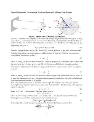
- 1. General Solutions for Unsymmetrical Bending of Beams with Arbitrary Cross Sections y M My y dA z θ α yθ z x z Mz P P Figure 1 A Beam with An Arbitrary Cross Section Consider a cantilever beam subjected to an end force P acting in the plane inclined at an angle θ to the y-‐‑ axis as shown. The bending moment M, produced by the force P, is oriented in the direction making an angle θ to the z-‐‑axis as shown. The components of M in the y and z-‐‑directions, denoted by M y and M z , respectively, are given by My = M sinθ Mz = M cosθ (a) Consider the special case where θ = 90 . From (a) we have My = M and Mz = 0 , then the beam would deflect in the xz plane, and the neutral axis would coincide with the y-‐‑aixs. With the “cross sections remain plane” assumption, we have z ε x = κ z z = (b) ρz where κ z and ρ z are the curvature and radius of curvature, respectively, of the beam in the xz plane. On the other hand, if θ = 0 , then Mz = M and My = 0 , the beam would deflect in the xy plane and the neutral axis would coincide with the z-‐‑aixs. Again, with the “cross sections remain plane” assumption, we have y ε x = −κ y y = − (c) ρy where κ y and ρ y are the curvature and radius of curvature, respectively, of the beam in the yz plane. It is noted that the negative sign in (c) indicates that a line element located above the z-‐‑axis would be under compression when a positive M z is applied. Now consider the general cases in which the value of angle θ is arbitrary. Since the “cross sections remain plane” assumption is still valid, we can express the strain in the x direction in the following linear equation in y and z: ε x = aʹ′ + bʹ′y + cʹ′z (d) where aʹ′ , bʹ′ , and cʹ′ are constants. The stress is then given by σ x = Eε x = a + by + cz (e) where E is the Young’s modulus and a = Eaʹ′ , b = Ebʹ′ , and c = Ec ʹ′ . For a beam subjected to pure bending, the stress resultant over the cross section must vanish, i.e., ∫ σ x dA = a ∫ dA + b∫ ydA + c ∫ zdA = 0 (f) If the origin of the coordinate system coincides with the centroid of the cross section, then y= ∫ ydA = 0, z= ∫ zdA = 0 ∫ dA ∫ dA 1
- 2. Consequently, a = 0 and (e) becomes σ x = by + cz (g) The resultant moments on the cross section are given by M y = ∫ σ x zdA = b ∫ yzdA + c ∫ z 2 dA = bI yz + cI y (h) M z = − ∫ σ x ydA = −b ∫ y 2 dA − c ∫ yzdA = −bI z − cI yz (i) where I y = ∫ z 2 dA , I z = ∫ y 2 dA , I yz = ∫ yzdA are the moments of inertia of the cross section. Solving (h) and (i) simultaneously yields M z I y + M y I yz M y I z + M z I yz b=− 2 , c= 2 (j) I y I z − I yz I y I z − I yz Substituting (j) into (g) gives M z I y + M y I yz M y I z + M z I yz σx = − 2 y+ 2 z (k) IyIz − I yz I y I z − I yz The neutral axis, by definition, is the line along which stress vanishes. Thus, by setting σ x = 0 in (k), we have y M y I z + M z I yz I yz + I z tan θ I z + I yz cot θ tan α = = = = (l) z M z I y + M y I yz I y + I yz tan θ I yz + I y cot θ in which α (see Fig. 1) is the angle measured clockwise from the z-‐‑axis to the neutral axis, and My M tan θ = , or cotθ = z (m) Mz My Combining (k) and (m) and eliminating M y , we obtain the following simplified equation in terms of M z and angle α for calculating the stresses: Mz (y − z tanα ) σx = − (n) I z − I yz tan α If the y-‐‑ and z-‐‑axes coincide with the principal axes, then I yz = 0 and (l) reduces to Iz tan α = tan θ Iy which is the same as (6-‐‑19) in the textbook. Furthermore, if θ = 0 (i.e., Mz = M and My = 0 ), then α = 0 and (n) becomes Mz y σx = − Iz Example: A 5.0 m long simply-‐‑supported beam is subjected to a force P = 4 kN at a point that is 2.0 m away from the far end, as shown in the figure. The dimensions of the L-‐‑shaped cross section are shown in the figure. If the force P is applied in an inclined plane making a 10° angle with the y-‐‑axis, determine the locations and magnitudes of the maximum tensile and compressive stresses in the beam. Solution: (a) Locate the centroid of the cross section (in terms of distances y 0 and z0 measured from point A): (120 × 10)(60) + (70 × 10)(5 ) y0 = = 39.74 mm (120 × 10) + (70 × 10) (120 × 10)(5) + (70 × 10)(45) z0 = = 19.74 mm (120 × 10) + (70 × 10) 2
- 3. P y 10 B 10 mm 2 m P 120 mm α z M 10 10 mm 3 m y0 A z0 80 mm Figure 2 Umsymmetric Bending of A Simply-Supported Beam (b) Determine the moments of inertia: (120)(10)3 (10)(70)3 Iy = + (120)(10)(19.74 − 5)2 + + (10)(70)(45 − 19.74 )2 = 1.003 × 106 mm 4 12 12 (10)(120)3 (70)(10)3 Iz = + (10)(120)(60 − 39.74 )2 + + (70)(10)(39.74 − 5)2 = 2.783 × 106 mm 4 12 12 I yz = (10)(1120)(60 − 39.74 )(19.74 − 5) + (70)(10)(5 − 39.74)(19.74 − 45) = 0.973 × 106 mm 4 (c) Determine the neutral axis: Since θ = −10 (i.e., positive θ measured clockwise from the z axis), we have, from (l), I yz + I z tan θ 0.973 × 10 6 + 2.783 × 10 6 × tan − 10( ) tan α = = = 0.580 I y + I yz tan θ 1.003 × 10 6 + 0.973 × 10 6 × tan − 10( ) The neutral axis thus is oriented at the angle α = tan−1 (0.580) = 0.526 rad = 30.12 (d) Determine the maximum stresses in the beam: The maximum bending moment along the beam occurs at the point where the load P is applied, i.e., Pab (4.0 )(2.0)(3.0) Mmax = = = 4.8 kN ⋅ m = 4.8 × 10⁶ N ⋅ mm L 5.0 where L = 5.0 m , a = 2.0 m , and b = 3.0 m . The y and z components of this moment are My = Mmax sin θ = −0.834 × 10⁶ N ⋅ mm Mz = Mmax cos θ = 4.727 × 10⁶ N ⋅ mm From Fig.2 it is easy to see that the two locations denoted by A and B are the farthest from the neutral axis, hence would experience the highest tensile or compressive stresses. The y and z coordinates of those two points are A(−39.74 , 19.74 ) and B(80.26 , 9.74 ) , respectively. The maximum tensile stress, occurs at point A, is given by 3
- 4. M z (y − z tan α ) σx = − I z − I yz tan α =− (4.727 × 10 )[− 39.74 − (19.74)tan(30.12 )] 6 2.783 × 10 − (0.973 × 10 )tan(30.12 ) 6 6 N = 109.0 × 106 = 109.0 MPa mm 2 The maximum compressive stress, occurs at point B, is given by M (y − z tan α ) σx = − z I z − I yz tan α =− (4.727 × 10 )[80.26 − (9.74)tan(30.12 )] 6 2.783 × 10 − (0.973 × 10 )tan(30.12 ) 6 6 N = −159.0 × 106 = −159.0 MPa mm 2 (e) Solve the same problem by using the method outlined in Section 6-‐‑5 of the textbook: The principal axes are denoted as Y and Z, respectively, in Fig.3. The directions of the principal axes and the principal moments of inertia of the cross section can be obtained by using (A-‐‑11) and (A-‐‑12) in the textbook. Let β be the angle between the principal axis and y-‐‑axis (see Fig.2), then from (A-‐‑11) 2 I yz 2(0.973 × 10⁶ ) tan 2θ p = tan 2 β = − =− = 1.093 Iy − Iz 1.003 × 10 6 − 2.783 × 10 6 and 1 β = tan −1 (1.093) = 23.8 2 The principal moments of inertia can be obtained by substituting the value of β in (A-‐‑10), or using (A-‐‑12): P y Y 10 B β π −β 2 ψ α z M 10 β Z A Figure 3 Neutral Axis and Principal Axes 4
- 5. 2 Iy + Iz ⎛ I y − I z ⎞ 2 6 4 6 4 I max,min = ⎜ 2 ⎟ + I yz = 3.212 × 10 mm , 0.574 × 10 mm , ± ⎜ ⎟ 2 ⎝ ⎠ Thus, IY = 0.574 × 106 mm 4 I Z = 3.212 × 106 mm 4 The components of M in the Y and Z directions, respectively, are now given by MY = M sin(β − 10 ) = 1.143 × 10⁶ N ⋅ mm MZ = M cos(β − 10 ) = 4.662 × 10⁶ N ⋅ mm The angle ψ , which determines the orientation of neutral axis and is measured clockwise from the Z-‐‑ axis as shown in Fig.3, is given by Y M I I ( tan ψ = = Y Z = Z tan β − 10 = 1.374 Z MZ I Y I Y ) from which ψ = tan −1 (1.374 ) = 53.9 It can be seen from Fig.3 that α = ψ − β = 30.1 which matches the value obtained previously. With respect to the principal axes, the stresses are given by M Z M Y σ x = Y − Z IY IZ At point A, the coordinates are YA = y A cos β + z A sin β = −28.4 mm Z A = − y A sin β + z A cos β = 34.1 mm and the stress is given by MY Z MZY (1.143 × 10 3 )(34.1) (4.662 × 10 3 )(− 28.4 ) σx = − = − = 109.0 MPa IY IZ 0.574 × 10⁶ 3.212 × 10⁶ At point B, the coordinates are YB = y B cos β + zB sin β = 77.4 mm ZB = − y B sin β + zB cos β = −23.5 mm and the stress is given by M Z M Y (1.143 × 10 3 )(− 23.5 ) (4.662 × 10 3 )(77.4 ) σx = Y − Z = − = −159.0 MPa IY IZ 0.574 × 10⁶ 3.212 × 10⁶ 5