Weitere ähnliche Inhalte
Ähnlich wie Ac theory module08
Ähnlich wie Ac theory module08 (20)
Ac theory module08
- 1. Module
AC Theory
8
Filters & Wave Shaping
Introduction to Passive Filters
Passive Filters & Passive filters, often consisting of only two or three
Wave Shaping components, are used to reduce (ATTENUATE) the
amplitude of signals. They are frequency selective, so
they can reduce the signal amplitude at some
frequencies, without affecting others. Filter circuits are
What you'll learn in Module 8. named to show which frequencies they affect.
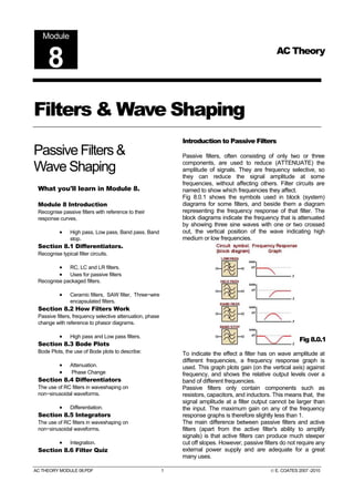
Fig 8.0.1 shows the symbols used in block (system)
Module 8 Introduction diagrams for some filters, and beside them a diagram
Recognise passive filters with reference to their representing the frequency response of that filter. The
response curves. block diagrams indicate the frequency that is attenuated
by showing three sine waves with one or two crossed
• High pass, Low pass, Band pass, Band out, the vertical position of the wave indicating high
stop. medium or low frequencies.
Section 8.1 Differentiators.
Recognise typical filter circuits.
• RC, LC and LR filters.
• Uses for passive filters
Recognise packaged filters.
• Ceramic filters, SAW filter, Three−wire
encapsulated filters.
Section 8.2 How Filters Work
Passive filters, frequency selective attenuation, phase
change with reference to phasor diagrams.
• High pass and Low pass filters.
Fig 8.0.1
Section 8.3 Bode Plots
Bode Plots, the use of Bode plots to describe: To indicate the effect a filter has on wave amplitude at
different frequencies, a frequency response graph is
• Attenuation. used. This graph plots gain (on the vertical axis) against
• Phase Change frequency, and shows the relative output levels over a
Section 8.4 Differentiators band of different frequencies.
The use of RC filters in waveshaping on Passive filters only contain components such as
non−sinusoidal waveforms. resistors, capacitors, and inductors. This means that, the
signal amplitude at a filter output cannot be larger than
• Differentiation. the input. The maximum gain on any of the frequency
Section 8.5 Integrators response graphs is therefore slightly less than 1.
The use of RC filters in waveshaping on The main difference between passive filters and active
non−sinusoidal waveforms. filters (apart from the active filter's ability to amplify
signals) is that active filters can produce much steeper
• Integration. cut off slopes. However, passive filters do not require any
Section 8.6 Filter Quiz external power supply and are adequate for a great
many uses.
AC THEORY MODULE 08.PDF 1 © E. COATES 2007 -2010
- 2. www.learnabout-electronics.org Filters & Wave shaping
Module 8.1 Passive Filters
Uses for passive filters.
Filters are widely used to give circuits such as amplifiers, oscillators and power supply circuits the
required frequency characteristic. Some examples are given below. They use combinations of R, L
and C
As described in Module 6, Inductors and Capacitors react to changes in frequency in opposite ways.
Looking at the circuits for low pass filters, both the LR and CR combinations shown have a similar
effect, but notice how the positions of L and C change place compared with R to achieve the same
result. The reasons for this, and how these circuits work will be explained in Section 8.2 of this module.
Low pass filters.
Low pass filters are used to remove or
attenuate the higher frequencies in circuits
such as audio amplifiers; they give the required
frequency response to the amplifier circuit. The
frequency at which the low pass filter starts to
reduce the amplitude of a signal can be made
adjustable. This technique can be used in an
audio amplifier as a "TONE" or "TREBLE CUT" control. LR low pass filters and CR high pass filters
are also used in speaker systems to route appropriate bands of frequencies to different designs of
speakers (i.e. ´ Woofers´ for low frequency, and ´Tweeters´ for high frequency reproduction). In this
application the combination of high and low pass filters is called a "crossover filter".
Both CR and LC Low pass filters that remove practically ALL frequencies above just a few Hz are
used in power supply circuits, where only DC (zero Hz) is required at the output.
High pass filters.
High pass filters are used to remove or
attenuate the lower frequencies in amplifiers,
especially audio amplifiers where it may be
called a "BASS CUT" circuit. In some cases
this also may be made adjustable.
Band pass filters.
Band pass filters allow only a required band of frequencies to pass,
while rejecting signals at all frequencies above and below this band.
This particular design is called a T filter because of the way the
components are drawn in a schematic diagram. The T filter consists of
three elements, two series connected LC circuits between input and
output, which form a low impedance path to signals of the required
frequency, but have a high impedance to all other frequencies.
Additionally, a parallel LC circuit is connected between the signal path (at the junction of the two series
circuits) and ground to form a high impedance at the required frequency, and a low impedance at all
others. Because this basic design forms only one stage of filtering it is also called a ´first order´ filter.
Although it can have a reasonably narrow pass band, if sharper cut off is required, a second filter may
be added at the output of the first filter, to form a ´second order´ filter.
AC THEORY MODULE 08.PDF 2 © E. COATES 2007 -2011
- 3. www.learnabout-electronics.org Filters & Wave shaping
Band stop filters.
These filters have the opposite effect to band pass filters,
there are two parallel LC circuits in the signal path to form a
high impedance at the unwanted signal frequency, and a
series circuit forming a low impedance path to ground at the
same frequency, to add to the rejection. Band stop filters
may be found (often in combination with band pass filters)
in the intermediate frequency (IF) amplifiers of older radio
and TV receivers, where they help produce the frequency response curves of quite complex shapes
needed for the correct reception of both sound and picture signals. Combinations of band stop and
band pass filters, as well as tuned transformers in these circuits, require careful frequency adjustment.
I.F. Transformers.
These are small transformers, used in radio and TV equipment to pass
a band of radio frequencies from one stage of the intermediate
frequency (IF) amplifiers, to the next. They have an adjustable core of
compressed iron dust (Ferrite). The core is screwed into, or out of the
windings forming a variable inductor.
This variable inductor, together with a fixed capacitor ´tunes´ the
transformer to the correct frequency. In older TV receivers a number of
individually tuned IF transformers and adjustable filter circuits were
used to obtain a special shape of pass band in a chain of amplifiers
that amplify sound and vision signals. This practice has largely been
replaced in modern receivers by packaged filters and SAW Filters.
Packaged Filters.
There are thousands of filters listed in component catalogues, some using combinations of L C and R,
but many making use of ceramic and crystal piezo-electric materials. These produce an a.c. electric
voltage when they are mechanically vibrated, and they also vibrate when an a.c. voltage is applied to
them. They are manufactured to resonate (vibrate) only at one particular, and very accurately
controlled frequency and are used in applications such as band pass and band stop filters where a
very narrow pass band is required. Similar designs (crystal resonators) are used in oscillators to
control the frequency they produce, with great accuracy. One packaged filter in TV receivers can
replace several conventional IF transformers and LC filters. Because they require no adjustment, the
manufacture of RF (radio frequency) products such as radio, TV, mobile phones etc. is simplified and
consequently lower in price. Sometimes however, packaged filters will be found to have an
accompanying LC filter to reject frequencies at harmonics of their design frequency, which ceramic
and crystal filters may fail to eliminate.
TV SAW Filter
The illustration (right) shows a Surface Acoustic Wave (SAW) IF
(intermediate frequency) filter for PAL TV. SAW filters can be
manufactured to either a very narrow pass band, or a very wide band
with a complex (pass and stop) response to several different
frequencies. They can produce several different signals of specific
amplitudes at their output. Special TV types replace several LC tuned
filters in modern TVs with a single filter. They work by creating acoustic
waves on the surface of a crystal or tantalum substrate, produced by a
pattern of electrodes arranged as parallel lines on the surface of the chip. The waves created by one
set of transducers are sensed by another set of transducers designed to accept certain wavelengths
and reject others. Saw filters are produced for many different products and have response curves
tailored to the requirements of specific types of product.
AC THEORY MODULE 08.PDF 3 © E. COATES 2007 -2011
- 4. www.learnabout-electronics.org Filters & Wave shaping
Ceramic Filters
Ceramic filters are available in
a number of specific
frequencies, and use a tiny
block of piezo electric ceramic
material that will mechanically
vibrate when an AC signal of
the correct frequency is applied
to an input transducer attached
to the block. This vibration is
converted back into an electrical signal by an output transducer, so only signals of a limited range
around the natural resonating frequency of the piezo electric block will pass through the filter. Ceramic
filters tend to be cheaper, more robust and more accurate than traditional LC filters for applications at
radio frequencies. They are supplied in different forms including surface mount types, and the
encapsulated three-pin package shown here.
AC THEORY MODULE 08.PDF 4 © E. COATES 2007 -2011
- 5. www.learnabout-electronics.org Filters & Wave shaping
Module 8.2 How Filters Work.
CR Filter Operation.
Figs 8.2.1 and 8.2.2 show two common methods of using C and R together to achieve alterations in
AC signals. These CR combinations are used for many purposes in a wide variety of circuits. This
section describes their effects when used as filters with sine wave signals of varying frequencies. The
same circuits are also used to change the shape of non-sinusoidal waves and this topic
"Differentiation and Integration" is described in Section 8.4 and 8.5 of this module.
High Pass CR Filter
The CR circuit illustrated in Fig 8.2.1, when used with sinusoidal Fig 8.2.1
signals is called the HIGH PASS FILTER. Its purpose is to allow high
frequency sine waves to pass unhindered from its input to its output,
but to reduce the amplitude of, (to attenuate) lower frequency signals.
A typical application of this circuit would be the correction of frequency
response (tone correction) in an audio amplifier or tape recorder.
As described in Module 6 (Resistance and Reactance), resistance is constant at any frequency, but
the opposition to current flow offered by the capacitor (C) however, is due to capacitive reactance XC,
which is greater at low frequencies than at high frequencies.
The reactance of the capacitor (XC) and the resistance of the resistor (R) in fig 8.2.1 act as a potential
divider placed across the input, with the output signal taken from the centre of the two components. At
low frequencies where XC is much greater than R, the share of the signal voltage across R will be less
than that across C and so the output will be attenuated. At higher frequencies, it is arranged, by
suitable choice of component values, that the resistance of R will be much greater than the (now low)
reactance XC, so the majority of the signal is developed across R, and little or no attenuation will occur.
Low Pass CR Filter
In Fig 8.2.2 the positions of the resistor and capacitor are reversed, so Fig 8.2.2
that at low frequencies the high reactance offered by the capacitor allows
all, or almost all of the input signal to be developed as an output voltage
across XC. At higher frequencies however, XC becomes much less than
R and little of the input signal is now developed across XC. The circuit
therefore attenuates the higher frequencies applied to the input and acts
as a LOW PASS FILTER.
The band of frequencies attenuated by high and low pass filters depends on the values of the
components. The frequency at which attenuation begins or ends can be selected by suitable
component choices. In cases of audio tone correction, the resistor may be made variable, allowing a
variable amount of bass or treble (low or high frequency) cut. This is the basis of most inexpensive
tone controls.
High and low pass filters can also be constructed from L and R. In this case the action is the same as
for the CR circuit except that the action of XL is the reverse of XC. Therefore in LR filters the position of
the components is reversed.
AC THEORY MODULE 08.PDF 5 © E. COATES 2007 -2011
- 6. www.learnabout-electronics.org Filters & Wave shaping
Phase Change in Filters
The above description of high and low pass filters explains how they operate in terms of resistance
and reactance. It shows how gain (Vout/Vin) is different at high and low frequencies due to the relative
values of XC and R. However this simple explanation does not take the phase relationships between
capacitors or inductors, and resistors into account. To accurately calculate voltage values across the
components of a filter it is necessary to take phase angles into consideration as well as resistance and
reactance. This can be done by using phasor diagrams to calculate the values graphically, or by a
branch of algebra using ´complex numbers´ and ´j Notation´. However these calculations can also be
done using little more than the Reactance calculations learned in Module 6 and the Impedance
Triangle calculations from Module 7.
Problem:
Calculate the peak to peak voltages VR appearing across R
and VC appearing across C when an AC supply voltage of 2VPP
at 1kHz is applied to the circuit as shown.
Note:
Although C and R form a potential divider across VS it is not
possible (because phase angles must also be taken into
account) to calculate these values using the potential divider
equation:
Follow these steps:
1. Find the value of capacitive reactance XC using:
2. Use the Impedance Triangle to find Z (the impedance of the whole circuit).
3. Knowing that the supply voltage VS is developed across Z, the next step is to calculate the volts per
ohm (V/Ω),
Contd.
AC THEORY MODULE 08.PDF 6 © E. COATES 2007 -2011
- 7. www.learnabout-electronics.org Filters & Wave shaping
Because the volts per ohm will be the same for each component as
it is for the circuit impedance, the result from step 3 can now be
used to find the voltages across C, and across R.
If required, the Phase angle θ could also be found using trigonometry as described in Phasor
Calculations, Module 5.4 (Method 3). To find the angle θ (the phase difference between the supply
voltage VS and the supply current, which would be in the same phase as VR) the two voltages already
found could be used.
AC THEORY MODULE 08.PDF 7 © E. COATES 2007 -2011
- 8. www.learnabout-electronics.org Filters & Wave shaping
Fig 8.2.3 demonstrates how phasor diagrams can explain both the amplitude and phase effects of a
CR High Pass filter. Notice that it is the input voltage that apparently changes phase, but this is just
because the circuit current phasor (and the VR phasor) is used as the static reference phasor. The
thing to remember is that there is a phase change of between 0° and 90° happening between VIN and
VOUT, which depends on the frequency of the signal.
Fig 8.2.3
• At low frequencies the output VOUT (VR) is much smaller than VIN (VC) and a phase shift of
up to 90° occurs with the output phase leading the input phase.
• At high frequencies there is little or no difference between the relative amplitudes of VOUT (VR)
and VIN(VC), and little or no phase shift is taking place.
AC THEORY MODULE 08.PDF 8 © E. COATES 2007 -2011
- 9. www.learnabout-electronics.org Filters & Wave shaping
Fig 8.2.4 similarly demonstrates the action of a CR Low Pass Filter.
Fig 8.2.4
AC THEORY MODULE 08.PDF 9 © E. COATES 2007 -2011
- 10. www.learnabout-electronics.org Filters & Wave shaping
Module 8.3 Bode Plots
Showing Phase Shift and Attenuation
When considering the operation of filters, the two most important characteristics are:
• The FREQUENCY RESPONSE, which illustrates those frequencies that will, and will not be
attenuated.
• The PHASE SHIFT created by the filter over its operating range of frequencies.
Bode Plots show both of these characteristics on a shared frequency scale making a comparison
between the gain of the filter and the phase shift simple and accurate.
Fig 8.3.1 Bode Plot for a Low Pass Filter.
Frequency is plotted on the horizontal axis using a logarithmic scale, on which every equal division
represents ten times the frequency scale of the previous division, this allows for a much wider range of
frequency to be displayed on the graph than would be possible using a simple linear scale. Because
the frequency scale increases in "Decades" (multiples of x10) it is also a convenient way to show the
slope of the gain graph, which can be said to fall at 20dB per decade.
The vertical axis of the gain graph is marked off in equal divisions, but uses a logarithmic unit, the
decibel (dB) to show the gain, which with simple passive filters is always unity (1) or less. The dB units
therefore have negative values indicating that the output of the filter is always less than the input, (a
gain of less than 1). The upper section of the vertical axis is plotted in degrees of phase change,
varying between 0 and 90° or sometimes between −90° and +90°
A Bode plot for a low pass filter is shown in Fig 8.3.1. Note the point called the corner frequency. This
is the approximate point at which the filter becomes effective. Frequencies below this point are
unaffected by the filter, while above the corner frequency, attenuation of the signal increases at a
constant rate of -6dB per octave. This means that the signal output voltage is halved (−6dB) for each
doubling (an octave) of the input frequency.
Alternatively the same fall off in gain may be labelled as −20dB per decade, which means that the gain
falls by ten times (to 1/10 of its previous value) for every decade (tenfold) increase in frequency, i.e. if
the gain of the filter is 1 at a frequency of 1kHz, it will be 0.1 at 10kHz. The fall off in gain of a filter is
AC THEORY MODULE 08.PDF 10 © E. COATES 2007 -2011
- 11. www.learnabout-electronics.org Filters & Wave shaping
quite linear beginning from the corner frequency (also called the cut off frequency). This linear fall off in
gain is common to both high and low pass filters, it is just the direction of the fall, increasing or
decreasing with frequency, that is different.
The corner (or cut off) frequency (ƒC) is where the active part of the gain plot begins, and the gain has
fallen by −3dB. The phase lag of the output signal in a low pass filter (or phase lead in a high pass
filter) is at 45°, exactly half way between its two possible extremes of 0° and 90° The corner frequency
may be calculated for any two values of C and R using the formula:
For LR filters the formula is similar:
Note that the corner frequency is that point where two straight lines representing the two
sections of the graph either side of ƒC would intersect. The actual curve makes a smooth
transition between the horizontal and sloping sections of the graph and the gain of the
filter is therefore -3dB at ƒC
AC THEORY MODULE 08.PDF 11 © E. COATES 2007 -2011
- 12. www.learnabout-electronics.org Filters & Wave shaping
8.4 Differentiators
Differentiation
Simple RC networks such as the high and low pass filters, when used with sine waves, do not alter the
shape of the wave. The amplitude and phase of the wave may change, but the sine wave shape does
not alter. If however, the input wave is not a sine wave but a complex wave, the effects of these simple
circuits appears to be quite different. When using a square or triangular wave as the input, the RC
High pass circuit produces a completely different shape of wave at the output.
The change in shape also depends on the frequency of the wave and on the circuit's component
values. The various effects possible with a simple high pass RC filter can be summarised by Table
8.4.1.
Table 8.4.1 Differentiation.
When a high pass filter is used with a sine wave input, the output is also a
sine wave. The output will be reduced in amplitude and phase shifted
when the frequency is low, but it is still a sine wave. This is not the case
for square or triangular wave inputs. For non-sinusoidal inputs the circuit
is called a differentiator.
Sine Wave Square Wave Triangular Wave
Input Wave
Output at low frequency.
(Periodic time T is much longer
than time constant CR.)
Output at high frequency.
(Periodic time T is similar to or
shorter than time constant CR).
The Square Wave column in Fig 8.4.1 shows the differentiator action of a high pass filter. This
happens when the time constant of the circuit (given by C x R) is much shorter than the periodic time
of the wave, and the input wave is non-sinusoidal. The output wave is now nothing like the input wave,
but consists of narrow positive and negative spikes. The positive spike coincides in time with the rising
edge of the input square wave. The negative spike of the output wave coincides with the falling, or
negative going (towards zero volts) edge of the square wave.
The circuit is called a DIFFERENTIATOR because its effect is very similar to the mathematical
function of differentiation, which means (mathematically) finding a value that depends on the RATE
OF CHANGE of some quantity. The output wave of a DIFFERENTIATOR CIRCUIT is ideally a graph
of the rate of change of the voltage at its input. Fig. 8.4.2 (overleaf) shows how the output of a
differentiator relates to the rate of change of its input, and that actually the actions of the high pass filter
and the differentiator are the same.
AC THEORY MODULE 08.PDF 12 © E. COATES 2007 -2011
- 13. www.learnabout-electronics.org Filters & Wave shaping
Fig 8.4.2 Differentiation.
The differentiator output is effectively a graph of the rate of change of the input. Whenever the input is
changing rapidly, a large voltage is produced at the output. The polarity of the output voltage depends
on whether the input is changing in a positive or a negative DIRECTION.
A graph of the rate of change of a sine wave is another sine wave that has undergone a 90° phase
shift (with the output wave leading the input wave).
A square wave input produces a series of positive and negative spikes coinciding with the rising and
falling edges of the input wave.
A triangular wave has a steady positive going rate of change as the input voltage rises, so produces a
steady positive voltage at the output. As the input voltage falls at a steady rate of change, a steady
negative voltage appears at the output. The graph of the rate of change of a triangular wave is
therefore a square wave. Wave shaping using a simple high pass filter or differentiator is a very widely
used technique, used in many different electronic circuits. Although the ideal situation is shown here,
how closely the output resembles perfect differentiation depends on the frequency (and periodic time)
of the wave, and the time constant of the components used. In practice the result is usually
somewhere between the two output waveforms shown for each input wave in Fig. 8.4.1
AC THEORY MODULE 08.PDF 13 © E. COATES 2007 -2011
- 14. www.learnabout-electronics.org Filters & Wave shaping
Module 8.5 Integrators
Integration
Integration in some ways is the opposite effect to differentiation. The shape of the input wave of an
integrator circuit in many cases is a graph of the rate of change of the output wave. Fig. 8.5.1 shows
the effects of integration on square, triangular and sine wave inputs. Notice that the circuit is that of the
RC low pass filter. We use the name Integrator when;
a. The input wave is not a sine wave, and
b. The time constant of the circuit is much LONGER than the periodic time of the wave.
Table 8.5.1 Integration.
When a low pass filter is used with a sine wave input, the output is also a
sine wave. The output will be reduced in amplitude and phase shifted
when the frequency is high, but it is still a sine wave. This is not the case
for square or triangular wave inputs. For non-sinusoidal inputs the circuit
is called an integrator and its actions are in some (but not all) ways,
opposite to that of a differentiator.
Sine Wave Square Wave Triangular Wave
Input Wave
Output at low frequency.
(Periodic time T is much longer
than time constant CR.)
Output at high frequency.
(Periodic time T is similar to or
shorter than time constant CR).
With the correct conditions of periodic time and time constant, integration takes place. The integrator
has the opposite effect to the differentiator, the output should now be (if the input and output waves
are considered as simple graphs rather than waveforms), a graph of the changing area beneath the
input wave. For example, with a square wave input the output is a triangular wave, the slope of which
describes the increase in area beneath the square wave (moving from left to right).
However, this theory seems to fall apart when the input is a triangular wave. The input seems to
become a sine wave. This effect does not really fit with a theory of true mathematical integration.
Remember however, that the integrator circuit is also a low pass filter, which has the effect of
removing the higher frequency harmonics present in the complex (triangular) wave at its input.
If most of the higher frequencies in a complex wave such as a triangular wave are removed, this
removes those harmonics that give the wave its shape; all that is left is the fundamental frequency,
which is of course, a sine wave. In practice the integrator does remove many of the harmonics present
in the input wave, but not all. Therefore the output wave is NEARLY a sine wave but slightly distorted,
and the positive and negative half cycles are more nearly semi-circles than sine or cosine shapes.
If the input is a sine wave, the output is also a sine wave, but reduced in amplitude and lagging in
phase on the input wave by 90 degrees, the identical (and not surprising) effect of the low pass filter.
AC THEORY MODULE 08.PDF 14 © E. COATES 2007 -2011
- 15. www.learnabout-electronics.org Filters & Wave shaping
Module 8.6 Filter Quiz
What you should know.
After studying Module 8, you should: Try our quiz, based on the information
you can find in Module 8. Submit your
Be able to recognise typical filter circuits. answers and see how many you get
right, but don't be disappointed if you get
Be able to describe how passive filters work, and relate this to
phasor diagrams.
answers wrong. Just follow the hints to
find the right answer and learn about
Be able to describe Bode Plots and their uses. Filters and Wave Shaping Circuits as
Be able to describe the use of RC filters in wave shaping.
you go.
1.
Refer to Fig 8.6.1. What is this circuit called when used with
sinusoidal signals?
a) A high pass filter.
b) A differentiator.
c) A low pass filter.
d) An integrator.
2.
With reference to Fig 8.6.2, which of the formulae would be
used to find the corner frequency of a low pass filter?
a) Formula a b) Formula b
c) Formula c d) Formula d
3.
Which of the following labels would most appropriately
describe a High pass filter when used in an audio amplifier?
a) Bass boost b) Bass cut c) Treble boost d) Treble cut
4.
With reference to Fig 8.6.3 what would be the approximate amplitude of
the signal at the output?
a) 1V b) 500mV c) 250mV d) 125mV
Continued
AC THEORY MODULE 08.PDF 15 © E. COATES 2007 -2011
- 16. www.learnabout-electronics.org Filters & Wave shaping
5.
Which of the following describes the circuit in Fig 8.6.4?
a) Band stop filter
b) Band pass filter
c) High pass filter
d) Low pass filter
6.
What will be the waveform at the output of Fig 8.6.5?
a) A rounded square wave
b) Differentiated pulses
c) A triangular wave
d) A parabolic wave
7.
A square wave with a periodic time of 10µs is applied to the input of a differentiator circuit. For
differentiated pulses to appear at the output, the time constant of the CR network should be
approximately:
a) 1µs b) 2.5µs c) 5µs d) 10µs
8.
Which of the following networks can be used as a differentiator?
a) Notch filter b) High pass filter c) Band pass filter d) Band stop filter
9.
With reference to Fig 8.6.5, if a DC voltmeter is connected across the output terminals of the circuit
with the input shown, what will be the voltmeter reading?
a) 5V b) 2.5V c) 1.25V d) 0V
10.
With reference to Fig 8.6.6, if a triangular wave having a long time constant is applied to the input,
what waveform would be expected at the output?
a) A Square wave
b) A triangular wave
c) Differentiated pulses
d) A sine wave
AC THEORY MODULE 08.PDF 16 © E. COATES 2007 -2011