Programmable logic controllers (pl cs) (experiment _2)_bi-directional control of dc motor
•
0 gefällt mir•1,694 views


Empfohlen
Weitere ähnliche Inhalte
Was ist angesagt?
Was ist angesagt? (19)
Ähnlich wie Programmable logic controllers (pl cs) (experiment _2)_bi-directional control of dc motor
Ähnlich wie Programmable logic controllers (pl cs) (experiment _2)_bi-directional control of dc motor (20)
Mehr von Enhmandah Hemeelee
Kürzlich hochgeladen
Kürzlich hochgeladen (20)
Programmable logic controllers (pl cs) (experiment _2)_bi-directional control of dc motor
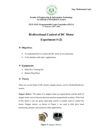
- 1. Eng. Mohammad Aqel Faculty of Engineering & Information Technology Al-AZHAR UNIVERSITY-GAZA ITCE 5319: Programmable Logic Controllers (PLCs) 2nd Semester, 2007 / 2008 Bi-directional Control of DC Motor Experiment # (2) Objectives To understand how to control the DC motor in two directions. To be familiar with relay’s applications. Equipments Delta PLC Training Kit. Banana Plug Wires Theory There are several kinds of DC motors: stepper motors, servos, brushed/brush-less motors. Stepper Motors: The inputs of a stepper motor are signal pulses and the shaft of stepper motor moves between discrete positions proportional to pulses. If the load of the motor is not too great, open-loop control is usually used to control the motor. Stepper motors, as shown in Figure 1, are used in disk drive head positioning, plotters, and numerous other applications. Figure 1: Stepper Motors.
- 2. Servo Motors: The input of a servo motor is a voltage value and the output shaft of the servo motor is commanded to a particular angular position according to the input voltage. Servo motors, as shown in Figure 2, are used in robots and in radio control airplanes to control the position of wing flaps and similar devices. Figure 2: Servo Motors. Constant Speed DC Motors: The input of a DC motor is current/voltage and its output is torque (speed). Figure 3 shows constant speed DC motors. Figure 3: Constant Speed DC Motors. DC Motor Theory Direct Current electric motors operate under a basic principle of electricity: interaction between two magnetic fields positioned at an angle from each other will attract/repel resulting in movement. In the case of a DC electric motor, power is provided to a stator field and an armature creating magnetic fields that are, electrically, about 90 degrees from each other. The resulting attraction/repulsion of the armature from the field generates a torque and the armature turns. The basic components of a DC electric motor include: Frame – Makes up the outer structure of the machine. It is used to mount most of the other components of the motor. Fields – Are coils mounted on field pole pieces that generate a stationary magnetic field. 1
- 3. Interpoles – Are coils that are placed between the field coils that generate a field that is used to prevent excessive sparking of the brushes. Endshields – Also called bearing housings, are used to house the brushes, brush rigging, and to house the shaft bearings, holding the armature centered in the frame. Brush rigging – Holds and positions the brushes above the armature commutator. Usually, a tension device is used to maintain a constant pressure on the brushes. Brushes – Are used to provide DC to the armature. The brushes ride on the commutator. Commutator – Consists of many copper bars that are separated by mica. Each bar is connected to coils in the armature. Armature – Is the rotating portion of the motor that contains coils. There are two conditions necessary to produce a force on a conductor: The conductor must be carrying current. The conductor must be within a magnetic field. There are many methods to control the speed of the DC motor and here are some of them: Varying the voltage applied to either the armature or field circuit. Adding resistant in the armature circuit, but this method is in efficient and not effective at light loads. Adding resistant to the field circuit, and this is efficient method, but not convenient nor as efficient as varying the terminal voltage. The other field of DC motor controlling is controlling its direction, and this is easy done by changing the polarities of its brushes, and this is the main scope of this experiment. The direction of rotation of a DC motor may be reversed using one of these methods: Reversing the direction of the current through the field. Reversing the direction of the current through the armature. The industrial standard is to reverse the current through the armature. 2
- 4. Experimental Procedures 1- Connect the control and power circuit as shown in Figure 4. 2- Supply the circuit with a 12VDC. Figure 4: Control and Power Circuit of DC Motor When the NO push button onr (on right), which control the right direction of motor, the current passes through the coil of the R1. Then the relay will change its contact state, the normally open contact which is connected in parallel with the onr button will be closed. So the current still passes through the coil of R1 (Sealin Circuit). As a result, the DC motor will turn right until the off push button is pressed which will open the circuit. When the NO push button onl (on left), which control the left direction of motor, the current passes through the coil of the R2 and the motor will start to move in the left direction due to the changing of the polarity on the coil of DC motor. The following steps show and explain the idea of controlling the DC motor in two directions and how the control circuit works: 3
- 5. Step 1: After connecting the control and power circuits. 24 V DC 24 V DC off onr R1 R1 R2 onl R2 R2 M R1 R1 R1 R2 R2 0 0 Step 2: At pressing the onr push button. 24 V DC 24 V DC off onr R1 R1 onl R2 R2 R2 M + R1 R1 R1 R2 0 R2 0 Step 3: After releasing the onr push button. 24 V DC 24 V DC off onr R1 R1 onl R2 R2 R2 R1 M + R1 R1 R2 0 0 4 R2
- 6. Step 4: At pressing the off push button 24 V DC 24 V DC off onr R1 R1 R2 onl R2 R2 M R1 R1 R1 R2 0 R2 0 Step 5: At pressing the onl push button. 24 V DC 24 V DC off onr R1 R1 onl R2 R2 + R2 M - R1 R1 R1 R2 0 R2 0 Step 6: After releasing the onl push button. 24 V DC 24 V DC off onr R1 R1 onl R2 R2 + R2 R1 M - R1 R1 R2 0 0 5 R2