Clap switch
•
4 gefällt mir•1,350 views


Empfohlen
Weitere ähnliche Inhalte
Was ist angesagt?
Was ist angesagt? (18)
Ähnlich wie Clap switch
Ähnlich wie Clap switch (20)
Mehr von Palestine Information and Communications Technology Incubator (PICTI) (BIC)
Mehr von Palestine Information and Communications Technology Incubator (PICTI) (BIC) (10)
Kürzlich hochgeladen
Kürzlich hochgeladen (20)
Clap switch
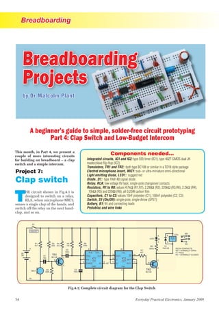
- 1. Breadboarding 54 Everyday Practical Electronics, January 2009 by Dr Malcolm Plant A beginner’s guide to simple, solder-free circuit prototyping Part 4: Clap Switch and Low-Budget Intercom Project 7: Clap switch T HE circuit shown in Fig.4.1 is designed to switch on a relay, RLA, when microphone MIC1, senses a single clap of the hands, and switch off the relay on the next hand- clap, and so on. This month, in Part 4, we present a couple of more interesting circuits for building on breadboard – a clap switch and a simple intercom. Fig.4.1: Complete circuit diagram for the Clap Switch Components needed... Integrated circuits, IC1 and IC2: type 555 timer (IC1); type 4027 CMOS dual JK master/slave flip-flop (IC2) Transistors, TR1 and TR2: both type BC108 or similar in a TO18 style package Electret microphone insert, MIC1: sub- or ultra-miniature omni-directional Light emitting diode, LED1: suggest red Diode, D1: type 1N4148 signal diode Relay, RLA: low voltage 6V type, single-pole changeover contacts Resistors, R1 to R8: values 4.7kΩ (R1,R7), 2.2MΩ (R2), 220kΩ (R3,R6), 2.2kΩ (R4), 10kΩ (R5) and 220Ω (R8), all 0.25W carbon film Capacitors, C1 to C3: values 10nF polyester (C1), 100nF polyester (C2, C3) Switch, S1 (On/Off): single-pole, single-throw (SPST) Battery, B1: 9V and connecting leads Protobloc and wire links Breadboarding Projects
- 2. Breadboarding Everyday Practical Electronics, January 2009 55 Seen from below, the emitter lead is next to the small metal tag. Clock- wise from the emitter are the base, and collector leads. B E C TO18 Component Info IC2, type 4027 JK flip-flop Viewed from above, an indented dot and a ‘half-moon’ shape at one end indicates pin one. Once pin 1 has been identified pins are numbered 1 to 16 going anticlockwise ending up at pin 16 opposite pin 1. TR1 and TR2, type BC108 NPN transistor You need to solder short lengths of 0.6mm diameter insulated wire to the solder pads. One pad is connected to the case of the microphone, so make sure this lead is connected to 0V. MIC 1, electret microphone RLA, relay 6V ener- gizing voltage. This has single-pole changeover switching contacts for switching on and off a separate circuit from the electronic one. How it works The circuit comprises four main building blocks. The first is centred on NPNtransistorTR1,whichswitcheson whenthesoundofahandclapissensed by the microphone. Current flowing through the collector (C) and emitter (E) terminals of TR1 causes a fall in the voltage at its collector, which triggers the second building block. The second building block is based on IC1,a555timerwiredasamonostable.On receivingthesharplyfallingvoltagefrom thecollectorofTR1,IC1producesashort pulseofabout20ms,whichisfedintothe clockterminalofIC2,aJKflip-flop,which makes up the third building block. If IC2 pin 14, the Q output, is logic low, transistor TR2 is off and the relay is not energized. The pulse from the monostable changes the state of the flip-flop and the Q pin goes logic high, switching on TR2, hence energising the relay. Thus TR2 switches on or off, energisingorde-energisingtherelayon subsequent claps, each clap ‘toggling’ the flip-flop. LED1 is optional, but is useful in monitoring the change of the Q output of the flip-flop. The relay connected in parallel with resistorR8andLED1isenergizedwhen LED1lightsanditsnormally-opencon- tact is used to switch external circuits on and off. Note that this circuit must not be used to control mains-powered circuits. Breadboard The Protobloc component layout for the Clap Switch is shown in Fig. 4.2. Whensolderingtheleadstotheelectret microphone insert connecting pads be as quick as possible as it does not takekindlytoexcessiveheat.Notethat one pad is also connected to the case of the mic, so make sure this lead is connected to the board 0V line. Notes Do not use the relay to control power from the mains supply. If you wanttocontrolmains-operateddevices you should seek the help of a qualified electrician. Use the Circuit Tester described in Project 1 to identify the base leads of TR1 and TR2 to confirm that they are both NPN transistors. Once assembled on Protobloc, you will find that LED1 is either on or off, but a sharp clap of the hands will change this by either switching the relay on (LED1 lit) or off (LED1 out). Diode D1 is used to protect the semiconductors, ie the transistors and integrated circuits, from possible dam- age by the sharp surge of voltage known as back EMF, which is generated as the relay switches off. Noadjustmentsarenecessarytothe circuit, but you might like to fashion a small paper cup, a curved reflector,and fititaroundthemicrophonetoenhance the directional sensitivity of the circuit to the sound of a clap. Fig.4.2: Assembly of the Clap Switch on the Protobloc breadboard LOW-BUDGET INTERCOM Viewed from the top, an indented dot and a ‘half- moon’ shape at one end indicates pin one. The pins are numbered anti- clockwise ending at pin 8 opposite pin 1. IC1, type 555 timer IC PIN 1 PIN 1