
Empfohlen
Weitere ähnliche Inhalte
Was ist angesagt?
Was ist angesagt? (20)
Ähnlich wie Uranium corporation of india
Ähnlich wie Uranium corporation of india (20)
Mehr von engineeringwatch
Mehr von engineeringwatch (20)
Kürzlich hochgeladen
Kürzlich hochgeladen (20)
Uranium corporation of india
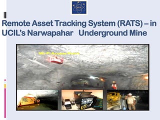
- 1. Remote Asset Tracking System (RATS) – in UCIL’s Narwapahar Underground Mine
- 2. Set-up in 1967, Uranium Corporation of India Ltd (a Public Sector Enterprise) under the Department of Atomic Energy, has the sole mandate to mine and process uranium ore for fuelling the Pressurised HeavyWater Reactors for generation of electricity through nuclear means. URANIUM CORPORATION OF INDIA LTD ECO-FRIENDLY & SOCIALLY RESPONSIBLE MININGWITHTECHNICAL EXCELLENCE An ISO 9001:2008, ISO 14001:2004, IS 18001:2007 company MISSION To Maintain sustained U - fuel supply to the nuclear reactors for energy security Take significant initiatives for meeting national needs and priorities Achieve all round excellence & global standards
- 4. 4 NARWAPAHAR MINE Commissioned in 1995 Entry through 80 decline for movement of trackless equipment 355m deep shaft providing access to deeper levels Most modern, well designed and mechanised underground mine Cut-and-fill method of stoping with ramp as access Waste rock filling along with de- slimed tailings Deployment of state of art equipment like hyd drill jumbos, LHD, LPDT, passenger carrier, scissor lift for drilling and mucking etc.
- 5. THE GENESIS OF CHALLENGE Underground mines, with personnel and equipment working at great depths, require an effective and fool-proof, mine-wide communication system for smooth functioning of mine production and worker safety. With this rationale in view in late 2011, a proposal was mooted to take up a project to address the various challenges involving production management, maintenance downtime and asset tracking in UCIL’s underground mines. UCIL management decided that its modern high production mine at Narwapahar located in the East Singhbhum district of Jharkhand would be the pilot location for the project to validate the IT solutions in the mining domain. Further within Narwapahar mine, Level 4 located 140m (460 feet) below ground was determined as the area where the solution would be piloted. It was decided to take the assistance of M/sTCS (who have certain experience in mining) for providing the necessary technical inputs.
- 8. UNDERSTANDING THE SOLUTION TERMINOLOGIES Wi-Fi is the industry name for wireless LAN (WLAN) communication technology related to the IEEE 802.11 family of wireless networking standards.Wi-Fi is a popular technology that allows an electronic device to exchange data or connect to the internet wirelessly using radio waves. Radio-frequency identification (RFID) is the wireless non-contact use of radio-frequency electromagnetic fields to transfer data for the purposes of automatically identifying and tracking tags attached to objects.The tags contain electronically stored information. Unlike a bar code, the tag does not necessarily need to be within line of sight of the reader and may be embedded in the tracked object.The RFID tag attached to the underground mine truck tracks its movement through the mine area. An IP Phone or VoIP phone or uses voice over Internet Protocol (VoIP) technologies for placing and transmitting telephone calls over an IP network, instead of the traditional public switched telephone network (PSTN).The Cisco make IP phones used in our system gives the full advantage of converged voice and data networks while retaining its convenience and user-friendliness.
- 9. SYSTEM ADAPTATION This challenge was taken up as R & D project of UCIL in collaboration with M/s TCS. The system has been installed at the 4th level (140 m below surface). It has three components, viz. Tracking of Vehicles & Key Personnel. Voice Communication between Key Personnel. Production Monitoring by Trip Counting.
- 10. BASIC SYSTEM The system uses a Wi-Fi based tracking system for real-time and historical tracking of Underground Trackless Equipment. Key Personnel. Wireless voice communication between key personnel in Underground using IP Phones
- 11. System Features A Control Room in underground. A Wi-Fi network in underground. An RFID network underground. The system uses OFC cables for long distance data transmission.
- 12. System Components of Wi Fi network The Wi-Fi is primarily used for tracking of assets, voice communication between key miners and the control room on zoned basis. Access Points: A wireless access point (WAP) is a device that allows wireless devices to connect to a wired network using Wi-Fi WCS: Wireless Control System (WCS) includes tools for wireless LAN planning and design, location tracking, and wireless LAN systems configuration, monitoring, and management. MSE: Mobility Services Engine (MSE) is an appliance-based solution that supports a suite of software services to provide centralized and scalable service delivery. API: An application programming interface (API) is a specification intended to be used as an interface by software components to communicate with each other. Application Data Storage:SQL server 2008 is used as database in this solution.
- 13. System Components of RFID network Individual MT trip count data are gathered by RFID system. RFID Reader: RFID readers use RF waves for communication and therefore must have one or more antennas. The antenna may be externally connected or in the same housing or enclosure as the RFID reader electronics. RFID Tag: The tag transmits information to the reader via antenna, and the reader converts the incoming radio waves into a form that can be read by a computer system. RFID middleware: RFID Middleware communicates with the device; filters redundant data in real time, logs the filtered data along with a time-stamp to a database .The logged data is utilized by the application to create reports of trip count for individual MTs.
- 14. Underground Wi-Fi Network It consists of: ‘Wi-Fi Access Points’ at various locations consisting of LIU (Light Interface Unit) Media Converter Wi-Fi Antenna near Access Points (Range = 75 m) Wi-Fi tags mounted on mine equipment IP Phones for voice communication
- 15. Underground RFID Network THE U/G RFID NETWORK COMPRISES OF: An RFID Reader near grizzly at 4th level where Mine Trucks are unloaded. A pair of RFID antennas (Range :3.0 m) To detect presence of mine truck in close proximity. To stamp mine truck unloading time. RFID tags (passive) mounted on mine trucks
- 16. Underground Control Room It has the following installations Server for storage and processing of time stamped data. A graphic user interface showing Location of mine equipment Location of IP Phones (used by Key personnel) It is connected through OFC cables with Wi-Fi Access Points. RFID Readers.
- 18. Application Development Technology The following table details the software details used to develop the Remote Asset Tracking application. SL No Software Item Specification 1 Operating System Windows Server 2008 R2 Standard 2 Database Software Microsoft SQL Server 2008 R2 Standard 3 Development Software Microsoft visual studio 2010 using vb, asp.net 4 Documentation Software Microsoft Office 2010
- 19. LOGGING SHEETS
- 20. Benefits from the System Implementation of this project has helped in Fast track management of emergency situations by voice communication using IP phones. Faster management of breakdowns to minimize downtime of various mine equipment. Better monitoring of mine truck trips. Generation of real time data for industrial engineering studies for better planning.
- 21. IN CONCLUSION… Our remote RFID asset tracking system is proving to be an optimisation mechanism wherein the movements of the high production equipment are tracked online, instructions provided in case of problems or safety issues and all necessary data transmitted/stored for more effective mine planning. With add-on facilities the project shall be upgraded from the present voice/ data communication to continual video images of the underground workings. The diagnostic modules of all critical underground equipment shall also be interfaced to this system. We have thus proved that if an organization has the will & is not afraid of challenges then nothing is impossible.
- 22. I asked God for water, He gave me an ocean. I asked God for a flower, He gave me a garden. I asked God for a friend, He gave me all of YOU...