Solids Content Sensor-TurbiMax W CUS 41-CUS 41-W
•
0 gefällt mir•722 views

Sensor for service water and solids content measurement based on multi-channel technology. Email: lam.nguyen@vietan-enviro.com HP: 0945 293292

Empfohlen
Empfohlen
Weitere ähnliche Inhalte
Was ist angesagt?
Was ist angesagt? (20)
Andere mochten auch
Andere mochten auch (8)
Ähnlich wie Solids Content Sensor-TurbiMax W CUS 41-CUS 41-W
Ähnlich wie Solids Content Sensor-TurbiMax W CUS 41-CUS 41-W (20)
Mehr von Edress Hauser: Flow Meter, Level, Pressure, Temperature
Mehr von Edress Hauser: Flow Meter, Level, Pressure, Temperature (20)
Kürzlich hochgeladen
Kürzlich hochgeladen (20)
Solids Content Sensor-TurbiMax W CUS 41-CUS 41-W
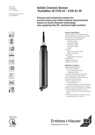
- 1. Technical Information TI 177C/07/en Operating Instructions No. 50088402 Areas of application Optical solids content measurement is indispensable as a regulating variable for operation in following areas: • Sewage treatment plants – Primary sludge – Activated sludge – Returned sludge – Putrefied sludge – Outlet • Paper – Monitoring of sieve water – Water processing • Concrete – Measurement of soiling • Production • Water processing • Water monitoring Benefits at a glance • Measuring range from 0.01 FNU to 100 g/l – from completely clear to completely black • Scratch-proof sapphire windows • Compact shock-proof design • For installations in pipes or basins • Simple commissioning • 3-point calibration and 1-point adjustment • 7 calibration data records according to customer specifications can be stored • Wiper cleaning integrated or retrofitted • Inclined flat sensor surface uses medium flow to increase self-cleaning effect • Permissible distance between sensor and transmitter up to 200 m Solids Content Sensor TurbiMax W CUS 41 / CUS 41-W Process and immersion sensor for service water and solids content measurement based on multi-channel technology, also applying the 90° scattered light method Hauser+Endress Nothing beats know-how Quality made by Endress+Hauser ISO 9001
- 2. Measuring system A measuring system consists of: • TurbiMax W CUS 41 solids content sensor • Liquisys CUM M 223/253 transmitter Functional principle The 90° scattered light method with a measuring frequency in the near-infrared range of light (880 nm) according to ISO 7027 / EN 27027 guarantees a measurement of the turbidity value under standardised, comparable conditions. The excitation radiation of an infrared transmitter strikes the medium at a defined angle of beam. The different refractive indices of the entrance window and the measuring medium (water) are taken into account. Particles in the medium generate a scattered radiation which strikes the scattered light receiver at a defined angle. The measurement in the medium is constantly adjusted with the values of a reference receiver. Digital filter functions with an excellent interference signal suppression and sensor self-monitoring ensure additional measurement reliability. In addition to the turbidity signal, a temperature measurement signal is detected and transmitted. Calibration Every sensor in the “FNU field of application” is carefully factory- calibrated using standard procedures. Other customer- and substance-specific calibrations can also be stored. Depending on the different precise requirements in service or drinking water, special assemblies with the integrated calibration values are provided. For service water measurements, standard specifications are usually sufficient. However, installing the sensor in a pipe or very close to a wall can cause backscatter resulting in a higher signal. To compensate for this, an installation adjustment must be performed. 0.127FNU 12.3 C o Endress + Hauser Flow direction Examples of complete measuring systems left: CUS 41 in CUA 461 retractable assembly right: CUS 41 in immersion assembly ➀ LED ➁ photodiode ➂ photodiode ➃ wiper (optional) 2
- 3. Notes on installation and application Wall distance The effective wall or floor distance can be optimised by aligning with the flat sensor side. The opposite figure shows the influence of this distance on the measurement with bright or dark shading of wall or floor. As a rule, the CUS 41 sensor should be immersed at least 4 cm into the medium to be measured. Self-cleaning Optimum self-cleaning and sufficient wall distance (e.g. in narrow channels) are achieved by turning the inclined sensor surface into the flow direction. Some time after initial operation, the sensor should be checked for dirt. To clean it, wipe with a soft cloth. The most favourable sensor position should be maintained. Should self-cleaning not be sufficient, then we recommend the wiper sensor CUS 41-W or the spray cleaner CUR 4 – especially for media which tend to deposit sludge films or crusts. Installation in immersion assemblies Note When installing CUS 41 in an immersion assembly, such as CYA 611 with a pendulum frame, please note that sufficient wall distance must be maintained during the measuring process. The assembly should be installed where a minimum wall distance of 15 cm is guaranteed even with varying medium levels or changing flow conditions. Installation in a suspension assembly with chain must therefore be avoided. Mounting • Remove cover from holding tube. • Pull connection cable through holding tube without twisting it; screw in sensor and turn to the stop. Note: First undo twists in cable by reverse twisting. • Put on cover. • Secure sensor cable to transverse pipe and connect it to the instrument, or if used, to the junction box. TurbiMax W CUS 41 sensor installed in CYA 611 assembly with pendulum frame 1500 950 2000 450 150 120 1490 Assembly holder CYH 101 with weather protection cover CYY 101 for field transmitter CUS 41 sensor Medium flow Self-cleaning by flow against the inclined sensor surface FNU 20 10 10 20 30 40 Wall or floor dark (non-reflecting) Wall or floor bright (reflecting) distance [cm] Dependence of the measurement on the wall or floor distance 3
- 4. Pipe installation Notes • The pipe diameter must be at least DN 100 when shiny materials (e.g. stainless steel) are used. • Install the sensor in places with uniform flow conditions. Do not install it in places where air may collect, where foam bubbles are likely to form (➀) or where suspended solids may settle (➁). • Install the sensor surface against the medium flow. Mounting • Lead connection cable through sleeve and hexagon coupling without twisting it. • Insert sensor body into the sleeve so that the O-ring adjoins under the G 1" screw thread in the sleeve. Note marking pin and marking hole on the sleeve. • Install CUS 41 into the adapter in such a way that the acute-angled edge of the sensor lies opposite to the marking hole and points away from it. The marking hole renders the sensor orientation clearly identifiable. Welding neck DN 50 / ANSI 2" Material Order no. Stainless steel 1.4571 (SS 316Ti) 50080249 Polyvinyl chloride PVC 50080250 Polypropylene PP 50080251 ➀ ➀ ➁ ➁Orientation and positions of CUS 41 with CUA 120-A/-B adapter or CUA 461 retractable assembly Nut 46 AF (G 1") Material PVC black O-Ring EPDM ∅ 60 ∅ 50 9293 16~20 left: CUA 120-B adapter with welding neck DN 50 / ANSI 2" (accessory) and lap joint flange DN 50 / ANSI 2" (to be provided by customer) right: Process connection adapter for pipe diameter greater than 80 mm ∅ 40 217 191 gn wt ye bn Outer screen Com A Com B +UB –UB CUS 41 sensor 75 93 ∅ 165 Holes for DN 50 und ANSI 2" 4
- 5. Pipe installation (continued) For a description of the assembly, refer to Technical Information TI 134C/07/en, order no. 50073613. Installation in flow assemblies Notes on installation • The medium should, if possible, flow into the assembly from below. If the flow assembly must be installed in a horizontal instead of a vertical position, then install the sensor in the 3 o'clock or 9 o'clock position. This helps avoid air pockets. • Installing the sensor parallel to the medium flow is necessary: – for turbidities < 5 FNU to minimise wall reflection effects. Also carry out installation adjustment! – in conjunction with the spray head CUR 3. • Installing the sensor against the medium flow is used to increase self-cleaning effects: – in heavily soiled media with turbidities > 15 FNU, where wall reflections can in any case be neglected due to the high absorption rate. Sensor orientation parallel to the medium flow The sensor is inserted into the union nut. Loosely tighten the hexagon coupling on the G 1" thread of the sensor. When the sensor is inserted with the sleeve on, the fitting hole on the upper edge of the assembly accommodates the locking pin. Position the sensor by turning it in such a way that the sharp edge formed by inclined sensor surface and sensor cylinder lies opposite the marking pin and points away from it. The spray-head connection in the T-section of the CUA 250 is now located over the sensor surface. Sensor orientation against the medium flow Position the sensor by turning it until the sharp edge formed by inclined sensor surface and sensor cylinder lies turned by 90° opposite the marking pin and points in the flow direction of the medium. Hand-tighten the hexagon nut. withsensorextendedupto650 withsensorretracted300 175 125 1 250 2 100 90 Flow direction Dimensions of Probfit CUA 461 assembly 1 Process connection DIN Flange DN 50 or ANSI 2" 2 Process connection adapter (accessory, see p. 4) Installed parallel to the medium flow Installed against the medium flow 5
- 6. Installation in flow assemblies (continued) FlowFit W CUA 250-A, CUA 250-B • Lead connection cable through union nut, sleeve and hexagon coupling without twisting it. • Insert sensor body into the sleeve so that the O-ring adjoins under the G 1" screw thread in the sleeve. Note locking pin and marking hole on the sleeve. FlowFit W CUA 250-A, CUA 250-B with CUR 3-1 spray head • Screw the CUR 3-1 spray head into the CUA 250 assembly in place of the lateral plug screw. • Mount the CUS 41 sensor as above with parallel sensor installation to ensure optimum self-cleaning. ∅ 58 ∅63 ∅73 142 264 227 1¼" 53 ¾" 29 22 3 9 25 A View A Dimensions CUA 250-A/-B 30 71 Dimensions CUA 250-A/-B with CUR 3-1 spray head 6
- 7. Turbidity sensor with wiper cleaning The CUS 31/41-W sensors are both equipped with a screen wiper. The cleaning times and intervals are entered into the Liquisys M CUM 223/253 transmitter. For optimum cleaning, wiper timing is adjustable. Checking the rest position • Pull the sensor from the assembly. • Moisten the sensor surface. • Set type of cleaning and cleaning times on the transmitter and start the wiping cycle. • Check the wiper movement (cycle) on the sensor. The wiper must reach the rest position (see figure). Caution: Do not move the wiper arm by hand! Note: If the wiper comes to rest over the measuring windows, then measuring errors will result. Maintenance and cleaning Deposits on the sensor optics may result in inaccurate measurement. Therefore the sensor must be cleaned at regular intervals. The intervals are specific to each installation and must be determined during operation. Clean the optics with the following agents depending on the type of soiling: • Clean the sensor mechanically using a soft brush. Then rinse thoroughly with water. Type of soiling Cleaning agent Limestone deposits Short treatment with commercial deliming agent Oily and greasy soiling Cleaning agents based on water-soluble surfactants (e.g. household dish detergents) Other types of soiling With water and brush Warning: • Do not touch the optics with sharp-edged objects. • Do not scratch the optics. ➀ Rotating sense 1 Wiper arm LED Photodiodes Support plate Rotating sense 2 ➀ Rest position of the wiper arm Tolerance range: ±20° 7
- 8. How to order Technical data Measuring principle nephelometric 90° NIR scattered light according to EN 27027 Measuring ranges 0.00 ... 9999 FNU, 0.00 ... 9999 ppm, 0.0 ... 300 g/l, 0.0 ... 200.0% (depending on the type of sample) Wavelength 880 nm Optical reference compensation by reference photodiodes Factory calibration formazine standard and SiO2 Temperature / pressure 25 °C / 6 bar ... 50 °C / 1 bar Connecting cable 4-core with terminal bushes Max. cable length 200 m Temperature sensor NTC Nominal operating range –5 ... +50 °C Storage temperature range –20 ... +60 °C Ingress protection IP 68 Materials Sensor support plate, shaft, cable PVC Optical windows sapphire Flow assemblies PVC Solids content sensor TurbiMax W CUS 41 Sensor A Sensor in standard version W Sensor with integrated wiper Cable length 2 Connecting cable 7 m 4 Connecting cable 15 m 9 Connection cable according to customer specifications CUS 41- complete order code Endress+Hauser GmbH+Co. - Instruments International - P.O. Box 2222 D-79574 Weil am Rhein Tel. (07621) 975 - 02 Fax (07621) 975345 Hauser+Endress Nothing beats know-how TI 177C/07/en/01.98 Printed in Germany / DT / CV5 (50088402)