Electromechanical Level Measuring System-Silopilot M FMM50
•
1 like•1,333 views

The document provides technical information about the Silopilot M FMM50 electromechanical level measuring system. It can measure levels in bunkers, silos, tanks, and vessels up to 70 meters. The system uses a sensing weight attached to a measuring tape that is lowered into the vessel and detects the surface of the material. It provides a 4-20 mA output signal representing the measured level and optional relay outputs. The document discusses installation, operation, specifications and accessories for the Silopilot M FMM50.

Recommended
More Related Content
What's hot
What's hot (20)
Similar to Electromechanical Level Measuring System-Silopilot M FMM50
Similar to Electromechanical Level Measuring System-Silopilot M FMM50 (20)
More from Edress Hauser: Flow Meter, Level, Pressure, Temperature
More from Edress Hauser: Flow Meter, Level, Pressure, Temperature (20)
Recently uploaded
Recently uploaded (20)
Electromechanical Level Measuring System-Silopilot M FMM50
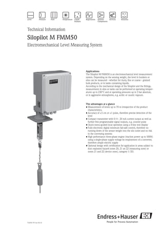
- 1. Technical Information Silopilot M FMM50 Electromechanical Level Measuring System Applications The Silopilot M FMM50 is an electromechanical level measurement system. Depending on the sensing weight, the level in bunkers or silos can be measured - whether for dusty, fine or coarse - grained bulk products, or in tanks containing liquids. According to the mechanical design of the Silopilot and the fittings, measurement in silos or tanks can be performed at operating temper- atures up to 230°C and at operating pressures up to 3 bar absolute, or in aggressive atmospheres, e.g. acidic or caustic vapours. The advantages at a glance • Measurement of levels up to 70 m irrespective of the product characteristics. • Accuracy of ±5 cm or ±1 pulse, therefore precise detection of the level • Compact transmitter with 0/4 - 20 mA current output as well as further free programmable signal outputs, e.g. counter pulse • Quick menu-guided local operation using a 4-line text display • Fully electronic digital minimum fail-safe control, therefore no running down of the sensor weight into the silo outlet and no risk to the conveying systems • High performance three-phase engine (traction power up to 500N) using a single-phase supply voltage by employment of a converter, therefore simple electric supply • Optional design with certification for application in areas subject to dust explosion hazard zones 20, 21 an 22 (measuring zone) or zones 21 and 22 (device zone), category 1/2D. TI395F/97/en/04.10
- 2. 2 Silopilot M FMM50 Endress+Hauser Table of contents Function and system design ......................................... 3 Measuring principle ...................................................................... 3 Measuring device .......................................................................... 4 Device variants ............................................................................. 4 Input ............................................................................ 5 Measured value ............................................................................ 5 Measuring range ........................................................................... 5 Measuring cycle ............................................................................ 5 Measuring tolerance ...................................................................... 5 Inputs ........................................................................................... 5 Output ......................................................................... 6 Output signal ................................................................................ 6 Malfunction signal ......................................................................... 6 Linearization ................................................................................. 6 Auxiliary energy .......................................................... 7 Supply voltage ............................................................................... 7 Cable entry ................................................................................... 7 Arrangement of the terminals ........................................................ 7 Electrical connection .................................................... 8 Supply voltage ............................................................................... 8 Current output .............................................................................. 8 Relays ........................................................................................... 8 Input (active) ................................................................................ 9 Input (passive) .............................................................................. 9 Operating conditions .................................................. 10 Sensing weight ............................................................................. 10 Mounting location ........................................................................ 10 Preparing for mounting ................................................................ 11 Mounting of the sensing weight ................................................... 11 Mounting of the Silopilot .............................................................. 12 Ambient conditions ...................................................................... 12 Process conditions ........................................................................ 12 Dimensions ................................................................. 13 Housing dimensions (with standard wiper 230 mm) ..................... 13 Dimensions extended wiper ......................................................... 14 Dimensions process connection (standard version) ........................ 14 Dimensions process adapter extension (accessory) ........................ 15 Dimensions optionally window and external start button .............. 15 Sensing weights .......................................................... 16 Normal weight ............................................................................. 16 Umbrella weight .......................................................................... 17 Bag weight ................................................................................... 17 Cage weight ................................................................................. 17 Oval float ..................................................................................... 17 Bell weight .................................................................................. 17 Select recommendations ............................................................... 17 Controls and instrumentation ..................................... 18 Control concept ........................................................................... 18 Display ........................................................................................ 18 Controls ....................................................................................... 19 Local control ................................................................................ 19 Safety instructions ....................................................... 20 Features of the EX version ............................................................ 20 Use in accordance with directives ................................................. 20 Assembly instructions ................................................................... 20 Ordering information .................................................. 21 Silopilot M FMM50 ..................................................................... 21 Comments regarding the product structure ................................... 23 User-specific settings .................................................................... 23 Accessories ................................................................. 25 Technical data ............................................................. 26 Mechanical .................................................................................. 26 Electrical ...................................................................................... 26 Certificates and approvals ........................................... 27 CE symbol ................................................................................... 27 Ex approvals ................................................................................ 27 External standards and guidelines ................................................. 27 Supplementary documentation ................................... 27 Operating instructions .................................................................. 27 Safety instructions ........................................................................ 27
- 3. Silopilot M FMM50 Endress+Hauser 3 Function and system design A measuring tape, loaded with a sensing weight, is lowered into the bunker or silo. When the weight meets the surface of the product the tension on the measuring tape is relaxed and this is detected by the Silopilot electronics. Empty calibration (E) Full calibration (F) = maximum measu- rement range Silopilot M FMM50 Block distance 0% 100% D L level (L) = empty calibration (E) – distance determined to surface of product (D) Minimum move distance Determination of the measured value The measured value is transmitted to the 0/4 - 20 mA current output. The sensing weight now runs back up to the start position and the measured value is retained until the next measurement is performed. The current output signal represents the level (L). The unit is delivered with default values for the maximum measuring range according to the unit configuration (see ordering information). The menu-guided programming using the 4-line text display assures easy and fast adjustment to the bunker or silo geometry. During the entire measuring process (lowering and hoisting of the sensing weight) the Silopilot can also transmit pulses (relay output) corresponding to the length of the measuring tape, which can be recorded by a control unit or by an electromechanical counter. Both individual measurements and periodic measurement sequences can be performed. The measurement can then be initiated manually (e.g. external start button) or periodically (e.g. programmed function of the Silopilot). Measuring principle
- 4. 4 Silopilot M FMM50 Endress+Hauser Measuring device The Silopilot M FMM50 is a compact transmitter. In contrast to the measuring device Silopilot FMM760 (Z) with control unit ZAD423, the entire microprocessor-controlled electronic system is integrated into the Silopilot. The measuring unit offers comprehensive input and output facilities. For details please refer to the ordering information. To ensure compatibility with older installations using the control unit ZAD423, an appropriate pulse output is provided for connection to the control unit. Ex version For application in areas subject to explosion hazards due to flammable dusts, Zones 20, 21 and 22 (measuring zone) or Zones 21 and 22 (device zone), category 1/2D Mechanical and electrical options • Ambient temperature: -20°C to +70°C or -40°C to +70°C by using the self-control housing heater (Ex version down to -35°C) Also recommended in case of moisture in vessels and for ambient temperatures below 0°C. • Process pressure: 0.8 to 1.1 bar absolute or 0.8 to 3 bar absolute • Process temperature: -20°C to +70°C (also Ex version) or -20°C to +150°C or -20°C to +230°C • Standard for two power supply ranges: 90 - 127 VAC, 50/60 Hz or 180 - 253 VAC, 50/60 Hz • Traction power: 250 N for light bulk solids like powder, granulate or grain 500 N for heavy bulk solids like gravel, sand or cement • Tape wiper: - Length: 230 mm, 500 mm or 1000 mm - Material: Alu/steel or stainless steel • Optional: - Four supplementary relay outputs - External start button and gauge-glass in the device cover - Enhanced climate resistance (at ambient temperature range -20°C to +70°C) - Housing coated (RAL 5012, cover RAL 7035), bubble level for mechanical arrangement • Sensing weight: A diverse range of sensing weights is available according to the application. For details please refer to the relevant section heading. Device variants
- 5. Silopilot M FMM50 Endress+Hauser 5 Input The measured value is the distance between the flange of the Silopilot minus a blocking distance and the surface of the product. The filling level is computed taking into account the fixed given calibration values, e.g. the empty calibration (height of the silo). The filling level can be converted to other values as desired, e.g. volume or mass, by the application of linearization. Measured value • max. 70 mMeasuring range Two inputs (active/passive) are available for external operation of the Silopilot: • Active input: - Connection of an external voltage - Input voltage range: 12 ... 24 VDC • Passive input: - Connection of an external command device, e.g. switch/button, relay contact - Contact rating: max. 5 mW • Input polarity: - Normally open or normally closed • Start pulse length: - min. 200 ms • Optional: - External start button Inputs • ± 5 cm (irrespective of the selected measuring range)Measuring tolerance Measuring cycle Please observe the minimum time (TM ) for one measuring cycle with the Silopilot M FMM50 according to the measuring range (MR) and the ambient temperature (Ta ). This minimum time must be taken into account in all types of measuring. TM [minute] 70 60 50 40 30 20 10 10 20 30 40 50 60 70 MR [m] Ta =70°C Ta =60°C Ta =50°C Ta =40°C Ta =30°C Ta =20°C Ta = ambient temperature; MR = measuring range 5 Disregarding this can lead to undue warming and result in failure. We recommend not to go below a time of 5 minutes for one measuring cycle.
- 6. 6 Silopilot M FMM50 Endress+Hauser Output • 0/4 - 20 mA current output, active • 2 relay outputs (optional 6 relay outputs) - Contact load capability: 250 VAC, 6 A - Contact material: silver-cadmium-oxide, gold-flashed • Selectable relay functions: - Counter pulse: emits pulses equivalent to the length of the rolled-out tape - Reset pulse: pulse before new measurement, e.g. reset of an external counter - Tape reverse: indication of the lower tape direction reversal - Ascent of sensing weight: indication of ascent of the tape, e.g. fade-out the counter pulses - Upper park position of sensing weight: indication of upper park position, e.g. end of measurement - Measurement active: indication of an active measurement, e.g. lock of filling equipment - Alarm: output alarm states - Maintenance interval: notice to maintain the Silopilot - Limit value: output level limit value (Note: A selected threshold with associated hysteresis applies for all relays, individual settings for each relay are not possible.) Output signal Malfunction signal can be called up via the following interfaces: • Local indication: - Error symbol - Error code with text indication • Current output, programmable status: - Minimum: minimum current value <=3.6 mA (4 - 20 mA) or 0 mA (0 - 20 mA) - Maximum: maximum current value + 10% (≈22 mA) • Relay outputs (alarm function) Malfunction signal The linearization function of the Silopilot facilitates conversion of the measured value into engineering units such as cubic metres or hectolitres. If the filling level is not uniformly proportional to the volume within the set measuring range, then a linearization curve can be entered using a maximum of 32 reference values. Silopilot M FMM50 Levelpoints 8 7 6 5 4 3 2 1 Output signal Volume 0 25 50 75 100% Example of linearization using 8 reference values Linearization
- 7. Silopilot M FMM50 Endress+Hauser 7 Highest measurable point The highest measurable point is given by the blocking distance (see figure "Determination of the measured value" on page 3) plus a minimum descent length of 20 cm. This maximum length must be considered on input of the maximum measuring range (Full calibration, see page 3). The individual value for the blocking distance is preset on delivery and only needs to be adjusted when changing the sensing weight for example, the relevant input option can be found in the menu. When using the normal weight in connection with the 230 mm tape wiper, the blocking distance amounts to 0.8 m and the highest measurable point is 1 m under the flange of the Silopilot. Auxiliary energy Supply voltage Cable entry Arrangement of the terminals • 90 - 127 VAC, 50/60 Hz or 180 - 253 VAC, 50/60 Hz • Power consumption: - without optional heater: max. 230 VA - with optional heater: max. 250 VA • M25 x 1.5 • Cable gland: - Material: plastic - Colour: grey (EX version: black) Terminal 1 Terminal 2 Terminal 3
- 8. 8 Silopilot M FMM50 Endress+Hauser Supply voltage L1 N PE Term. 1.1 Term. 1.2 Term. 1.3 Supply voltage Terminal 1 Connecting the supply voltage The supply voltage (mains voltage) is connected to the plug-in terminals on terminal block 1. The maximum cable cross-section is 2.5 mm2 . You should use a fuse to protect the power supply against short-circuit. 0/4 - 20 mA current output I+ I- Signal evaluation 0/4 – 20 mA Term. 3.9 Term. 3.10 Terminal 3 Connecting the current output The active 0/4 - 20 mA current output is connected to the plug-in terminals on terminal block 3. The maximum cable cross-section is 1.5 mm2 . Normal installation cables are sufficient for making the connections. Relays Term. 2.1 Term. 2.4 Term. 2.7 Term. 2.10 Term. 2.13 Term. 2.16 Term. 2.2 Term. 2.5 Term. 2.8 Term. 2.11 Term. 2.14 Term. 2.17 Term. 2.3 Term. 2.6 Term. 2.9 Term. 2.12 Term. 2.15 Term. 2.18 Relay 1 Relay 2 Relay 3 Relay 4 Relay 5 Relay 6 Terminal 2 (optional) Connecting the relay outputs (rest position) The connection cables are terminated on the plug-in terminal block 2, to relay 1 and relay 2, and optionally up to relay 6. The maximum cable cross-section is 1.5 mm2 . Normal installation cables are sufficient for making the connections. The individual circuits must have a maximum of 6 A fuse protection. Note! The rest position matches with the position of the relays without power supply, this represents the alarm condition if the function "alarm" is selected. Electrical connection
- 9. Silopilot M FMM50 Endress+Hauser 9 Input (active) + – Relay contact, switch ... 12 ... 24 VDC Term. 3.1 Term. 3.2 Input 1 Term. 3.3 Term. 3.4 Input 2 Terminal 3 Connecting the active signal input The active input signal is connected to the plug-in terminals on terminal block 3. The maximum cable cross-section is 1.5 mm2 . Normal installation cables are sufficient for making the connections. Input voltage range: 12 ... 24 VDC Input (passive) Relay contact, switch ... Term. 3.5 Term. 3.6 Input 1 Term. 3.7 Term. 3.8 Input 2 Terminal 3 Connecting the passive signal input The passive input signal is connected to the plug-in terminals on terminal block 3. The maximum cable cross-section is 1.5 mm2 . Normal installation cables are sufficient for making the connections. Contact rating: max. 5 mW Notice about the inputs: The signal inputs (active/passive) can only be used alternatively. A double connection from input x active and passive can not be used. The minimum start pulse length is 200 ms.
- 10. 10 Silopilot M FMM50 Endress+Hauser Planning the mounting location Select a mounting location on the bunker or silo such that product falling inside during filling, or accu- mulations of product collapsing inward, cannot cover the sensing weight nor damage the measuring tape. Take due account of the shape and location of the product inflow cone and the outflow funnel within the vessel. The measuring path should not pass too close to any internal fixtures or struts, so that the measuring tape will not brush against them if the sensing weight swings around. Select the length of the tape wiper such that the sensing weight is outside of the mounting flange. Silopilot M FMM50 DistanceDistance *1 Inflow 100% X % Y % 0% Product cone Slope Outflow funnel *2 *2 *1 Accumulations (product build-up at the vessel wall) *2 Select a measuring location at the approximate mid-point of the slopes. Selection of the mounting location Operating conditions Sensing weights (see relevant section heading) When selecting the sensing weight, the following points should be taken into consideration: • The sensing weight must not sink into the product during measuring, nor should it be diverted by the product inflow cone. • The sensing weight must be suitable for the chemical properties of the product and for the temperature inside the bunker/silo. Special designs for individual applications can be offered on request. Sensing weight Mounting location
- 11. Silopilot M FMM50 Endress+Hauser 11 The Silopilot is best mounted on a counter flange DN100 PN16 (connection dimensions according to EN 1092-1) or a flange having the same connection dimensions. The counter flange must be mounted exactly horizontal so that the Silopilot can also be mounted horizontally onto it (maximum angle of inclination 2°). A suitable installation aid (Bubble level) can be found inside the devices with coated housing which, with the electronics cover opened, can be used for alignment. When installing outside, fit a protection hood or install a weather protection roof. Weather protection Preparation for mounting Mounting of the sensing weight Normal weights, umbrella weights and bag weights (see overview of sensing weights under the relevant section heading) can be passed through the DN100 mounting flange into the bunker/silo. Tape fastening Rotating bush Normal weight The measuring tape is pressed into the tape fastening by two screws. A third screw secures the chain. A rotating bush is mounted at the lowest extent of the chain, to accommodate any turning motion of the sensing weight. The weight fixings (tape fastening, chain and rotating bush) are made from galvanized steel or stainless steel. Mounting of the sensing weight
- 12. 12 Silopilot M FMM50 Endress+Hauser When using larger sensing weights, such as cage weights, bell weights, floats and some bag-type weights, access provision must be present in the construction of the bunker/silo for installation of these weights (see illustration). Rod with hooked end Access hatch Silopilot M FMM50 Tape wiper Measuring tape e. g. cage-type Lower carefully into vessel! For details of these installations please refer to the operating instructions! Mounting of larger sensing weights Mounting of the Silopilot Ambient temperature at the Silopilot: • -20 ... +70°C • -40 ... +70°C by using the self-control housing heater (Ex version down to -35°C) Ambient conditions Process temperature: • -20 ... +70°C (standard and Ex version) • -20 ... +150°C • -20 ... +230°C Process pressure (in the vessel): • 0.8 ... 1.1 bar absolute (standard and Ex version) • 0.8 ... 3.0 bar absolute (high pressure version) Note! Use a nozzle of 400 - 500 mm height with process temperatures from +70°C up to 150°C (Silopilot M FMM50-********2***) for a temperature reduction. In this case a wiper length of 500 mm must be used. Use a nozzle of 900 - 1000 mm height with process temperatures from +70°C up to 230°C (Silopilot M FMM50-********3***) for a temperature reduction. In this case a wiper length of 1000 mm must be used. Process conditions Fit a sealing gasket on the flange (particularly in case of pressurised bunker/silo). Carefully guide the sensing weight into the bunker/silo. When using larger sensing weights, please refer to the section heading "Mounting of the sensing weight". Now place the Silopilot onto the flange and secure it using four M16 bolts of suitable length. Please note the following: • Mount the Silopilot horizontally (see under section heading "Preparation for mounting"). • Take the position of cable entries for electrical connections into consideration. When installing in bunkers/silos with heavy dust loadings, a slight positive pressure can be generated at the Silopilot by connecting a compressed air line to its mounting flange (airflow quantity as required). There is a G1⁄4 female connection provided for this purpose (see dimensions of the standard version).
- 13. Silopilot M FMM50 Endress+Hauser 13 Dimensions m – Dirty compartment n – Electronics compartment o – Rinsing air connection G¼ – bore hole 22598349 305 339 196 260 m n o Housing dimensions Housing dimensions (with standard wiper 230 mm)
- 14. 14 Silopilot M FMM50 Endress+Hauser 515or1015 Dimensions of the wiper extension Ø95*1 Ø160 170 Ø180 18 186 *1 Minimum dimension for installing the wiper mechanism and the standard weight Hole dimensions DN100 PN16 (according to EN 1092-1) Dimensions of the standard process connection Dimensions of the extended tape wiper Dimensions of the process connection (standard version)
- 15. Silopilot M FMM50 Endress+Hauser 15 790 Ø95*1 Ø160 Ø180 Ø220 18 max.210 *1 Minimum dimension for installing the wiper mechanism and the standard weight Dimensions of the process adapter extension Note! Use a nozzle of 400 - 500 mm height with process temperatures from +70°C up to 150°C (Silopilot M FMM50-********2***) for a temperature reduction. In this case a wiper length of 500 mm must be used. Use a nozzle of 900 - 1000 mm height with process temperatures from +70°C up to 230°C (Silopilot M FMM50-********3***) for a temperature reduction. In this case a wiper length of 1000 mm must be used. 73 82 Start button Dimensions of the optional window Dimensions of sensing weights (see relevant section headings) Dimensions of the process adapter extension (accessory) Dimensions of the optional window and external start button
- 16. 16 Silopilot M FMM50 Endress+Hauser Sensing weights • Application: For coarse bulk solids, e.g. coals, ores or stones and granulates. • Materials: Steel or stainless steel • Weight: 3.5 kg • The spike can be screwed off. • If the bunker/silo has a downstream crushing or milling system, we recommend using the electrical signal function "tape breakage” or the use of a cage weight to avoid damaging the system in the event of the sensing weight breaking free. Normal weight (Option B/C) Ø55 Ø8 110230 approx.635 edgelength400 approx.635 Øapprox.150 approx.300 400 194 approx.370 approx.670 Ø315 approx.190 approx.485 Ø315 300 approx.600 m Option B/C n Option D/E o Option G q Option M p Option H/J r Option K/L
- 17. Silopilot M FMM50 Endress+Hauser 17 • Application: For very light and loose bulk solids, e g. flour or coal-dust. The umbrella weight has a large square surface area which prevents it from sinking deeply into the product. • Materials: Steel or stainless steel, polyester • Weight: 3.5 kg • Maximum permissible temperature: +150°C • When folded closed, the weight can be passed through the DN100 mounting flange into the bunker. • Application: In bunkers to which e.g. mills are connected down-stream. The bag contains whichever product is contained within the bunker. • Materials: Bag made of polyester, all metal parts made from stainless steel. • Weight: 0.25 kg (empty) / 3.5 kg (filled) • Maximum permissible temperature: +150°C • Bind the bag closed at the top so that the contents cannot fall out if the bag tips over on the slope of a product cone. • Application: For fine bulk solids in silos with relatively small outlet openings that must not be blocked by a sensing weight which has broken free. Also suitable for high temperatures for which a bag may not be used. • Materials: Steel or stainless steel • Weight: 3.5 kg • The weight could become lodged over the product outlet – but would allow the bulk solid to pass through. Since the cage weight cannot enter a conveyor system (e.g. cellar wheel feeder or screw conveyor), no damage can result. • Application: For liquids, e.g. fuel oil, also for granulates. • Material: Hard PVC • Weight: The float must be filled with product to a total weight of 3.5 kg (empty weight 1.3 kg). • Maximum permissible temperature: +70°C • Use of the oval float in the "Dust ignition-proof" version is not permitted! • Application: For light and loose bulk solids; especially where higher temperatures and particular characteristics preclude the use of an umbrella weight. • Materials: Steel or stainless steel • Weight: 4.3 kg When selecting the sensing weight the following points should be considered: • The sensing weight may not sink into the product nor be diverted by contact with the product cone during the measuring procedure. • The sensing weight must be suited for the chemical characteristics of the product and the temperature within the bunker/silo. Selection recommendations Umbrella weight (Option D/E) Bag weight (Option G) Cage weight (Option H/J) Oval float (Option M) Bell weight (Option K/L)
- 18. 18 Silopilot M FMM50 Endress+Hauser Controls and instrumentation Parameters for the Silopilot are set locally using a large 4-line text display, which can also display the existing measured values. The menu guidance and integrated help texts ensure quick and safe commissioning. Control concept Display Liquid crystal display (LC-display) • Four lines • 20 characters per line • Display contrast adjustable by using a key combination Liquid crystal display m e a s u r e d v a l u e 0 0 0 6 3 . 4 2 % █ █ █ █ █ █ █ █ █ █ █ █ _ _ _ _ _ _ _ _ Controls and instrumentation
- 19. Silopilot M FMM50 Endress+Hauser 19 The control elements are located within the housing (exception: external start button) and can be operated after opening the electronics cover. The Silopilot may only be operated with closed cover in areas subject to explosion hazards! Function of the keys The LC-display can be used for configuration direct to the Silopilot using 3 keys. A menu control is used to set all unit functions. The menu comprises function groups and functions. Application parameters can be displayed and set within the functions. The user is guided through the complex start-up procedure. m e a s u r e d v a l u e 0 0 0 6 3 . 4 2 % █ █ █ █ █ █ █ █ █ █ █ █ _ _ _ _ _ _ _ _ m e a s u r e d v a l u e 0 0 0 6 3 . 4 2 % █ █ █ █ █ █ █ █ █ █ █ █ _ _ _ _ _ _ _ _ G r o u p s e l e c t i o n √ b a s i c s e t u p i n p u t s a n d o u t p u t s m e a s u r e m e n t p a r a m . e m p t y c a l i b r . 0 0 1 2 0 . 0 0 0 m d i s t a n c e f l a n g e t o m i n . f i l l i n g Label ↓ Position ↓ Bargraph ↑ Value ↑ ↑ Unit Selection list → Function groups → Functions Help text ↑ X F001 F002 F003 F004 F005FG00 FG01 FG02 FG03 FG04 FG05 FG06 FG07 F001 X X X F F F F O O S S ... ... Local control Key(s) Function Oor V - Navigation upward within the menu list - Editing of numerical values within a function Sor V - Navigation downward within the menu list - Editing of numerical values within a function Xor Z - Navigation to the left within a function group F - Navigation to the right within a function group - Enter Oand F or Sand F Contrast settings of the LCD - O and F increase the contrast - S and F decrease the contrast F - Start measuring (only in function 000) man. start Controls Local control #
- 20. 20 Silopilot M FMM50 Endress+Hauser Safety instructions • Designation: 0 II 1/2D IP67 T99°C • Certification number: BVS 05 ATEX E 049 Features of the ATEX version Use in accordance with directives • Operation of the Silopilot in areas subject to explosion hazards is only permissible with the housing closed. • The Silopilot with "Ex" design may only be repaired by the manufacturer. • The requirements of EN 50281-1-2, e.g. with respect to dust deposits and temperatures must be adhered to under all circumstances. • Please take care that the ambient temperature will not be greater than +70°C, even if the process temperature range is between +70°C and +230°C. Use special equipment (e. g. process adapter extension) or select possible mounting position to keep this condition. Assembly instructions Zone 21 Zone 20 - FMM50 Assembly instructions (ATEX) For details please refer to the XA425F-A/97/a3.
- 21. Silopilot M FMM50 Endress+Hauser 21 Ordering information Ordering information for Silopilot M FMM50 10 Approval: A Non-hazardous area B ATEX II 1/2D IP67 T99°C Y Special version, to be specified 20 Housing: 1 Aluminium 2 Aluminium, coated 9 Special version, to be specified 30 Motor traction power: A max. 250 N, bulk density low B max. 500 N, bulk density high Y Special version, to be specified 40 Measuring range: 1 25 m 2 35 m 3 50 m 4 70 m 9 Special version, to be specified 50 Max. nozzle height; tape wiper A 230 mm, alu/steel B 230 mm, stainless steel C 500 mm, alu/steel D 500 mm, stainless steel E 1000 mm, alu/steel F 1000 mm, stainless steel Y Special version, to be specified 60 Power supply: 1 180 - 253 VAC, 50/60 Hz 2 90 - 127 VAC, 50/60 Hz 9 Special version, to be specified 70 Output: A 0/4 - 20 mA + 2x relay, adjustable: counting / reverse / upwards / max. position / alarm / limit / measuring active B 0/4 - 20 mA + 6x relay, adjustable: counting / reverse / upwards / max. position / alarm / limit / measuring active Y Special version, to be specified
- 22. 22 Silopilot M FMM50 Endress+Hauser Continuation ordering information for Silopilot M FMM50 80 Ambient temperature: A Range -20 ... +70°C B Range -40 ... +70°C + heater (ATEX II 1/2D min. -35°C) C Range -20 ... +70°C + enhanced climate resistance Y Special version, to be specified 90 Process temperature: 1 Range -20 ... +70°C 2 Range -20 ... +150°C 3 Range -20 ... +230°C 9 Special version, to be specified 100 Process pressure: 1 0.8 ... 1.1 bar absolute 2 0.8 ... 3.0 bar absolute 9 Special version, to be specified 110 Sensing weight: A without B Steel C Stainless steel D Steel + umbrella E Stainless steel + umbrella G Medium bag H Steel cage J Stainless steel cage K Steel bell L Stainless steel bell M Oval float (PVC) Y Special version, to be specified 120 Additional option: 1 Basic version 2 Window + external start button 9 Special version, to be specified FMM50- Order code
- 23. Silopilot M FMM50 Endress+Hauser 23 The following limitations apply to devices with an ATEX license: • Ambient temperature (80), option B: min. -35°C • Process temperature (90): only (1) • Process pressure (100): only (1) • Sensing weights (110): (M) not permitted • Additional equipment (120): (2) not permitted The following limitations apply to devices with a process temperature range of up to +150°C: • Sensing weights (110): (M) not permissible The following limitations apply to devices with a process temperature range of up to +230°C: • Max. connection height; wiper (50): only (F) • Sensing weights (110): (D), (E), (G) and (M) not permissible Note! Use a nozzle of 400 - 500 mm height with process temperatures from +70°C up to 150°C (Silopilot M FMM50-********2***) for a temperature reduction. In this case a wiper length of 500 mm must be used. Use a nozzle of 900 - 1000 mm height with process temperatures from +70°C up to 230°C (Silopilot M FMM50-********3***) for a temperature reduction. In this case a wiper length of mm must be used. You can order a special process adapter extension for this version (see accessories). Other limitations: • Ambient temperature (80), option C: only in conjunction with coated housing All settings of the Silopilot M FMM50 can optionally be preset at the factory according to the customers requirements. When ordering, chose the relevant unit type (FMM50-***********9) and complete the form "User-specific settings" (ad042000en, preprint see next page), which has to accompany the order. Comments regarding the product structure User-specific settings
- 24. 24 Silopilot M FMM50 Endress+Hauser User-specific settings The order option for Silopilot M FMM50 with user-specific settings requires that all necessary parameters and options are mentioned. Whereever informations are missing, default values will be used. This completed form must be supplied with every order. Order code: FMM50 - Settings basic setup, display and system parameters 001 empty calibr. 003 full calibration 020 measurem. type 021 time interval 022 time unit 023 normal or short ________ m/ft/in ________ m/ft/in o single cycle o periodical ________ [022] o h o min. o normal o short 024 service interval 060 language 061 back to home 062 no. of decimals 080 tag no. 083 distance unit ____________ o English o Deutsch o Français o ニホソゴ ________ s (default: 100) o X o X.X o X.XX o X.XXX ______________ (max. 16 digits) o m o ft o in Settings inputs and current output 010 input 1 011 Polarity input 1 012 input 2 013 polarity input 2 o not used o bolting o start measurement o NC contact o NO contact o not used o bolting o start measurement o NC contact o NO contact 030 current mode 031 0/4 mA value 032 20 mA value 033 current range o normal o magnify ________ [056] ________ [056] o 4-20 mA o 0-20 mA Settings relay outputs 014 relay 1 01A relay 2 01B relay 3 01C relay 4 01D relay 5 01E relay 6 o alarm o service interval o counter pulses o reset pulse o running up o top position o measuring o threshold o band return o alarm o service interval o counter pulses o reset pulse o running up o top position o measuring o threshold o band return o alarm o service interval o counter pulses o reset pulse o running up o top position o measuring o threshold o band return o alarm o service interval o counter pulses o reset pulse o running up o top position o measuring o threshold o band return o alarm o service interval o counter pulses o reset pulse o running up o top position o measuring o threshold o band return o alarm o service interval o counter pulses o reset pulse o running up o top position o measuring o threshold o band return 015 pulse value 016 pulse length 017 limit value 018 hysteresis 019 reset pulse ____________ (default: 1) ____________ ms (default: 50) ____________ % (default: 60) ____________ % (default: 3) ____________ ms (default: 300) Safety settings and linearization 040 output on alarm 041 output on alarm 042 safety distance 043 security distance 044 in security distance o MIN (0/3.6mA) o MAX (22mA) o hold o user-specific ________ mA ________ [083] ________ [083] o warning o alarm 045 in safety distance 050 level/volume 051 linearization 056 customer unit 057 max. scale o warning o alarm o level CU o ullage CU o level DU o ullage DU o linear o manually *1 *1 you need to enter manually a linearization curve o % o kg o t o m3 o ft3 o m o ft o in ________ [056] Note: • The bold marked options are the default values. • Settings like "________ [123]" relate to the option you select in function 123. ad042000en/01.07
- 25. Silopilot M FMM50 Endress+Hauser 25 Accessories The following accessories can be delivered for the Silopilot: • Protection hood FMM50 - Order code: 52027964 - Material: Stainless steel 1.4301 - Weight: 7.5 kg - The delivery contains the mounting bolts. Mounting with enclosed bolts 400 270 350 Protective hood A minimum space of 400 mm above the unit is necessary to remove the protection hood. • Process adapter extension (see chapter "Dimensions" for details) - Order code: a) 52028082 (Material: Steel) or b) 52028083 (Material: Stainless steel) - Weight: 16 kg
- 26. 26 Silopilot M FMM50 Endress+Hauser Technical data • Weight: max. 23 kg (without sensing weight) • Housing: Material: Aluminium Coating optional (RAL 5012, cover RAL 7035) • Tape wiper: Material: Aluminium/steel or stainless steel • Ambient temperature range: -20 ... +70°C standard version -40 ... +70°C with self-control housing heater (Ex version down to -35°C) • Dimensions of standard version [mm]: 447 x 339 x 260 [HxBxD] • Measuring tape: - Material: Stainless steel - Length: max. 70 m • Tape speed: - Minimum 0.21 m/s - Maximum 0.35 m/s • Protection type: IP67 according to EN 60529 • Angle of inclination: max. 2° Mechanical • Supply voltage: 90 - 127 VAC, 50/60 Hz or 180 - 253 VAC, 50/60 Hz • Power consumption: without housing heater: max. 230 VA with housing heater: max. 250 VA • Inputs: active: Input voltage range 12 ... 24 VDC passive: Contact loading max. 5 mW start pulse length: min. 200 ms • Outputs: 0/4 - 20 mA current output, active Relay output: 250 VAC, 6 A • Terminals: Power supply: max. 2.5 mm2 Inputs/outputs: max. 1.5 mm2 Electrical
- 27. Silopilot M FMM50 Endress+Hauser 27 Supplementary documentation Silopilot M FMM50 Operating instruction for Silopilot M FMM50, BA286F/97/en Silopilot M FMM50 Safety instruction for electrical apparatus for explosion-hazardous areas, XA425F-A/97/a3 Operating instructions Certificates and approvals The Silopilot measuring unit complies with the legislative requirements of EC guidelines. By applying the CE symbol Endress+Hauser declares that the unit was successfully tested. CE symbol Ex approvals See "Safety instructions" External standards and guidelines • EN 60529 Types of protection housings (IP code) • EN 61010-1 Safety directives for electrical measuring, control, regulating and laboratory devices • EN 61326 Interference emissions (Equipment class B) and interference resistance (Attachment A - industrial systems) • EN 50281-1-1 Electrical equipment for use in areas containing flammable dust • RL 89/336/EWG EMC guidelines • RL 94/9/EG ATEX guidelines Safety instructions
- 28. 28 Silopilot M FMM50 Endress+Hauser International Head Quarter Endress+Hauser GmbH+Co. KG Instruments International Colmarer Str. 6 79576 Weil am Rhein Deutschland Tel. +49 76 21 9 75 02 Fax +49 76 21 9 75 34 5 www.endress.com info@ii.endress.com TI395F/97/en/04.10 InDesign 6.0.4 Subject to modification