
Recommended
Recommended
More Related Content
What's hot
What's hot (20)
Similar to Effect of Glass Dissolution on ZnO Film Deposition
Similar to Effect of Glass Dissolution on ZnO Film Deposition (20)
Effect of Glass Dissolution on ZnO Film Deposition
- 1. Published on Web 12/10/2009 Effect of Glass Dissolution on the Solution Deposition of ZnO Films and Its Exploitation for Deposition of Zn Silicates Michael Kokotov,† Shay Bar-Nachum,‡ Eran Edri,† and Gary Hodes*,† Department of Materials and Interfaces, Weizmann Institute of Science, RehoVot 76100, Israel, and The Jerusalem College of Engineering, Jerusalem 91035, Israel Received September 7, 2009; E-mail: gary.hodes@weizmann.ac.il Abstract: ZnO is probably the most studied material deposited as films by aqueous solution methods. Both neutral and alkaline solutions are commonly used, and deposition is often carried out in glass vessels. We show that for depositions carried out under alkaline conditions, slow dissolution of the glass by the solution often results in formation of zinc silicates together with the ZnO. While this silicate formation is most clearly seen after long deposition times (many hours), it can be detected already within 1 h, while often ZnO depositions proceed for substantially longer. We also describe conditions where the zinc silicate deposits without formation of ZnO providing a method of depositing such films. Finally, we note that the glass of a reaction vessel also can affect deposition of CdSe, pointing to a more general role of this normally neglected parameter. Introduction effect of this attack in a CBD process (which are often carried ZnO is a readily available, nontoxic material that has many out at a fairly high pH) does not appear to have been considered applications, both actual and potential. As such, it is the subject to play an important role. In a continuation of our interest into of very wide-ranging research. Of the numerous techniques used causes of irreproducibilities in CBD, we show in this Article to prepare ZnO, solution methods have become very common, how the nature of the deposition vessel, specifically glass, can due to their simplicity and low temperatures. Chemical bath play a crucial role in the outcome of the ZnO deposition. The deposition (CBD)1 is the most common solution process used slowly dissolving SiO2 network introduces silicate ions in the to deposit films of ZnO. It has been developed considerably ZnO deposition solution, resulting in the formation of Zn since it was first described for this purpose by Call et al. in silicates on the ZnO film. 1980.2 (Liquid phase deposition and hydrothermal deposition are terms also used for essentially the same process, the latter While part of this Article is meant to demonstrate how one referring more generally to solids whether as films or as should be careful in the choice of the reaction vessel material, precipitates/powders.) While details of the mechanism may vary we also show how this knowledge can be exploited to depending on deposition, the generally accepted mechanism is deliberately deposit films of Zn silicates, either on top of ZnO through dehydration of Zn-hydroxy complexes, which occur or instead of ZnO. Zn-rich Zn silicate-containing coatings are in the deposition solution, to form ZnO. The depositions are widely used for corrosion protection of steel.5 Because of its normally carried out at relatively high temperatures of 60-90 chemical stability and transparency in the ultraviolet and visible °C, which facilitate dissociation of the Zn complexes in the ranges, Zn silicate is also a commonly used material for solution as well as dehydration. Despite its simplicity, CBD of phosphor preparation. Doped zinc silicate has high luminescence ZnO has a tendency to suffer from problems of reproducibility, efficiencies, and it is widely used in cathode ray tubes and and it is often extremely sensitive to deposition conditions.3 plasma display panels.6 It is also used in laser crystals,7 up- We previously showed how extremely low concentrations (<1 conversion luminescent materials,8 and other electroluminescent ppm) of “impurities” (Fe, Mn) in the CBD solution can form devices.9 Zn silicate for such devices is usually produced by in situ nucleation centers on the substrate and allow film growth under conditions that would result in no deposit in the absence solid-state reaction methods employing high temperature cofiring of the impurities.4 Most CBD processes are carried out in a glass vessel. Glass (5) (a) Thomas, A. Surf. Coat. Aust. 2009, 46, 10. (b) Hemmings, E. Surf. is known to be attacked by alkaline solutions. Despite this, the Coat. Aust. 2005, 42, 12. (c) Vkhristyuk, P. N. Fiz.-Khim. Mekh. Mater. 1983, 19, 26. † Weizmann Institute of Science. (6) Blasse, G.; Grabai, B. C. Luminescent Materials; Springer-Verlag: ‡ The Jerusalem College of Engineering. Berlin, 1994. (1) Hodes, G. Chemical Solution Deposition of Semiconductor Films; (7) Veremeichik, T. F.; Zharikov, E. V.; Subbotin, K. A. Cryst. Rep. 2003, Marcel Dekker: New York, Basel, 2003. 48, 974. Translated from: Kristallografiya 2003, 48, 1042. (2) Call, R. L.; Jaber, N. K.; Seshan, K.; Whyte Jr. Sol. Energy Mater. (8) Gerner, P.; Fuhrer, C.; Reinhard, C.; Gudel, H. U. J. Alloys Compd. 1980, 2, 373. 2004, 380, 39. (3) Govender, K.; Boyle, D. S.; Kenway, P. B.; O’Brien, P. J. Mater. (9) (a) Horng, R. H.; Wuu, D. S.; Yu, J. W. Mater. Chem. Phys. 1997, Chem. 2004, 14, 2575. 51, 11. (b) Ouyang, X.; Kitai, A. H.; Xiao, T. J. Appl. Phys. 1996, (4) Kokotov, M.; Biller, A.; Hodes, G. Chem. Mater. 2008, 20, 4542. 79, 3229. 10.1021/ja907580u 2010 American Chemical Society J. AM. CHEM. SOC. 2010, 132, 309–314 9 309
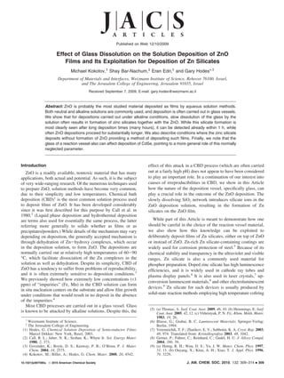
- 2. ARTICLES Kokotov et al. of ZnO and SiO2 powders.10 Alternative methods include RF magnetron sputtering,11 spray pyrolysis,12 sol-gel,13 polymer precursor,14 and various hydrothermal methods.15 All of these publications (except refs 11 and 13b,c, which describe film deposition) describe the preparation of Zn silicate powders. Experimental Section Substrate Activation. In most experiments, the films were deposited on soda-lime glass microscope slides. (Other substrates, including various plastics and titanium, were also used with results similar to those of glass.) The substrates were rinsed with Millipore deionized water (DW) in an ultrasonic bath. For the surface activation, the substrates were placed in glass Figure 1. SEM cross-section (a) and plane view (b) of a ZnO film deposited vials filled with 0.5 mM fresh KMnO4 solution.16 50 µL of at 92 °C for 40 min. n-butanol (as a reducing agent for the KMnO4) per 20 mL of the permanganate solution was added. The vials were closed and placed in a water bath at 85 °C for 20-30 min. Permanganate-treated substrates were extensively rinsed in DW (the vials containing the samples were filled with DW, which was then poured out, and this was repeated for a total of 10 rinses) and then sonicated 5-10 min in DW in an ultrasonic bath. The extensive rinsing is important to prevent nucleation of ZnO in the bulk of the deposition solution from Mn-containing particles detached from the treated substrate. The activation allows facile nucleation due to adsorption of Zn species on the hydrated Mn oxide nuclei. In the absence of activation, little or no deposit forms.16 ZnO Film Deposition. Deposition solutions were prepared using the following aqueous stock solutions: 1.0 M ZnSO4 (for some experiments, ZnAc2, ZnNO3, or ZnCl2 was used), 4.0 M ammonium hydroxide, and 50% (by volume) monoethanolamine (2-aminoet- hanol). The final deposition solution was prepared from the stock Figure 2. SEM images of ZnO films deposited at 90 °C for 1 h and kept solutions in 20 mL borosilicate glass vials (Wheaton liquid in the deposition solution at 75-80 °C for 5 days: (a,b) in a glass vial ((a) scintillation vials, part# 986541) or in polypropylene vials by dense ZnO film, (b) open morphology ZnO film from lower ammonia sequential addition to water of 1.0 mL of zinc salt, ∼1.5 mL of (complexant) concentration), (c) in a polypropylene vial. ammonia, and 2 mL of ethanolamine, giving the following final concentrations: 0.1 M Zn2+ (unless otherwise stated), 1.7 M (10% the substrate, the side chosen for characterization). The reaction v/v) ethanolamine, and ∼0.6 M NH3 (some results are shown for vial was closed and placed in a water bath at 75-95 °C. The films deposited using a lower ammonia concentration ∼0.5 M; this deposition time varied from 0.5 to ∼350 h. will be designated as “lower ammonia concentration”). The amount More details of the permanganate activation of the substrates of water was chosen so that the total volume of each solution was and of the ZnO deposition have been described previously.16 10 mL. The final pH was typically 11.0-11.2. For some experi- Film Characterization. Films deposited on the bottom side of ments, crushed glass, either from the vials or from the soda-lime the substrates were first visually inspected to monitor coating glass microscope slides, was added to some vials. Immediately after uniformity on a macro scale. Scanning electron microscopy was the solution preparation, the substrate was placed in the solution carried out with a high resolution “Ultra 55” FEG Zeiss scanning (slightly inclined from vertical to prevent particles, which might electron microscope (SEM). Elemental analysis mapping was done form in the solution from settling on the downward-facing side of by energy dispersive spectrometry (EDS) using an “OXFORD” detector in a SUPRA 55 VP FEG LEO SEM. Samples for cross- (10) (a) Schulman, J. H. J. Appl. Phys. 1946, 17, 902. (b) Brownlow, J. M.; section transition electron microscopy (TEM) were prepared using Chang, I. F. IEEE Trans. Electron DeVices 1983, ED-30, 479. (c) Guo, an FEI Helios dual beam focused ion beam (FIB) system. TEM Y.; Ohsato, H.; Kakimoto, K.-i. J. Eur. Ceram. Soc. 2006, 26, 1827. imaging and EDS analyses were done using a Philips CM120 TEM. (11) Minami, T.; Miyata, T.; Takata, S.; Fukuda, I. Jpn. J. Appl. Phys. 1991, 30, L117. X-ray diffraction (XRD) was carried out using a Rigaku RU300 (12) Kang, Y. C.; Park, S. B. Mater. Res. Bull. 2000, 35, 1143. rotating anode X-ray diffractometer. (13) (a) Morimo, R.; Matae, K. Mater. Res. Bull. 1989, 24, 175. (b) Ji, Z.; Kun, L.; Yongliang, S.; Zhizhen, Y. J. Cryst. Growth 2003, 255, 353. Results (c) Copeland, T. S.; Lee, B. I.; Qi, J.; Elrod, A. K. J. Lumin. 2002, As shown in our previous work,16 uniform ZnO films having 97, 168. (d) Lin, J.; Sanger, D. U.; Mennig, M.; Barner, K. Thin Solid Films 2000, 360, 39. typical morphology and crystal shapes shown in Figure 1 grow (14) Su, K.; Tilley, T. D.; Sailor, M. J. J. Am. Chem. Soc. 1996, 118, 3459. in about 40 min on substrates activated by permanganate. The (15) (a) Ahmadi, T. S.; Haase, M.; Weller, H. Mater. Res. Bull. 2000, 35, areal density of the ZnO crystals and the film morphology (ZnO 1869. (b) Lu, S. W.; Copeland, T.; Lee, B. I.; Tong, W.; Wagner, B. K.; Park, W.; Zhang, F. J. Phys. Chem. Solids 2001, 62, 777. (c) crystal size and aspect ratio and directionality/texture) can be Yoon, C.; Shinboo, K. J. Mater. Res. 2001, 16, 1210. (d) Wang, H.; tailored by varying activation conditions, the complexant:Zn Ma, Y.; Yi, G.; Chen, D. Mater. Chem. Phys. 2003, 82, 414. (e) Wang, concentration ratio, and by choice of the anion of the zinc salt. H.; Zhuang, J.; Peng, Q.; Li, Y. J. Solid State Chem. 2005, 178, 2332. (f) Xiong, L.; Shi, J.; Gu, J.; Shen, W.; Dong, X.; Chen, H.; Zhang, More recently, we found that increasing the pH of the deposition L.; Gao, J.; Ruan, M. Small 2005, 1, 1044. (g) Li, Q. H.; Komarneni, solution results in films with narrower ZnO crystals. S.; Roy, R. J. Mater. Sci. 1995, 30, 2358. (h) Wan, J.; Chen, X.; Wang, If, however, the deposition is continued for a much longer Z.; Mu, L.; Qian, Y. J. Cryst. Growth 2005, 280, 239. (i) Zeng, J. H.; time, the morphology of the films changes significantly (Figure Fu, H. L.; Lou, T. J.; Yu, Y.; Sun, Y. H.; Li, D. Y. Mater. Res. Bull. 2009, 44, 1106. 2a,b). The films become very fibrous, and individual rods appear (16) Kokotov, M.; Hodes, G. J. Mater. Chem. 2009, 19, 3847. to be composed of many fibers. We initially thought that this 310 J. AM. CHEM. SOC. 9 VOL. 132, NO. 1, 2010
- 3. Solution Deposition of ZnO Films ARTICLES Figure 3. SEM images of ZnO films deposited at 90 °C (a) in a polypropylene vial - 3 h deposition; (b) in a glass vial - 1 h deposition; and (c) in a glass vial - 3 h deposition. The insets show lower magnification images. All three samples were placed together on one SEM sample holder, and all images were taken using identical SEM operating parameters, including contrast and brightness. fibrous ones, is found even under standard pH conditions (Figure 6b,c). Such dual morphology behavior of Zn silicate is described in the hydrothermal literature, showing a greater tendency for spherical morphology at lower pH or at lower ammonia concentration,15a,g,i the same as we find for our films. This dual morphology behavior of zinc silicate was also found in synthesis from organic solutions.18 SEM backscattered images of such films clearly show that Figure 4. SEM images of a ZnO film deposited in a glass vial at 90 °C the overlayer on the ZnO has a lower average atomic number for 4 h and kept in the deposition solution at 80 °C for 4 h. (a) Plan view than that of the ZnO itself but higher that that of the glass and (b) cross-section view. substrate (Figure 7b together with the secondary electron image in Figure 7a). A cross-section EDS line scan through the film fibrous structure was due to etching of the ZnO by the alkaline thickness (Figure 7c) shows that the overlayer consists of Si, solution after the Zn2+ concentration in the deposition bath Zn, and O in contrast to only Zn and O in the underlying film. became low enough. However, under identical deposition It also shows that there is relatively more O and less Zn in the conditions, when plastic vials were used in place of glass ones, overlayer than in the ZnO underlayer. Cross-section TEM this fibrous morphology did not occur (Figure 2c).17 imaging of the film (Figure 7d-h) reveals a nanogranular A change in surface appearance of the initially deposited structure (no crystal plane fringes were observed in the smooth ZnO rods is already seen by SEM imaging after 1 h of nanograins) of the overlayer (Figure 7f) and the single crystal deposition. Figure 3b shows the formation of white “spots” some nature of the ZnO rods (Figure 7g, which shows a smooth, nanometers in size on the top of a ZnO rod grown for 1 h in a featureless region of a ZnO crystal, and Figure 7h, a higher glass vial, suggesting formation of a different phase. The magnification image showing lattice fringes). The selected area difference in contrast between the white spots and the darker electron diffraction patterns of the overlayer are very weak and ZnO is due to electric potential difference between the spots broad but seem to match the powder pattern of ZnO. This (different charging of the spots as compared to that of the ZnO; indicates inclusions of some amount of ZnO nanocrystals in the in-lens secondary electron detector used is particularly the apparently amorphous silicate phase. EDS/REM analysis sensitive to charging effects). The growth of these “spots” of the overlayer gave an atomic % composition of: O ∼56%; continues until, after 3 h of growth, a continuous layer of this Si ∼12%; Zn ∼32%. In most cases, XRD of these films does phase is formed on the ZnO (Figure 3c). For films grown under not reveal any additional phase besides the ZnO. However, in identical conditions but in a plastic vial, no sign of this growth some samples, additional weak broad peaks and widening of occurs (Figure 3a). After 4 h, growth of a separate layer on the the ZnO (100) peak were observed (Figure 8). The broad peaks sides of the ZnO rods, as well as on their tops, can be clearly can be best matched to a Na2Zn(Si2O6) phase.19 No correlation seen (Figure 4). The nature of the growth of this fibrous layer was found between deposition condition or film morphology depends on the morphology of the ZnO rods. Under conditions and appearance of these peaks. Annealing of the films at where open (loosely packed) ZnO rods form (in this case, by temperatures up to 500 °C (limited by the glass substrate) did using a lower ammonia concentration), the layer grows on not affect the XRD pattern. Combining all of the above results, individual ZnO crystals (Figures 5a-c and 2b). For closer- together with the general observation from the literature that packed ZnO rods, this overlayer coalesces to form a dense the most usual phase for hydrothermally grown zinc silicate is coating on the ZnO film (Figures 5d-f and 2a). This fibrous the willemite Zn2SiO4 phase, we consider that the most likely growth resembles the morphology of particles of Zn silicate composition for this overlayer is the willemite phase with some powders obtained by hydrothermal methods (but at higher inclusions of nanocrystalline ZnO and maybe also some temperature than our deposition conditions) as described in refs sodium-zinc silicate phase. (Na usually is not reliably detected 15d,h,f,i. The maximum thickness of the overlayer is achieved by EDS due to its tendency to evaporate under the electron after about 3 days, depending on the solution temperature. A more spherical morphology of this overgrowth is obtained at slightly lower pH (10.8 instead of 11.0-11.2), as shown in (18) Lou, T. J.; Zeng, J. H.; Lou, X. D.; Fu, H. L.; Wang, Y. F.; Ma, R. L.; Tong, L. J.; Chen, Y. L. J. Colloid Interface Sci. 2007, 314, Figure 6a. On occasion, such a morphology, or a morphology 510. intermediate between that in Figure 6a and the more typical (19) There are at least dozens of alkali metal zinc silicate phases, each with a large number of peaks in the XRD pattern. Also, most well- defined XRD patterns in the literature of zinc silicate compounds in (17) We note that most of the results shown in this Article were obtained general are obtained after high-temperature annealing. A positive using ZnSO4, but control experiments employing other zinc salts identification of the measured XRD patterns in our case is therefore showed similar behavior, although with different rod diameters less than reliable. The exact composition and phase is not of great obtained depending on the anion of the Zn salt.16 relevance for this Article. J. AM. CHEM. SOC. 9 VOL. 132, NO. 1, 2010 311
- 4. ARTICLES Kokotov et al. Figure 5. SEM cross-section views of two series of ZnO film depositions. (a-c) Films deposited from bath containing lower concentration of NH3, less closely packed and less aligned ZnO rods after 24, 140, and 270 h deposition respectively; (d-f) normal concentration of NH3, more closely packed and more vertically aligned ZnO rods after 13, 63, and 120 h deposition, respectively. Note the magnification is not identical for the two series. Figure 6. SEM images of depositions showing (a) a repeatable spherical morphology at lower pH - acid added. Occasional spherical morphology obtained using (b) low ammonia concentration and (c) normal ammonia concentration. Figure 7. (a) Secondary electrons and (b) backscattered electron cross-section SEM images of dense ZnO film with thick overlayer. (c) SEM EDS line scan map across the film cross-section. (d-h) Cross-section TEM images of a similar film. (d) Upper parts of the ZnO rods covered with an overlayer (the dark gray and the black layers on top of the bright gray overlayer are metal films deposited for FIB lamella cutting). (e) Zoom-in of a section of (d). (f) Zoom-in of the overlayer. (g) Zoom-in of the ZnO crystal. (h) High magnification lattice image of the ZnO crystal. beam.) If willemite and ZnO are indeed the two main phases, were added to the deposition solution in plastic vials. The film the semiquantitative TEM EDS results above are consistent with morphology in these cases was similar to that obtained using an average overlayer atomic composition corresponding to a glass vials. This provides additional proof that formation of the calculated volume ratio of 85% amorphous Zn2SiO4 and 15% Si-containing overlayer is due to dissolution of glass. A larger nanocrystalline ZnO. amount of crushed glass or finer glass pieces added to a As control experiments, pieces of broken glass (either from deposition solution result in faster formation of the crust soda-lime glass microscope slides or borosilicate glass vials) overlayer, as expected. However, if sodium silicate is added to 312 J. AM. CHEM. SOC. 9 VOL. 132, NO. 1, 2010
- 5. Solution Deposition of ZnO Films ARTICLES Figure 10. XRD pattern of an annealed (500 °C) film deposited using a Figure 8. XRD pattern of ZnO film covered by an overlayer as in Figure low concentration (25 mM) of zinc, other conditions as standard. The vertical 5e. All sharp peaks belong to ZnO. The vertical lines show the database lines show the database pattern of the Zn2SiO4 (willemite, zinc silicate) pattern of the Na2Zn(Si2O6) phase (PDF#01-072-0741). phase (PDF#00-037-1485). the deposition solution at the start of deposition, a precipitate We can reasonably assume that the silicate overlayer forms when forms immediately in the solution, and very little film formation the Zn2+ concentration drops below the concentration at which occurs. Thus, slow release of silicate into the solution is ZnO can continue to grow and an equilibrium is established necessary for film formation. between dissolution and growth of ZnO. If this assumption is It might be asked why the glass substrate itself does not true, then by starting with a low enough Zn2+ concentration (or supply silicate ions to the deposition solution. ZnO deposition high enough complex:Zn ratio), we should be able to obtain a by CBD normally requires activation of the substrate to allow predominantly or even solely Zn silicate film. Figure 9 shows ZnO nucleation. While the glass substrates are activated (by SEM images of such films using 25% of the original Zn permanganate treatment in this work), the vessel is not. Thus, concentration (25 mM instead of 100 mM), all other components the ZnO layer, which forms only on the activated substrate, of the solution kept unchanged. Thin, apparently amorphous or protects it against dissolution. We note that, for a long period of time, we were not aware very small crystal films were observed on the glass substrates of the silicate formation and thought that it was ZnO possessing using ZnCl2 (or ZnSO4) (Figure 9a,b). Extremely strong a novel morphology. It was only after carrying out cross-section adhesion of the film to the substrate is indicated by the backscattered SEM (of particularly long depositions) that we continuous crack lines, from the sample fracture, across the realized there was a difference in composition between the ZnO interface (Figure 9b). No XRD pattern was found from these and what we eventually realized was silicate and that some as-deposited films. After being annealed at 500 °C for 1 h in silicate already started to form even after short depositions, air, two types of crystals could be seen in the SEM images: although this was not readily visible in its early stages in SEM large ill-defined crystals inside the film (Figure 9d,f) and smaller imaging. Also, as noted above, the silicate would not be seen faceted crystals embedded into the film surface (Figure 9e) (no by XRD because no (or virtually no) XRD pattern is seen, even atomic weight contrast is seen by backscattered imaging in either after thick layers of silicate had formed. annealed or as-deposited films (Figure 9c,f)). Longer annealing Using our deposition conditions, ZnO film growth is a fast at the same temperature did not change this picture. Weak XRD process; it takes about 40 min until the ZnO film reaches its peaks indicating the presence of Zn2SiO4 (willemite zinc silicate) maximal thickness (this is faster than most other ZnO baths). appeared after annealing (Figure 10).19 Figure 9. SEM secondary electron (a,b,d,e) and backscattered (c,f) images of a silicate film deposited using a low concentration of zinc (25 mM ZnCl2). As deposited (a,b,c), annealed (d,e,f). Part (e) shows a zoomed-in region of the surface. J. AM. CHEM. SOC. 9 VOL. 132, NO. 1, 2010 313
- 6. ARTICLES Kokotov et al. Finally, in view of our interest in nanoporous solar cells, we containing nitrilotriacetic acid as a complexing agent,21 proceeds fabricated ZnO/CdSe/CuSCN solar cells using CBD ZnO on much faster in a borosilicate vial than in a plastic one. SnO2-conducting glass.20 Three cells were made using ZnO Furthermore, if some pieces of soda-lime glass are introduced deposited in glass vials and three cells using ZnO deposited into such a bath, a substantial amount of Si is incorporated into under identical conditions but in plastic vials. In all cases, the the resulting films. The possibility of formation of silicates has cells made in plastic vials gave open circuit voltages that were to be taken into account because they can dramatically alter significantly higher (by g70 mV) than the control cells made chemical, structural, and electronic properties of the deposited using ZnO deposited in glass vials (the other cell parameters films. In preliminary experiments, the open circuit voltage of did not vary in any systematic way between the two types of CdSe-sensitized ZnO nanoporous solar cells is increased ZnO). While preliminary, these experiments emphasize the considerably if the CBD ZnO is grown in a plastic vial as importance of the nature of the reaction vessel in ZnO compared to a glass one. deposition. We also present preliminary results that exploit this phenom- Conclusions enon to deliberately grow Zn silicate films, an important Chemical bath deposition (CBD) of ZnO from alkaline compound for luminescence and anticorrosion applications. In solution in a glass reaction vessel gives initially ZnO, but an this case, a low starting concentration of Zn in the deposition alkali metal Zn silicate phase forms as an overlayer on the ZnO solution prevents growth of ZnO, and only the silicate is formed as the Zn concentration in the bath decreases with time and as a very adherent film on glass substrates. Silicates of Zn cannot this overlayer becomes thicker with increasing growth time. This be grown simply by adding alkali metal silicate solution to the phase forms due to slow etching of the glass vessel (both deposition bath as immediate precipitation occurs; the slow borosilicate and soda-lime glass behave similarly) at the pH of release of the soluble silicate is essential for this deposition. the solution (ca. 11). This etching gradually releases silicate The source of the Si can be either the glass vessel itself or ions to the solution, which react to give the silicate. Using plastic deliberately-added glass. reaction vessels, only ZnO is formed regardless of the deposition time. While etching of glass in strongly alkaline solution is well- Acknowledgment. This work was supported by the US-Israel known, these results show that even under relatively mild Binational Science Foundation and the Alternative Energy Research alkaline condition, glass etching occurs and, more importantly, Initiative (AERI). We thank Dr. Yishay Feldman for help with XRD can completely change the nature of the deposit. Recently, we analysis, Dr. Palle von Huth for help with FIB sample cross- have noted that the influence of glass is not limited to ZnO sectioning, and Dr. Ronit Popovitz-Biro for help with TEM imaging. depositions but that it is more general. Ion-by-ion deposition The electron microscopy studies were conducted at the Irving and of CdSe, carried out under alkaline conditions from solutions Cherna Moskowitz Center for Nano and Bio-Nano Imaging at the Weizmann Institute of Science. We acknowledge the Harold (20) Levy-Clement, C.; Tena-Zaera, R.; Ryan, M. A.; Katty, A.; Hodes, Perlman family’s historic generosity. G. AdV. Mater. 2005, 17, 1512. (21) Gorer, S.; Hodes, G. J. Phys. Chem. 1994, 98, 5338. JA907580U 314 J. AM. CHEM. SOC. 9 VOL. 132, NO. 1, 2010