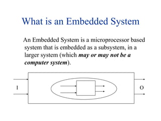
1. What is an Embedded System An Embedded System is a microprocessor based system that is embedded as a subsystem, in a larger system (which may or may not be a computer system). O I
3. Design challenge optimizing design metrics Obvious design goal: Construct an implementation with desired functionality Key design challenge: Simultaneously optimize numerous design metrics Design metric A measurable feature of a system’s implementation Optimizing design metrics is a key challenge
4. Common metrics Unit cost: the monetary cost of manufacturing each copy of the system, excluding NRE cost NRE cost (Non-Recurring Engineering cost): The one-time monetary cost of designing the system Size: the physical space required by the system Performance: the execution time or throughput of the system Power: the amount of power consumed by the system Flexibility: the ability to change the functionality of the system without incurring heavy NRE cost Design challenge optimizing design metrics
5. IC technology Three types of IC technologies Full-custom/VLSI Semi-custom ASIC (gate array and standard cell) PLD (Programmable Logic Device)
6. Full-custom/VLSI All layers are optimized for an embedded system’s particular digital implementation Placing transistors Sizing transistors Routing wires Benefits Excellent performance, small size, low power Drawbacks High NRE cost (e.g., $300k), long time-to-market
7. Semi-custom Lower layers are fully or partially built Designers are left with routing of wires and maybe placing some blocks Benefits Good performance, good size, less NRE cost than a full-custom implementation (perhaps $10k to $100k) Drawbacks Still require weeks to months to develop
8. PLD (Programmable Logic Device) All layers already exist Designers can purchase an IC Connections on the IC are either created or destroyed to implement desired functionality Field-Programmable Gate Array (FPGA) very popular Benefits Low NRE costs, almost instant IC availability Drawbacks Bigger, expensive (perhaps $30 per unit), power hungry, slower
9. FPGA OTP One time Programmed MTP Multi-Time Programmed
13. CMOS transistor on silicon source gate Conducts if gate=1 drain 1 gate oxide IC package IC source channel drain Silicon substrate Transistor The basic electrical component in digital systems Acts as an on/off switch Voltage at “gate” controls whether current flows from source to drain Don’t confuse this “gate” with a logic gate
14. CMOS transistor implementations source source gate Conducts if gate=0 gate Conducts if gate=1 drain drain pMOS nMOS 1 1 1 x x y x F = x' y F = (xy)' x F = (x+y)' y 0 x y 0 0 NOR gate inverter NAND gate Complementary Metal Oxide Semiconductor We refer to logic levels Typically 0 is 0V, 1 is 5V Two basic CMOS types nMOS conducts if gate=1 pMOS conducts if gate=0 Hence “complementary” Basic gates Inverter, NAND, NOR
15.
16. Basic logic gates x x F F x x F x F y x F x y x y x y x y x y x y F F F F F F y 0 0 0 1 F y 0 0 0 0 0 0 0 0 0 0 0 1 0 0 1 0 0 1 1 1 1 0 0 1 0 0 1 1 0 1 1 0 1 0 0 1 1 0 1 0 1 0 0 1 0 1 1 0 1 1 0 0 1 0 1 1 0 0 1 1 1 1 1 1 1 1 0 1 1 1 1 1 0 1 1 0 x x x F x F F F y y y F = x y XNOR F = x y AND F = x y XOR F = x Driver F = x + y OR F = (x y)’ NAND F = x’ Inverter F = (x+y)’ NOR
18. What is VHDL? A very verbose, complex, and powerful language for design, simulation, verification and synthesis of digital systems Supports many levels of abstraction, ranging from algorithm level to gate level Can model concurrentand sequential behaviors of digital systems Supports design hierarchy as interconnections of components Can explicitly model the timing of digital systems
19. What is VHDL? Just as high-level programming languages allow complex design concepts to be expressed as computer programs, VHDL allows the behavior of complex electronic circuits to be captured into a design system for automatic circuit synthesis or for system simulation. Like Pascal, C and C++, VHDL includes features useful for structured design techniques, and offers a rich set of control and data representation features. Unlike these other programming languages, VHDL provides features allowing concurrent events to be described. This is important because the hardware described using VHDL is inherently concurrent in its operation.
20. History of VHDL 1980: The USA department of defense (DOD) wanted to make circuit design self documenting. 1983: The development of VHDL began with a joint effort by IBM, Texas Instruments and Inter-metrics. 1987: The institute of Electrical and Electronics Engineers (IEEE) was presented with a proposal to standardize the language. The resulting standard, IEEE 1076-1987, is the basis for virtually every simulation and synthesis product sold today. 1993: The VHDL language was revised to IEEE 1076-1993 1996: A VHDL package for use with synthesis tools become part of the IEEE 1076 standard, specifically it is 1076.3. This greatly improved the portability of designs between different synthesis vendor tools. Another part of the standard, IEEE 1076.4 (VITAL), has been completed and sets a new standard for modeling ASIC and FPGA libraries in VHDL. This made life considerably easier for ASIC, FPGA and EDA tools vendors.
21. Verilog Verilog was introduced first before VHDL, thus established itself as the de facto standard language for ASIC simulation libraries; Verilog has some advantage in availability of simulation models. Another important feature that is defined in Verilog is a programming language interface PLI. The PLI makes it possible for simluation model writers to go outside of Verilog when necessary to create faster simulation models, or to create functions (using the C language) that would be difficult or inefficient to implement directly in Verilog.
22. History of Verilog 1981: A CAE (Computer Aided Engineering) software company called Gateway Design Automation was founded by PrabhuGoel. 1983: Gateway released the Verilog hardware description language known as “Verilog HDL” together with a Verilog simulator. 1985: The language and simulator has enhanced; the new version of the simulator was called “Verilog-XL”. 1987: Verilog-XL was becoming very popular and has been used by many ASIC vendors. Another start-up company, Synopsys, began to use the proprietary Verilog behavioral language as an input to their synthesis product. 1989: Cadence bought Gateway. 1995: The Verilog language was reviewed and adopted by IEEE as IEEE standard 1364.
23. VHDL VHDL is a programming language that allows one to model and develop complex digital systems in a dynamic environment. 3 ways to DO IT -- the VHDL way Geometric Functional (Behavioral) Structural
24. Let’s Write a VHDL Model ... ENTITY full_adder IS PORT ( A, B, Cin : IN BIT; Sum, Cout : OUT BIT ); END full_adder; Can we build the Full Adder’s architecture using these gates?
25. Full Adder Architecture for Cout (I.e. Carry Out): Cin (I.e. Carry In) A B 0 1 0 0 0 0 0 1 0 1 1 1 1 1 1 0 0 1 for Sum: Cin (I.e. Carry In): SUM A B 0 1 CIN 0 0 0 1 0 1 1 0 A COUT 1 1 0 1 1 0 1 0 B
26. Two Full Adder Processes Summation: PROCESS( A, B, Cin) BEGIN Sum <= A XOR B XOR Cin; END PROCESS Summation; Carry: PROCESS( A, B, Cin) BEGIN Cout <= (A AND B) OR (A AND Cin) OR (B AND Cin); END PROCESS Carry;
27. Full Adder CIN entityFull_Adderis port (A, B,CIN: in BIT; SUM, COUT: out BIT); endFull_Adder; architectureFull_AdderofFull_Adderis begin SUM <= A xor B xor CIN after 15ns; COUT <= (A and B) or (B and CIN) or (CIN and A) after 10ns; endFull_Adder; SUM Full_Adder A B COUT
28. Basic Design Methodology Requirements Simulate RTL Model Synthesize Gate-levelModel Simulate Test Bench ASIC or FPGA Place & Route TimingModel Simulate
29. Design Flow Reading preliminary Specs. From Customer Define the full definition of the problem Detailed specification and architecture of the design. Detailed test structure for Specs. And Architecture. Design S.W. to prove the idea “C, Matlab, …” (Emulation) Top-Down Design “HDL, FSM, Flowchart,…” Functional simulation Logic synthesis: analysis Place and route Real timing optimization Download design on the FPGA Hardware testing.