Tutorial part 2 Create a project and start drawing schematics
•
0 gefällt mir•704 views

CadSoft hat sich auf die Entwicklung der renommierten PCB Design Software EAGLE spezialisiert. EAGLE wird in unterschiedlichen Editionen angeboten und verfügt über einen Schaltplan-Editor, Layout-Editor sowie Autorouter.

Empfohlen
Weitere ähnliche Inhalte
Was ist angesagt?
Was ist angesagt? (20)
Ähnlich wie Tutorial part 2 Create a project and start drawing schematics
Ähnlich wie Tutorial part 2 Create a project and start drawing schematics (20)
Kürzlich hochgeladen
Kürzlich hochgeladen (20)
Tutorial part 2 Create a project and start drawing schematics
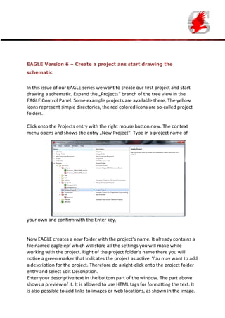
- 1. EAGLE Version 6 – Create a project ans start drawing the schematic In this issue of our EAGLE series we want to create our first project and start drawing a schematic. Expand the „Projects“ branch of the tree view in the EAGLE Control Panel. Some example projects are available there. The yellow icons represent simple directories, the red colored icons are so-called project folders. Click onto the Projects entry with the right mouse button now. The context menu opens and shows the entry „New Project“. Type in a project name of your own and confirm with the Enter key. Now EAGLE creates a new folder with the project's name. It already contains a file named eagle.epf which will store all the settings you will make while working with the project. Right of the project folder's name there you will notice a green marker that indicates the project as active. You may want to add a description for the project. Therefore do a right-click onto the project folder entry and select Edit Description. Enter your descriptive text in the bottom part of the window. The part above shows a preview of it. It is allowed to use HTML tags for formatting the text. It is also possible to add links to images or web locations, as shown in the image.
- 2. The supported HTML tags are described in the EAGLE help function (Help menu, General help, Search for: HTML). Next step is to create a new schematic. Therefore do a right mouse click onto the project entry in the treeview and select New.../Schematic. The Schematic Editor window appears. Our first action will be to place a drawing frame, which can be found in Frames.lbr. Use the ADD icon in order to place components or frames in the schematic. The ADD icon can be found on the left side in the icon toolbar. Click onto the icon and a window with all the libraries available opens. Scroll down the list and look for frames. Expand the frames entry and choose one of the frames. After OK the frame can be placed in the schematic. Fix it with a mouse click at the coordinate’s origin. Now go on and try adding further parts. Rcl.lbr, for example, contains resistors, capacitors and inductors. Try out the
- 3. search function as well. Next time I will tell you more about drawing the schematic.