Mechanical report
•Download as DOCX, PDF•
1 like•227 views

This document describes a finite element analysis project that models a trapezoidal concrete slab. The model includes the slab geometry, mesh, material properties, loads applied, and results of the static structural analysis. The analysis found a maximum total deformation of 3.0713e-002 mm, maximum equivalent elastic strain of 5.2723e-005 mm/mm, and maximum equivalent stress of 1.5798 MPa in the slab under a 5000 N fixed support force.

Recommended
Recommended
More Related Content
Viewers also liked
Viewers also liked (19)
Similar to Mechanical report
Similar to Mechanical report (20)
Recently uploaded
Recently uploaded (20)
Mechanical report
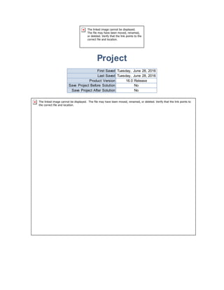
- 1. Project First Saved Tuesday, June 28, 2016 Last Saved Tuesday, June 28, 2016 Product Version 16.0 Release Save Project Before Solution No Save Project After Solution No
- 2. Contents Units Model (A4) o Geometry Solid o Coordinate Systems o Mesh Automatic Method o Static Structural (A5) Analysis Settings Loads Solution (A6) Solution Information Results Force Reaction Material Data o Concrete Units TABLE 1 Unit System Metric (mm, kg, N, s, mV, mA) Degrees rad/s Celsius Angle Degrees Rotational Velocity rad/s Temperature Celsius Model (A4) Geometry TABLE 2 Model (A4) > Geometry Object Name Geometry State Fully Defined Definition Source D:ANSYSPLACA TRAPEZOIDALPlaca Trazapzoidal_filesdp0SYSDMSYS.agdb Type DesignModeler Length Unit Meters Element Control Program Controlled Display Style Body Color Bounding Box Length X 700. mm Length Y 10. mm Length Z 500. mm Properties
- 3. Volume 2.8e+006 mm³ Mass 6.44 kg Scale Factor Value 1. Statistics Bodies 1 Active Bodies 1 Nodes 360 Elements 153 Mesh Metric None Basic Geometry Options Parameters Yes Parameter Key DS Attributes No Named Selections No Material Properties No Advanced Geometry Options Use Associativity Yes Coordinate Systems No Reader Mode Saves Updated File No Use Instances Yes Smart CAD Update No Compare Parts On Update No Attach File Via Temp File Yes Temporary Directory C:UsersTOSHIBAAppDataLocalTemp Analysis Type 3-D Decompose Disjoint Geometry Yes Enclosure and Symmetry Processing Yes TABLE 3 Model (A4) > Geometry > Parts Object Name Solid State Meshed Graphics Properties Visible Yes Transparency 1 Definition Suppressed No Stiffness Behavior Flexible Coordinate System Default Coordinate System Reference Temperature By Environment Material Assignment Concrete Nonlinear Effects Yes Thermal Strain Effects Yes Bounding Box Length X 700. mm
- 4. Length Y 10. mm Length Z 500. mm Properties Volume 2.8e+006 mm³ Mass 6.44 kg Centroid X 320.83 mm Centroid Y -5. mm Centroid Z 250. mm Moment of Inertia Ip1 91287 kg·mm² Moment of Inertia Ip2 3.4872e+005 kg·mm² Moment of Inertia Ip3 2.5754e+005 kg·mm² Statistics Nodes 360 Elements 153 Mesh Metric None Coordinate Systems TABLE 4 Model (A4) > Coordinate Systems > Coordinate System Object Name Global Coordinate System State Fully Defined Definition Type Cartesian Coordinate System ID 0. Origin Origin X 0. mm Origin Y 0. mm Origin Z 0. mm Directional Vectors X Axis Data [ 1. 0. 0. ] Y Axis Data [ 0. 1. 0. ] Z Axis Data [ 0. 0. 1. ] Mesh TABLE 5 Model (A4) > Mesh Object Name Mesh State Solved Display Display Style Body Color Defaults Physics Preference Mechanical Relevance 0 Sizing Use Advanced Size Function Off Relevance Center Coarse
- 5. Element Size Default Initial Size Seed Active Assembly Smoothing Medium Transition Fast Span Angle Center Coarse Minimum Edge Length 10.0 mm Inflation Use Automatic Inflation None Inflation Option Smooth Transition Transition Ratio 0.272 Maximum Layers 5 Growth Rate 1.2 Inflation Algorithm Pre View Advanced Options No Patch Conforming Options Triangle Surface Mesher Program Controlled Patch Independent Options Topology Checking No Advanced Number of CPUs for Parallel Part Meshing Program Controlled Shape Checking Standard Mechanical Element Midside Nodes Program Controlled Straight Sided Elements No Number of Retries Default (4) Extra Retries For Assembly Yes Rigid Body Behavior Dimensionally Reduced Mesh Morphing Disabled Defeaturing Pinch Tolerance Please Define Generate Pinch on Refresh No Automatic Mesh Based Defeaturing On Defeaturing Tolerance Default Statistics Nodes 360 Elements 153 Mesh Metric None TABLE 6 Model (A4) > Mesh > Mesh Controls Object Name Automatic Method State Fully Defined Scope Scoping Method Geometry Selection Geometry 1 Body Definition Suppressed No Method Automatic Element Midside Nodes Dropped
- 6. Static Structural (A5) TABLE 7 Model (A4) > Analysis Object Name Static Structural (A5) State Solved Definition Physics Type Structural Analysis Type Static Structural Solver Target Mechanical APDL Options Environment Temperature 22. °C Generate Input Only No TABLE 8 Model (A4) > Static Structural (A5) > Analysis Settings Object Name Analysis Settings State Fully Defined Step Controls Number Of Steps 1. Current Step Number 1. Step End Time 1. s Auto Time Stepping Program Controlled Solver Controls Solver Type Program Controlled Weak Springs Program Controlled Solver Pivot Checking Program Controlled Large Deflection Off Inertia Relief Off Restart Controls Generate Restart Points Program Controlled Retain Files After Full Solve No Nonlinear Controls Newton-Raphson Option Program Controlled Force Convergence Program Controlled Moment Convergence Program Controlled Displacement Convergence Program Controlled Rotation Convergence Program Controlled Line Search Program Controlled Stabilization Off Output Controls Stress Yes Strain Yes Nodal Forces No Contact Miscellaneous No General Miscellaneous No Store Results At All Time Points
- 7. Analysis Data Management Solver Files Directory D:ANSYSPLACA TRAPEZOIDALPlaca Trazapzoidal_filesdp0SYSMECH Future Analysis None Scratch Solver Files Directory Save MAPDL db No Delete Unneeded Files Yes Nonlinear Solution No Solver Units Active System Solver Unit System nmm TABLE 9 Model (A4) > Static Structural (A5) > Loads Object Name Fixed Support Force State Fully Defined Scope Scoping Method Geometry Selection Geometry 1 Face Definition Type Fixed Support Force Suppressed No Define By Components Coordinate System Global Coordinate System X Component 5000. N (ramped) Y Component 0. N (ramped) Z Component 0. N (ramped) FIGURE 1 Model (A4) > Static Structural (A5) > Force
- 8. Solution (A6) TABLE 10 Model (A4) > Static Structural (A5) > Solution Object Name Solution (A6) State Solved Adaptive Mesh Refinement Max Refinement Loops 1. Refinement Depth 2. Information Status Done Post Processing Calculate Beam Section Results No TABLE 11 Model (A4) > Static Structural (A5) > Solution (A6) > Solution Information Object Name Solution Information State Solved Solution Information Solution Output Solver Output Newton-Raphson Residuals 0 Update Interval 2.5 s Display Points All FE Connection Visibility Activate Visibility Yes
- 9. Display All FE Connectors Draw Connections Attached To All Nodes Line Color Connection Type Visible on Results No Line Thickness Single Display Type Lines TABLE 12 Model (A4) > Static Structural (A5) > Solution (A6) > Results Object Name Total Deformation Equivalent Elastic Strain Equivalent Stress State Solved Scope Scoping Method Geometry Selection Geometry All Bodies Definition Type Total Deformation Equivalent Elastic Strain Equivalent (von-Mises) Stress By Time Display Time Last Calculate Time History Yes Identifier Suppressed No Results Minimum 0. mm 2.6419e-005 mm/mm 0.79138 MPa Maximum 3.0713e-002 mm 5.2723e-005 mm/mm 1.5798 MPa Information Time 1. s Load Step 1 Substep 1 Iteration Number 1 Integration Point Results Display Option Averaged Average Across Bodies No FIGURE 2 Model (A4) > Static Structural (A5) > Solution (A6) > Total Deformation
- 10. TABLE 13 Model (A4) > Static Structural (A5) > Solution (A6) > Total Deformation Time [s] Minimum [mm] Maximum [mm] 1. 0. 3.0713e-002 FIGURE 3 Model (A4) > Static Structural (A5) > Solution (A6) > Equivalent Elastic Strain
- 11. TABLE 14 Model (A4) > Static Structural (A5) > Solution (A6) > Equivalent Elastic Strain Time [s] Minimum [mm/mm] Maximum [mm/mm] 1. 2.6419e-005 5.2723e-005 FIGURE 4 Model (A4) > Static Structural (A5) > Solution (A6) > Equivalent Stress
- 12. TABLE 15 Model (A4) > Static Structural (A5) > Solution (A6) > Equivalent Stress Time [s] Minimum [MPa] Maximum [MPa] 1. 0.79138 1.5798 TABLE 16 Model (A4) > Static Structural (A5) > Solution (A6) > Probes Object Name Force Reaction State Solved Definition Type Force Reaction Location Method Boundary Condition Boundary Condition Fixed Support Orientation Global Coordinate System Suppressed No Options Result Selection X Axis Display Time End Time Results X Axis -5000. N Maximum Value Over Time X Axis -5000. N Minimum Value Over Time X Axis -5000. N Information
- 13. Time 1. s Load Step 1 Substep 1 Iteration Number 1 FIGURE 5 Model (A4) > Static Structural (A5) > Solution (A6) > Force Reaction TABLE 17 Model (A4) > Static Structural (A5) > Solution (A6) > Force Reaction Time [s] Force Reaction (X) [N] 1. -5000. Material Data Concrete TABLE 18 Concrete > Constants Density 2.3e-006 kg mm^-3 Coefficient of Thermal Expansion 1.4e-005 C^-1 Specific Heat 7.8e+005 mJ kg^-1 C^-1 Thermal Conductivity 7.2e-004 W mm^-1 C^-1 TABLE 19 Concrete > Compressive Ultimate Strength
- 14. Compressive Ultimate Strength MPa 41 TABLE 20 Concrete > Compressive Yield Strength Compressive Yield Strength MPa 0 TABLE 21 Concrete > Tensile Yield Strength Tensile Yield Strength MPa 0 TABLE 22 Concrete > Tensile Ultimate Strength Tensile Ultimate Strength MPa 5 TABLE 23 Concrete > Isotropic Secant Coefficient of Thermal Expansion Reference Temperature C 22 TABLE 24 Concrete > Isotropic Elasticity Temperature C Young's Modulus MPa Poisson's Ratio Bulk Modulus MPa Shear Modulus MPa 30000 0.18 15625 12712