1. lua Rd
Moana
Ka`a
20 feet from wetland
hum
limit to edge of
anu
retaining wall
St
Waiau Wetland
New sidewalk
Kamehameha Hwy
s
4 culverts under highway
Spring
draining into Waiau Springs
Waiau
LEGEND
The Project
Wetland Limit
Columns Near Streams PEARL
HARBOR
0 500 1000
Feet
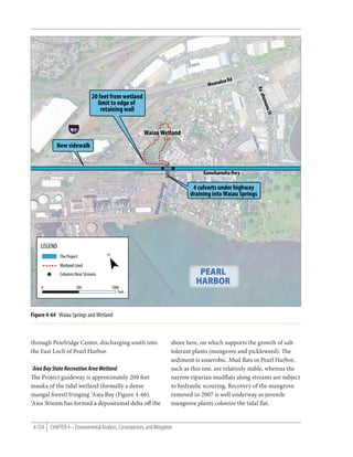
Figure 4-64 Waiau Springs and Wetland
through Pearlridge Center, discharging south into shore here, on which supports the growth of salt-
the East Loch of Pearl Harbor. tolerant plants (mangrove and pickleweed). e
sediment is anaerobic. Mud ats in Pearl Harbor,
`Aiea Bay State Recreation Area Wetland such as this one, are relatively stable, whereas the
e Project guideway is approximately 200 feet narrow riparian mud ats along streams are subject
mauka of the tidal wetland (formally a dense to hydraulic scouring. Recovery of the mangrove
mangal forest) fringing ‘Aiea Bay (Figure 4-66). removed in 2007 is well underway as juvenile
‘Aiea Stream has formed a depositional delta o the mangrove plants colonize the tidal at.
4-154 CHAPTER 4 – Environmental Analysis, Consequences, and Mitigation
2. i St
noh
Kao
20 feet from wetland
limit to edge of
Kam retaining wall
eha
meh
a Hwy
Sumida Watercress Farm ngs
ao Spri i St
K alau Pali
Mom
Wetland extends
Pearlridge beyond limit
New sidewalk
ngs
am
Spri
ao Stre
uao
Kala
K alau
am
Stre
uao Kam
Kala eham
eha
`Aiea Kai Pl Hwy
LEGEND
The Project
Fixed Guideway Station
Wetland Limit
0 250 500
Feet
Figure 4-65 Sumida Watercress Farm Wetland
Aolele Ditch of the three wetlands connects to the tidal reach of
Aolele Ditch is a man-made drainage feature Aolele Ditch and harbors top minnows (poeciliids)
constructed to drain stormwater to Ke‘ehi Lagoon and American cray sh, suggesting a permanent
from the northeastern portion of Honolulu Inter- fresh or slightly brackish wetland that has devel-
national Airport and an adjacent light industrial oped on a thin layer of sediment over the concrete
area. e lower end of the ditch is tidal. However, channel bed in this segment.
the part of the ditch crossed by the guideway is
an intermittently owing (non-RPW), unlined, Marine Waters
open ditch fed by several small drains from the e large coastal surface water bodies within
light industrial area mauka. ese drains provide or adjacent to the study corridor are listed in
su cient freshwater to establish three small semi- Table 4-28 and illustrated in Figure 4-61. ese
permanent wet areas along the bottom of the ditch water bodies are all highly urbanized and/or
(one under the guideway). ese “wetland” features altered from their natural state. Marine areas
support a variety of wetland plants and aquatic near the Project include the Middle and East
insects, such as dragon ies. e most downstream Lochs of Pearl Harbor (technically an estuarine
June 2010 Honolulu High-Capacity Transit Corridor Project Environmental Impact Statement 4-155
3. LEGEND
The Project
Fixed Guideway Station
Moa
Park-and-Ride Facilities and Transit Center
nalu
Shoreline Boundary of
a Rd
Estuary Wetland
Ordinary High-water Mark
m
rea
0 500 1000
a St
Feet
`Aie
Kameh
ameha
Hwy
Moan
alua F
wy `Aiea Bay State Recreation Area
Mangrove wetlands removed in 2007
`AIEA BAY
Aloha Stadium
Station Salt Lake Blvd
Figure 4-66 `Aiea Bay State Recreation Area Wetland
Table 4-28 Marine Waters
2
Water Body Class Associated Inlets 303(d) Impaired
1
Pearl Harbor 2—Inland water/estuary Point-source discharges; streams Yes
Ke`ehi Lagoon A—Marine embayment Storm drains; streams Yes
Honolulu Harbor A—Marine embayment Storm drains; streams Yes
1
Pearl Harbor includes West Loch, Middle Loch, and East Loch
2
303(d) Impaired Waterway as de ned by State of Hawai`i Department of Health (2008).
4-156 CHAPTER 4 – Environmental Analysis, Consequences, and Mitigation
4. bay), Ke‘ehi Lagoon (an open embayment), and 4.14.3 Environmental Consequences
Honolulu Harbor. and Mitigation
Environmental Consequences
Flood Zones No Build Alternative
Flood Insurance Rate Maps show that the project Under the No Build Alternative, the Project
alignment will cross several oodplains and two would not be built and would not have any impacts
oodways associated with Waiau and Waiawa to water resources. e projects in the ORTP are
Streams (Figures 4-57 and 4-58). Floodplains assumed to be built, and the consequences of
along the project alignment mostly recharge those projects will be studied and documented in
groundwater levels, convey stormwater toward the separate environmental documents.
ocean, and help moderate oods when they occur
(Figure 4-67). ese areas also support plants and Project
wildlife within urbanized areas, while maintaining e following sections discuss possible e ects to
areas for outdoor recreation and enjoyment and surface and marine waters, wetlands, ood zones,
preserving the land’s natural beauty. e ood stormwater, and groundwater and present coordi-
zones and their associated waters are listed in nation activities and mitigation that will occur to
Table 4-29. address possible e ects. E ects during construc-
tion are discussed in Section 4.18.
Stormwater
e existing drainage conditions encountered Surface Waters
along the guideway alignment consist of the Project encroachment into waters of the U.S. is
following: undeveloped or unpaved areas, areas summarized in Tables 4-30 and 4-31. e Project
adjacent to paved roadways, landscaped median will, once constructed, permanently encroach
areas of paved roadways, or a combination of upon 0.08 acre of waters of the U.S. (0.02 acre
these conditions. Drainage conditions for the as listed on Table 4-30 and 0.06 acre as listed on
Project area west of Ho‘opili Station (west Site 4) Table 4-31). ese impacts are from placing piers
are generally undeveloped or unpaved. e drain- in Waiawa Springs, Moanalua Stream, Kapālama
age conditions for the Project within the City of Canal Stream, and Nu‘uanu Stream and improv-
Waipahu are landscaped median areas of paved ing a culvert in Waiawa Springs. Although Kalo‘i
roadway. e drainage conditions for the majority Gulch is not under the jurisdiction of the USACE
of the project alignment are areas adjacent to paved and not included in Tables 4-30 or 4-31, it was
roadways or a combination of various conditions. considered in the impact quantities with the use
e existing drainage system consists of drainage of the preliminary JD approach. e Project at
pipes/culverts, structures, swales, and outfalls to Kalo‘i Gulch will add 0.009 acre of permanent
tributaries adjacent to Pearl Harbor and Honolulu impact from the guideway support columns,
Harbor. with 27 cubic yards of impact below OHWM and
above the mudline and 1,234 cubic yards below
Groundwater the mudline (linear transportation features).
e entire Project overlies the Southern O‘ahu e Project will also add 0.39 acre of permanent
Basal Aquifer and includes two aquifer sectors. e impact from a park-and-ride lot, with 953 cubic
Pearl Harbor Aquifer Sector contains the ‘Ewa, yards below OHWM and above the mudline and
Waipahu, Waiawa, and Waimalu Aquifer Systems, 744 cubic yards below the mudline.
and the Honolulu Aquifer Sector contains the
Moanalua, Kalihi, and Nu‘uanu Aquifer Systems.
June 2010 Honolulu High-Capacity Transit Corridor Project Environmental Impact Statement 4-157
5. Waiawa
Waikele
Waimalu
Figure 4-67 Watershed and Flood Zones
Honouliuli
31
Kapakahi 12 13 Kalauao
14
11A 15 `Aiea
7 9 10 16 Hālawa
11B 17 18
6 8 19
4 5 20 21 Moanalua
3 Kalihi
22 23
2
Waipio
4-158 CHAPTER 4 – Environmental Analysis, Consequences, and Mitigation
Ke`ehi
1 24
26 Nu`uanu
25 27 28 Kapālama
Kalo`i Manuwai 29
30 Makiki
Ala Wai
LEGEND
Watershed Flood Zones
# Wetland and Waters of the Ala Wai Kapakahi Nu`uanu Moderate to Low Risk Zones X and X500
U.S. Study Sites Hālawa Kapālama Waiawa High Risk Zones A, AE, AH, and AO
Fixed Guideway Station Honouliuli Ke`ehi Waikele High Risk Coastal Zone VE
The Project Kalauao Makiki Waimalu
Salt Lake Alternative Kalihi Manuwai Waipio 0 1 2
Park-and-Ride Access Ramp Kalo`i Miles
Moanalua `Aiea
6. Table 4-29 Streams Having FEMA Mapped Flood Zones
Flood Zone(s) Traversed by
Associated Water Body Developed Major Functions
Fixed Guideway
Kalo`i Gulch Yes Groundwater recharge; stormwater conveyance AE
Honouliuli Stream No Groundwater recharge; stormwater conveyance A
Waikele Stream Yes Stormwater conveyance AEF, AE
Kapakahi Stream 1
Yes Stormwater conveyance AEF, AE
Waipahu Canal Stream2 Yes Stormwater conveyance AEF, AE
Waiawa Stream Yes Stormwater conveyance AEF, AE
Kalauao Stream Yes Stormwater conveyance AEF
Moanalua Stream Yes Stormwater conveyance AEF, AE, AO
Kalihi Stream Yes Stormwater conveyance AEF, AE, AO
Zone A = the ood insurance rate zone that corresponds to the 100-year oodplains that are determined in the Flood Insurance Study by approximate methods. Because detailed
hydraulic analyses are not performed for such areas, no base ood elevations or depths are shown within this zone.
Zone AE = the ood insurance rate zones that correspond to the 100-year oodplains that are determined in the Flood Insurance Study by detailed methods. In most instances, base
ood elevations derived from the detailed hydraulic analyses are shown at selected intervals within this zone.
Zone AEF = the area within Zone “AE” reserved to pass the base ood.
Zone AO = the ood insurance rate zone that corresponds to the areas of 100-year shallow ooding (usually sheet ow on sloping terrain) where average depths are between 1 and
3 feet. The depth should be averaged along the cross-section and then along the direction of ow to determine the extent of the zone. Average ood depths derived from the detailed
hydraulic analyses are shown within this zone. In addition, alluvial fan ood hazards are shown as Zone AO on the Flood Insurance Rate Map.
FEMA referes to this canal as “Kapakahi Stream #2” on their FIRM maps (Panel No. 0240F)
1
2
FEMA referes to this canal as “Wailani Canal” on their FIRM maps (Panel No. 0240F)
Table 4-30 Permanent Impacts to Waters of the U.S. (Linear Transportation Features)
Waiawa
Moanalua Kapālama Nu`uanu
Stream & Total Impact
Total Impact Stream Canal Stream Stream
Springs of Project
(Site 27) (Site 29) (Site 30)
(Sites 12 & 13)
Area (acres) 0.003 0.004 0.01 0.004 0.02
Volume (cubic yards) (below OHWM and above mudline) 10 8 61 27 105
Volume (cubic yards) (below mudline) 873 1,454 60 1,164 3,551
Table 4-31 Permanent Impacts to Waters of the U.S. (Other Project Features)
Total Impact Waiawa Springs (Existing Stormwater Culvert Extension)
Area (acres) 0.06
Volume (cubic yards) (below OHWM and above mudline) 185
Volume (cubic yards) (below mudline) 0
June 2010 Honolulu High-Capacity Transit Corridor Project Environmental Impact Statement 4-159
7. As discussed in Section 4.18, during construction derivative adverse impacts resulting from the
of the xed guideway (linear transportation project Project that would be overlooked by focusing on
features), it is anticipated that there will be a tem- acreage or that don’t scale to acreage. Kalo‘i Gulch
porary e ect of up to 0.13 acre of waters of the U.S. is not under the jurisdiction of the USACE and is,
Although Kalo‘i Gulch is not under the jurisdiction therefore, not listed in Tables 4-30 or 4-31. However,
of the USACE and the impacts are not listed in it was considered in the impact quantities with the
the tables, temporary impacts include 0.07 acre use of the preliminary JD approach.
of impact from the guideway support columns
with 948 cubic yards of impact below OHWM Kalo`i Gulch
and above the mudline. An additional 0.86 acre of e lower end of Kalo‘i Gulch on the ‘Ewa Plain
temporary impact will result from construction of will be impacted by structural elements of the
a park-and-ride lot at Lower Kalo‘i Gulch with an Project in two respects—a park-and-ride lot is
additional 1,238 cubic yards below OHWM and proposed for a parcel crossed by the man-made
above the mudline. drainage channel (Site 1); and support columns
for the guideway will be located on the banks of
Of the 20 streams in the study corridor, most the Kalo‘i Drainage Channel (Site 2). Although
will not be directly a ected because the Project’s how the drainage channel at the park-and-ride
elevated guideway will clear-span these streams lot will be designed has yet to be determined, the
and there will be no pier or column construction most likely solution will be to replace the exist-
or other construction-related activities within the ing man-made ditch with a buried box culvert.
stream channel below OHWM. In general, the Another option would be to redirect the channel
project alignment parallels other bridge crossings elsewhere, for example via a ditch or culvert more
of the streams and, in many cases, crosses along directly to the Kalo‘i Drainage Canal nearby to
the median between bridges carrying opposing the east. No aquatic resources are associated with
lanes of tra c. In these cases (Categories II this channel, which is normally dry and cut-o
through IV as outlined in Section 4.14.2), the from most of its drainage basin by redirection of
only potential direct e ect of the Project is one upper Kalo‘i Gulch into the Kalo‘i Drainage Canal.
of shading of the stream or wetland. Because the Future urban development will likely establish
guideway is elevated relative to the surrounding runo conveyances throughout this area. As noted,
roadway crossings, the guideway will only impart the Kalo‘i Drainage Canal will take over much
minimal, additional shading onto the water as of the stormwater runo contributed by Kalo‘i
compared to the bridges already present in each Gulch. is approximately 160-foot wide channel
location. Shading impacts are addressed in more is presently under construction paralleling North-
detail for Sumida Watercress Farm, below. South Road. Neither this channel nor the existing
narrow Kalo‘i Gulch (Site 2) have aquatic resource
e streams a ected by structural elements of the value. e guideway crosses the “new” channel at a
Project are described below and in Tables 4-30 shallow angle on a turn, and the span at this point
and 4-31. ese are the Category V sites discussed cannot avoid placing several columns within the
above, most of which are estuarine and con ned to banks of the channel. Two columns (approximately
highly modi ed channels with little to no ripar- 36 square feet constructed on 10-foot drilled
ian values. An acreage approach to quantifying sha s) are located near the bottom of the banks
impacts was followed since functional assessment (within the 100-year oodway).
methods are typically calibrated to non-urban,
non-hardened areas. ere are no secondary or
4-160 CHAPTER 4 – Environmental Analysis, Consequences, and Mitigation
8. Waiawa Stream and Springs Stream, all above OHWM. ese columns were
e Project and associated features will have one moved away from the stream to avoid impacts.
guideway support column and two station piers Waiawa Stream in this area ows in a natural bed
below OHWM. ere will be some impacts to and banks, although there are multiple existing
riparian areas. Moving the station location, park- piers in the stream associated with Farrington
ing structure, bus transit center, and other features Highway and Kamehameha Highway bridges.
is the only option to avoid impacts to this area. e
Pearl Highlands Station is projected to have the e guideway will clear-span this stream makai of
second-highest passenger volume of all stations in the Pearl Highlands Station. e Pearl Highlands
the system and will serve as the transfer point for parking and transit center will be constructed on
all users in Central O‘ahu, whether they drive to circular columns close to Waiawa Stream. In this
the station or transfer from eBus. is transit area, the park-and-ride structure roughly paral-
center and park-and-ride facility are designed lels Waiawa Stream (Figure 4-62). is structure
to provide easy access to the xed guideway will require approximately six support columns
transit system from the H-1 and H-2 Freeways, (approximately 25 square feet each) to be located in
Kamehameha Highway, and Farrington Highway. the riparian area outside the OHWM but below the
is station location provides the most convenient top-of-bank (TOB) line.
access to the system for residents of Central O‘ahu
(i.e., locations mauka and ‘Ewa of the station). Construction of the elevated guideway at Pearl
erefore, elimination of the station and associ- Highlands Station will result in one guideway
ated park-and-ride structure does not satisfy the support column (approximately 36 square feet
Project’s Purpose and Need. constructed on a 10-foot drilled sha foundation)
and two station piers (approximately 25 square feet
Alternative locations for the Pearl Highlands each) being placed close to the OHWM of Waiawa
Station and park-and-ride lot were identi ed at Springs located beneath the station structure.
Leeward Community College and the Hawai‘i e impact area and ll for these columns are
Laborers Training Program site. Both of these sites included in Table 4-30 because of their proximity
were evaluated in Section 5.4.2 of the Dra EIS to the springs. e location of the Pearl Highlands
that addressed avoidance alternatives to potential Station is designed to be in close proximity to the
impacts to the historic Solmirin House (since proposed park-and-ride lot as well as surrounding
publication of the Dra EIS, the Solmirin House businesses. e piers near the Pearl Highlands Sta-
was determined to be not eligible for designation tion cannot be relocated because they are support-
as a historic resource). Locating the park-and-ride ing the guideway as it enters the station, as well as
facilities at either of the two avoidance alternative supporting a concourse, stairs, and escalators.
sites would cost substantially more and provide less
e cient transportation circulation, as access would e springs (Site 13) in this case is at the end of a
be less direct. For these reasons, these avoidance street drain passing under Kamehameha Highway.
alternatives are not considered feasible. It would best be modi ed by constructing an
extension of the existing pipe culvert to a point
e construction of the high occupancy vehicle beyond the elevated station footprint. is new
(HOV) ramp that will connect inbound H-2 “outlet” would be located closer to Waiawa Stream
Freeway vehicles with the park-and-ride structure where the TOB line and OHWM closely coincide
adjacent to the Pearl Highlands Station will result along an erosion face created by the piers of the
in four columns being constructed close to Waiawa Farrington Highway bridge forcing the stream ow
June 2010 Honolulu High-Capacity Transit Corridor Project Environmental Impact Statement 4-161
9. to the right (thus eroding the le bank). Extending feet each on 10-foot drilled sha foundations) will
the drain’s outlet would have no consequences on need to be constructed in the estuary (Figure 4-68).
spring-water contribution to Waiawa Stream and is location (Site 27) is makai of the H-1 Freeway
would reduce potential stream contamination in ramp to Nimitz Highway. In this area, there
an area that would be too shaded by the station exists multiple bridge crossings of Moanalua
structure to support plant growth. A cut in the Stream, including Kamehameha Highway, the
high bank already exists where the spring ow H-1 Freeway, Nimitz Highway ramps, and two
joins Waiawa Stream. pedestrian bridges makai of the project guideway
crossing. e guideway columns will be aligned
Approximately 5 acres near Waiawa Stream with the upstream viaduct piers, as feasible, to
between Kamehameha Highway and Farrington minimize obstruction of stream ow. is area
Highway will be shaded by structures (a park- is tidal and near the stream mouth at Ke‘ehi
and-ride parking structure, bus transit center, Lagoon. Placement of the piers is not expected to
station and guideway, and various pedestrian and have any consequences on the Moanalua Stream
vehicle access ramps), roughly one-third of the estuarine environment or its fauna beyond a loss
area (Sites 12 and 13). Direct impacts on the stream of 0.004 acre of sandy mud bottom. Because the
(including shading) would be minimal; most of guideway lies immediately south of the existing
the structures are on the north side of the stream. viaducts and will be elevated 50 feet above the
Waiawa Stream supports some native amphidro- water, shading on the estuary will be minimal.
mous fauna, and no part of the Project is antici-
pated to interfere with the local population of goby Kapālama Canal Stream
observed or migration through the site required by e existing Dillingham Boulevard bridge over
native macrofauna that may breed upstream. Kapālama Canal Stream will be widened makai.
is will allow for construction of a new median
To maintain oodway hydrology, it will be neces- in line with the guideway to maintain two through
sary to remove ll material from along Waiawa lanes and one dedicated le -turn lane for both
Stream in this area. Approximately 100 feet of the directions of tra c. is will improve safety and
small tributary issuing from an existing drain enhance tra c ow. ere will be impacts to
(Site 13) will be con ned within an extension of Kapālama Canal Stream to extend the existing
that drain pipe. piers and abutments.
Moanalua Stream A design option was evaluated at this stream
To avoid impacts below OHWM in Moanalua crossing to avoid impacts below OHWM that
Stream (300 feet wide) substantially di erent considered construction of the guideway on
bridge types would be needed to clear span this straddle bents located on each bank of the stream.
stream. is stream is beyond the practical length e straddle bents would have been approximately
limit for precast concrete girders (150 feet). Long 100 feet long to completely straddle Dillingham
spans could add $5 million to total project costs. Boulevard. is option was not considered feasible
For this reason, avoiding impacts below OHWM in for the following reasons:
these streams is not considered feasible. • Construction of massive straddle bents would
be di cult in this congested corridor
Because of the 300-foot width of the channel • e large straddle bents would require large
where the guideway crosses Moanalua Stream, and expensive drilled sha foundations
two guideway columns (approximately 36 square
4-162 CHAPTER 4 – Environmental Analysis, Consequences, and Mitigation
10. • Overhead power lines would complicate located outside of Kapālama Canal behind the
construction existing bridge abutments, the Dillingham Boule-
• e size of the straddle bents would have a vard Bridge will need to be widened approximately
considerable visual impact in this area 20 feet makai to accommodate a new median. In-
water work will involve extending the four existing
e Project crosses Kapālama Canal Stream at the bridge piers and the two existing bridge abutments
Dillingham Boulevard Bridge with the guideway in makai. Pier extensions will require eight addi-
the median of the Boulevard (Site 29; Figure 4-69). tional piles placed in the stream (approximately
Although the guideway support columns will be 1.36 square feet each). e abutment and retaining
LEGEND
The Project
Fixed Guideway Station
Columns in Waters of the U.S.
Columns near Streams
0 500 1000
Feet
Middle Street
Transit Center
Moanalu
Nim
itz
Hw
y
a Stream
am
re
St
hi
li
Ka
HONOLULU
HARBOR
Figure 4-68 Moanalua Stream
June 2010 Honolulu High-Capacity Transit Corridor Project Environmental Impact Statement 4-163