
Empfohlen
Weitere ähnliche Inhalte
Was ist angesagt?
Was ist angesagt? (16)
Andere mochten auch
Andere mochten auch (18)
Ähnlich wie D1 1 article201007
Ähnlich wie D1 1 article201007 (20)
Kürzlich hochgeladen
Kürzlich hochgeladen (20)
D1 1 article201007
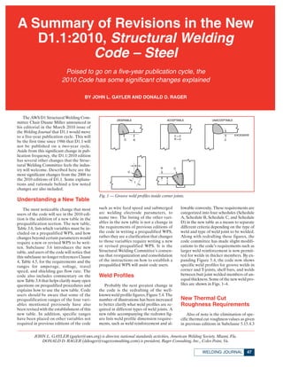
- 1. The AWS D1 Structural Welding Com- mittee Chair Duane Miller announced in his editorial in the March 2010 issue of the Welding Journal that D1.1 would move to a five-year publication cycle. This will be the first time since 1986 that D1.1 will not be published on a two-year cycle. Aside from this significant change in pub- lication frequency, the D1.1:2010 edition has several other changes that the Struc- tural Welding Committee feels the indus- try will welcome. Described here are the most significant changes from the 2008 to the 2010 editions of D1.1. Some explana- tions and rationale behind a few noted changes are also included. Understanding a New Table The most noticeable change that most users of the code will see in the 2010 edi- tion is the addition of a new table in the prequalification section. The new table, Table 3.8, lists which variables must be in- cluded on a prequalified WPS, and how changes beyond certain parameters would require a new or revised WPS to be writ- ten. Subclause 3.6 introduces the new table, and users of the code will notice that this subclause no longer references Clause 4, Table 4.5, for the requirements and the ranges for amperage, voltage, travel speed, and shielding gas flow rate. The code also includes commentary on the new Table 3.8 that helps clarify many open questions on prequalified procedures and explains how to use the new table. Code users should be aware that some of the prequalification ranges of the four vari- ables mentioned previously have also been revised with the establishment of this new table. In addition, specific ranges have been placed on other variables not required in previous editions of the code such as wire feed speed and submerged arc welding electrode parameters, to name two. The listing of the other vari- ables in the new table is not a change in the requirements of previous editions of the code in writing a prequalified WPS, rather they are a clarification that changes to those variables require writing a new or revised prequalified WPS. It is the Structural Welding Committee’s consen- sus that reorganization and consolidation of the instructions on how to establish a prequalified WPS will assist code users. Weld Profiles Probably the next greatest change in the code is the redrafting of the well- known weld profile figures, Figure 5.4. The number of illustrations has been increased to better clarify what weld profiles are re- quired in different types of weld joints. A new table accompanying the redrawn fig- ure lists weld profile dimension require- ments, such as weld reinforcement and al- lowable convexity. These requirements are categorized into four schedules (Schedule A, Schedule B, Schedule C, and Schedule D) in the new table as a means to separate different criteria depending on the type of weld and type of weld joint to be welded. Along with redrafting these figures, the code committee has made slight modifi- cations to the code’s requirements such as larger weld reinforcement is now permit- ted for welds in thicker members. By ex- panding Figure 5.4, the code now shows specific weld profiles for groove welds in corner and T-joints, shelf bars, and welds between butt joint welded members of un- equal thickness. Some of the new weld pro- files are shown in Figs. 1–4. New Thermal Cut Roughness Requirements Also of note is the elimination of spe- cific thermal cut roughness values as given in previous editions in Subclause 5.15.4.3 47WELDING JOURNAL A Summary of Revisions in the New D1.1:2010, Structural Welding Code – Steel Poised to go on a five-year publication cycle, the 2010 Code has some significant changes explained BY JOHN L. GAYLER AND DONALD D. RAGER JOHN L. GAYLER (gayler@aws.org) is director, national standards activities, American Welding Society, Miami, Fla. DONALD D. RAGER (ddrager@ragerconsulting.com) is president, Rager Consulting, Inc., Coles Point, Va. Fig. 1 — Groove weld profiles inside corner joints.
- 2. and measured to the requirements of ASME B46.1. Now, the new thermal cut roughness values are tied solely to the comparison samples found in AWS C4.1, Oxygen Cutting Surface Roughness Gauge. The requirements in previous code edi- tions have been deemed overly prescrip- tive, and the code committee thought it appropriate to change the requirements to a comparative standard. Access Holes and Beam Copes Requirements for weld access holes and beam copes are revised in this edi- tion. Weld access hole dimensions have been modified, and mandatory minimum and recommended maximum depth di- mensions of access holes have been set to prevent those that are unnecessarily deep or that are too shallow. The new code also permits a smaller radius on reentrant cor- ners in connection material and beam copes, as the 1-in. (25-mm) radius re- quirement of previous codes is not sup- ported by research and is excessive for many connection details. Beam copes in galvanized sections must now be ground to bright metal to reduce the possibility of cracking. Preheating before thermal cutting of beam copes and weld access holes in heavy shapes is now mandatory to reduce the formation of a hard surface layer and the tendency to initiate cracks. Revised Backing Requirements The code committee has revised the re- quirements for backing, found in Sub- clause 5.10, to allow for discontinuous backing in some limited statically loaded hollow structural steel (HSS) applications. There are limiting factors including diam- eter and wall thickness of the HSS shape that control when noncontinuous backing may be permitted, and there are, of course, a few code exceptions to these limitations. Prequalification and Qualification Under Subclause 3.3, the matching and undermatching table has been revised to clarify that a filler metal chosen for join- ing a combination of two different strength base materials need only match either of the two materials for the selec- tion to be considered “matching.” Like- wise, “undermatching” was clarified to mean a selection of filler metal whose strength is less than either of the base met- als being joined. The requirements of Subclause 3.7.3 have been expanded to include all weath- JULY 201048 Fig. 4 — Typical shelf bar details. Fig. 2 — Groove weld profiles in T-joints. Fig. 3 — Fillet weld profiles for outside corner joints.
- 3. ering steels, not just ASTM A 588. ASTM A 709 HPS50W has been added as a pre- qualified material in Group II of Table 3.1 and Group B of Table 3.2. ASTM A1043 Grades 36 and 50 have been added to Table 4.9. A new subclause under 3.13 (CJP Groove Weld Requirements) has been added to clarify that only steel backing is considered prequalified for nontubular welds made from one side only. The use of material other than steel for backing in a one-sided nontubular weld may be used if qualified by test in accordance with Clause 4 (Qualification). The code clarifies by revisions to 4.35.3 that if an existing qualified WPS is to be used for applications requiring impacts but CVN tests were not done during the initial qualification of that WPS then a procedure test plate needs to be per- formed but only impact tests are required to be run. The other tests associated with a WPS being qualified by test, having been completed during the original WPS Qual- ification need not be repeated. Stud Size A 3 ⁄8-in. (10-mm) stud size has been added to the code, and the tolerances on existing stud sizes have been revised to allow manufacturers to produce products that comply with both international and American standards. These tolerance changes do not adversely affect the physi- cal or mechanical properties of the studs. Commentary on ESW, EGW, and UT New commentary on electroslag and electrogas welding (ESW and EGW) has been added as assistance to users in im- plementing these welding processes. Also, commentary to alert users when applying ESW and EGW on quench and tempered steels, thermomechanical control processed steel, and precipitation hard- ened steels subjected to cyclic loading ap- plications has been added. Both potential and current users of these processes should read through the new commentary to better understand potential pitfalls and possible remedies suggested there. Additional commentary has been added to emphasize that the ultrasonic testing (UT) acceptance criteria shown in Tables 6.2 and 6.3 have been established within specific testing parameters and that using testing equipment or procedures, such as transducers of a different size or angle shown in these tables, may invali- date the results. Other Changes • The code no longer requires the Type 1 IIW UT Reference Block; any of the IIW “type” blocks may be used. • Cracks or bursts in headed studs are now covered in detail, and the maximum length of these cracks has been established. • A definition for “tubular” has been added to Annex K along with a revised definition for “pipe.” • Annex N, Form N-3 (ESW/EGW) has been completely revised. • Some guidance has been added to the introductory page of the commentary to assist users in distinguishing commen- tary on code from items supporting commentary. • The words “thorough fusion” have been changed to “complete fusion” in Table 6.1 (visual acceptance criteria) to match the terminology used in AWS A3.0, Standard Welding Terms and Definitions. Many other changes, mostly minor, have been made to this new edition of the D1.1 Code. The new foreword has a com- prehensive but succinct list of all changes. Most changes are also identified in the published code by underlined text or ver- tical lines in the margins of the page.o 49WELDING JOURNAL