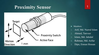
Proximity Sensor
•
41 gefällt mir•13,647 views

A proximity sensor is a sensor able to detect the presence of nearby objects without any physical contact. It detects An Object When The Object Approaches Within The Detection Range And Boundary Of The Sensor. Proximity Sensor Includes All The Sensor That Perform Non-Contact Detection In Comparison To Sensors Such As Limit Switch, That Detect The Object By Physically Contacting Them. It is a sensor able to detect the presence of nearby objects without any physical contact

Empfohlen
Weitere ähnliche Inhalte
Was ist angesagt?
Was ist angesagt? (20)
Ähnlich wie Proximity Sensor
Ähnlich wie Proximity Sensor (20)
Kürzlich hochgeladen
Kürzlich hochgeladen (20)
Proximity Sensor
- 2. Proximity sensor 2 o A proximity sensor is a sensor able to detect the presence of nearby objects without any physical contact. A proximity sensor often emits an electromagnetic field or a beam of electromagnetic radiation (infrared, for instance), and looks for changes in the field. The maximum distance that this sensor can detect is defined "nominal range". Some sensors have adjustments of the nominal range. Proximity sensors are commonly used on smartphones to detect (and skip) accidental touchscreen taps when held to the ear during a call. They are also used in machine vibration monitoring to measure the variation in distance between a shaft and its support bearing. This is common in large steam turbines, compressors, and motors that use sleeve-type bearings.
- 3. Proximity Sensors - Applications • Detects Aluminum Components • Inspects High-speed Table Movement • Detects Bottle Caps • Detects Aluminum Caps 3
- 4. • Detects the Height of Liquid in a Pipe • Detects Instruction Sheets in Paper Boxes • Provides Long-distance Detection of Aluminum • Liquid Level Control of Various Pipes and Liquid 4
- 5. Types of Proximity sensor Inductive Proximity sensor Capacitive Proximity sensor Photoelectric Proximity sensor Magnetic Proximity sensor 5
- 7. PT 7 Magnetic field o An inductive proximity sensor is an electronic proximity sensor, which detects metallic objects without touching them. The sensor consists of an induction loop. Electric current generates a magnetic field, which collapses generating a current that falls asymptotically toward zero from its initial trans when the input electricity ceases. The inductance of the loop changes according to the material inside it and since metals are much more effective inductors than other materials the presence of metal increases the current flowing through the loop. This change can be detected by sensing circuitry, which can signal to some other device whenever metal is detected.
- 9. Sensor Head 9 Consists of closed-loop op-amp configuration Has a tank circuit connected to the non-inverting input head One branch of the tank contains a capacitor and the other branch an inductor Once power applied, resonance develops in the tank and oscillators will produce a frequency(100Hz to 1MHz) Filtered rectifier which converts the AC signal into a DC voltage level Oscillator The coil of the tank inductor is wound around a ferrite core An electromagnetic field continually expands and contracts around the coil Shape of the core causes the flux lines to bundle together Unshielded sensor, which directs the flux lines to the front and side the sensor head.
- 10. 10 Evaluation Unit The function of the output is to drive a load ON or OFF. It's consists of an NPA current sinking transistor or a current sourcing device Output Stage Output of the demodulator connected to a Schmitt trigger input Produces two voltages If demodulator decreases to certain amplitude, it causes the trigger output to quickly to a low voltage level
- 11. 11 Eddy currents are electric currents induced within conductors by a changing magnetic field in the conductor These circulating eddies of current have inductance and thus induce magnetic fields. Eddy current Whenever a metal object enters this magnetic field, the moving flux lines induce small Eddy currents on the object’s surface
- 12. 12 Inductive sensors are ideal for environments in which grease or dirt builds up on the sensor or target because the magnetic field is not affected by these conditions. • Power is needed to make these currents flow, energy is drained from the oscillator circuit, causing its amplitude to decrease. • A trigger circuit inside the sensor detects the change in amplitude and causes the sensor output to switch on. • when the metal target moves out of the magnetic field, the oscillator regenerates and the sensor output switches back to its normal off state
- 13. APPLICATION 13 Application 1: Determination of position with the use of two inductive sensors. Application 2: Interrogation of a camshaft gear with inductive sensors
- 15. Capacitive Sensor: 15 Capacitive sensors can directly sense a variety of things—motion, chemical composition, electric field—and, indirectly, sense many other variables which can be converted into motion or dielectric constant, such as pressure, acceleration, fluid level, and fluid composition. They are built with conductive sensing electrodes in a dielectric, with excitation voltages on the order of five volts and detection circuits which turn a capacitance variation into a voltage, frequency, or pulse width variation. The range of application of capacitive sensors is extraordinary.
- 16. Circuit: 16 Note: For proper operation, circuit ground must be connected via a small value, high voltage-rating capacitor to one side of the mains supply socket. The "Live" side is the right one.
- 17. Capacitive proximity sensors working principle Capacitive sensors are used for non-contact detection of metallic objects & non-metallic objects(liquid, plastic, wooden materials and soon). Capacitive proximity sensors use the variation of capacitance between the sensor and the object being detected. When the object Is at a preset distance from the sensitive side of the sensor, an electronic circuit inside the sensor begins to oscillate. The rise or fall of such oscillation is identified by at threshold circuit that changes the output of the sensor. 17
- 18. Applications Capacitive touch sensors are used in many devices such as laptop track pads, digital audio players, computer displays, mobile phones, mobile devices and others. More and more design engineers are selecting capacitive sensors for the versatility, reliability and robustness and cost reduction over mechanical switches. 18
- 20. What is magnetic proximity switch: 20 Magnetic sensors are actuated by the presence of a permanent magnet. Their operating principle is based on the use of reed contacts, which consist of two low reluctance Ferro-magnetic reeds enclosed in glass bulbs containing inert gas. The reciprocal attraction of both reeds in the presence of a magnetic field, due to magnetic induction, establishes an electrical contact.
- 21. Circuit Diagram 21 When a magnet is reached in proximity of S1 it closes to give a negative trigger at pin 2 of IC1.The output of IC1 goes high. time determines by R2 and C2.This clocks the IC2 wired as a toggle flip flop. The output (pin 1 ) of IC2 goes high and the transistor. Q1 is biased to ON. The relay is activated and so do the equipment connected to the relay. The LED D1 glows when IC1 is triggered. Here is the circuit diagram of a magnetic proximity switch that finds a lot of applications in many fields. The circuit is based on a magnetic reed switch(S1) as the proximity sensor. A monostable multivibrator based on NE555 (IC1) and a toggle flip flop based on CD4013 (IC2) does the rest of the circuit.
- 22. Magnetic sensors compared to traditional mechanical switches have the following advantage: • Contacts are well protected against dust, oxidization and corrosion due to the hermetic glass bulb and inert gas; contacts are activated by means of a magnetic field rather than mechanical parts • Special surface treatment of contacts assures long contact life • Maintenance free • Easy operation • Reduced size • Reed sensors can withstand higher voltage than typical Hall devices. 22 Advantage
- 24. A photoelectric sensor, or photo eye, is a device used to detect the distance, absence, or presence of an object by using a light transmitter, often infrared , and a photoelectric receiver. They are used extensively in industrial manufacturing. • Types: There are three different functional Photoelectric Sensor 1. opposed (through beam), 2. retro-reflective 3. proximity-sensing (diffused). 24
- 25. Detection configuration and features 25 Type Detection configuration Features Model Through beam Detection occurs when the target crosses the beam between transmitter and receiver *Long-detecting distance *Stable detection *Opaque objects are detectable regardless of shape, color or material *Powerful beam LV,LX2,PZ-M,PZ2,PS,PW,PJ,PJ‐S,PQ and FS,FS2,FS-L units Retro-reflective Detection occurs when the target crosses the beam between sensor head and reflector. *Reflector allows for installation in a limited space *Simple wiring *Easily-adjustable optical axis *Opaque objects are detectable regardless of shape, color, or material PZ-M,PZ2,PW and LV,FS units Diffuse-reflective Detection occurs when the light beam is reflected by the target and received by the sensor *Space-saving *Adjustment of optical axis not required *Reflective transparent objects are detectable *Color differentiation possible PZ2,PS,PW, and FS,FS2 units Focused-beam reflective Detection occurs when the beam spot is reflected by the target and received by the sensor *Minute objects detectable *Target markings detectable LV and FS,FS2,FS-L units
- 26. Type Detection configuration Features Model Small-spot definite reflective The transmitting and receiving portions are constructed at an angle allowing detection within the limited area where the optical axes intersect *Effect of target background minimal *Low hysteresis *Slight height differences detectable PS, and FS,FS2,LV units (Internal lens units) Fixed-distance Detects the target at a specific distance according to the angle of the reflected light beam *Unaffected by highly reflective target background *Stable detection of targets of colors and materials with varying reflectance *Highly accurate detection of minute objects PZ-V,PZ-M Luster recognition When the light beam hits a target, the beam reflects differently according to the luster of the target. The sensor detects the difference in luster based on how the beam reflects (specular or diffusive) light *Detection is not affected by target color. *Transparent targets can be detected. PI-G 26
- 27. Thank You All 27