
Empfohlen
Weitere ähnliche Inhalte
Was ist angesagt?
Was ist angesagt? (20)
Ähnlich wie Compression Ii
Ähnlich wie Compression Ii (20)
Mehr von anithabalaprabhu
Mehr von anithabalaprabhu (20)
Kürzlich hochgeladen
Kürzlich hochgeladen (20)
Compression Ii
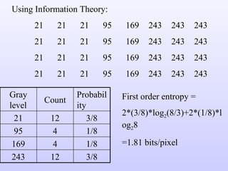
- 1. Using Information Theory: 21 21 21 95 169 243 243 243 21 21 21 95 169 243 243 243 21 21 21 95 169 243 243 243 21 21 21 95 169 243 243 243 First order entropy = 2*(3/8)*log 2 (8/3)+2*(1/8)*log 2 8 =1.81 bits/pixel Gray level Count Probability 21 12 3/8 95 4 1/8 169 4 1/8 243 12 3/8
- 2. Second-order entropy = 2*(1/4)*log 2 4+4*(1/8)*log 2 8=1+1.5=2.5 bits/pair = 1.25 bits/pixel. Gray level pair Count Probability (21,21) 8 ¼ (21,95) 4 1/8 (95,169) 4 1/8 (169,243) 4 1/8 (243,243) 8 ¼ (243,21) 4 1/8
- 3. The fact that the second order entropy (in bits/pixel) is less than the first order entropy, indicates the presence of inter-pixel redundancy. Hence variable length coding alone will not lead to the most optimum compression in this case. Consider mapping the pixels of the image to create the following representation: 21 0 0 74 74 74 0 0 21 0 0 74 74 74 0 0 21 0 0 74 74 74 0 0 21 0 0 74 74 74 0 0
- 4. Here, we construct a difference array by replicating the first column of the original image and using the arithmetic difference between adjacent columns for the remaining elements. First order entropy of this difference image = 1.41 bits/pixel Gray level or difference Count Probability 0 16 ½ 21 4 1/8 74 12 3/8
- 5. Near optimal variable length codes: Huffman codes require an enormous number of computations. For N source symbols, N-2 source reductions (sorting operations) and N-2 code assignments must be made. Sometimes we sacrifice coding efficiency for reducing the number of computations.
- 8. Truncated Huffman code: A truncated Huffman code is generated by Huffman coding only the most probable M symbols of the source, for some integer M (less than the total N symbols). A prefix code followed by a suitable fixed length is used to represent all other source symbols. In the table in the previous slide, M was arbitrarily selected as 12 and the prefix code was generated as the 13 th Huffman code word. That is a 13 th symbol whose probability is the sum of the probabilities of the symbols from 13 th to 21 st is included in the Huffman coding along with the first 12 symbols.
- 9. B-code: It is close to optimal when the source symbols probabilities obey a law of the form: P(a j ) = c j - In the B-code, each code word is made up of continuation bits, denoted C, and information bits, which are binary numbers. The only purpose of the continuation bits is to separate individual code words, so they simply toggle between 0 and 1 for each new code word. The B-code shown here is called a B 2 code, because two information bits are used per continuation bit.
- 12. Arithmetic coding: Unlike the variable-length codes described previously, arithmetic coding , generates non-block codes. In arithmetic coding, a one-to-one correspondence between source symbols and code words does not exist. Instead, an entire sequence of source symbols (or message) is assigned a single arithmetic code word. The code word itself defines an interval of real numbers between 0 and 1. As the number of symbols in the message increases, the interval used to represent it becomes smaller and the number of information units (say, bits) required to represent the interval becomes larger. Each symbol of the message reduces the size of the interval in accordance with the probability of occurrence. It is supposed to approach the limit set by entropy.
- 13. Arithmetic coding Let the message to be encoded be a 1 a 2 a 3 a 3 a 4
- 14. 0.2 0.4 0.8 0.04 0.08 0.16 0.048 0.056 0.072 0.0592 0.0624 0.0688 0.06368 0.06496
- 15. So, any number in the interval [0.06752,0.0688) , for example 0.068 can be used to represent the message. Here 3 decimal digits are used to represent the 5 symbol source message. This translates into 3/5 or 0.6 decimal digits per source symbol and compares favourably with the entropy of -(3x0.2log 10 0.2+0.4log 10 0.4) = 0.5786 digits per symbol
- 17. 1.0 0.8 0.4 0.2 0.8 0.72 0.56 0.48 0.4 0.0 0.72 0.688 0.624 0.592 0.592 0.5856 0.5728 0.5664 Therefore, the message is a 3 a 3 a 1 a 2 a 4 0.5728 0.57152 056896 0.56768 Decoding: Decode 0.572. Since 0.8>code word > 0.4, the first symbol should be a 3 . 0.56 0.56 0.5664
- 20. Example: 39 39 126 126 39 39 126 126 39 39 126 126 39 39 126 126
- 24. Recognized Encoded value pixels Dic. address Dic. entry 39 39 39 39 39 256 39-39 39 126 126 257 39-126 126 126 126 258 126-126 126 256 39-39 259 126-39 256 258 126-126 260 39-39-126 258 260 39-39-126 261 126-126-39 260 259 126-39 262 39-39-126-126 259 257 39-126 263 126-39-39 257 126 126 264 39-126-126
- 25. INTERPIXEL REDUNDANCY Variable length coding will produce identical compression ratios for the two images shown on the next slide, however we can achieve higher compression ratios by reducing interpixel redundancy. We can detect the presence of correlation between pixels (or interpixel redundancy) by computing the auto-correlation coefficients along a row of pixels
- 26. Maximum possible value of n) is 1 and this value is approached for this image, both for adjacent pixels and also for pixels which are separated by 45 pixels (or multiples of 45).
- 27. Chapter 8 Image Compression
- 31. An m-bit gray scale image can be converted into m binary images by bit-plane slicing. These individual images are then encoded using run-length coding. However, a small difference in the gray level of adjacent pixels can cause a disruption of the run of zeroes or ones. Eg: Let us say one pixel has a gray level of 127 and the next pixel has a gray level of 128. In binary: 127 = 01111111 & 128 = 10000000 Therefore a small change in gray level has decreased the run-lengths in all the bit-planes!
- 33. Let g m-1 …….g 1 g 0 represent the gray code representation of a binary number. Then: In gray code: 127 = 01000000 128 = 11000000
- 37. Decoding a gray coded image: The MSB is retained as such,i.e.,
- 40. Decompression: Most general form : Most Simple form
- 41. Example for Lossless Predictive coding
- 44. Delta modulation (DM) is a well-known form of lossy predictive coding in which the predictor and quantizer are defined as:
- 45. DELTA MODULATION
- 48. TRANSFORM CODING
- 51. Zig-zag coding is done after the quantization as shown below 4333222122200000 4.32 3.12 3.01 2.41 2.74 2.11 1.92 1.55 2.11 1.33 0.32 0.11 1.62 0.44 0.03 0.02 0 0 0 2 0 0 1 2 2 2 2 3 2 3 3 4