SlideShare ist ein Scribd-Unternehmen logo
1 von 60
Downloaden Sie, um offline zu lesen
Broadband System - D
                           Satellites are spaced every
                            2nd degrees above earth


"C" Band
Toward satellite 6.0 GHz                                 "L" Band
Toward earth 4.0 GHz                                     Toward satellite 14.0 GHz
                                                         Toward earth 12.0 GHz


                TV
            TRANSMITTER
                           Headend

                                       Cable area

                                                                                     1
                    Coaxial Cable and Fiber Optic.
Coaxial Cable.


•Coaxial cable gives the possibility of transporting electrical signal, like Television
signal and other types of signal.
•CATV, Coaxial cable frequency’s response is from; 5 to 1000 MHz.
•Coaxial cable is also capable of transporting 60 or 90 Volts AC, needed to
activate RF amplifier and other type of active equipment.
•Coaxial cable has a 75 ohms impedance +/- 2 ohms.
•VSWR (Structural Return Loss) is 37 dB and better.

•The Construction of the Coaxial cable consist of:
•An aluminium tube, sometime covered with a PVC protecting sheath.
•A centre conductor (solid cooper or cooper clad)
•The central conductor is held in place by foam.
•There are (2) Two types of coaxial cable been produced;

•P-III, an aluminium tube, squeeze around the foam and the centre conductor.
•QR, a flat aluminium plate, rounded and solder around the foam.
                                                                                   2
Coaxial Cable.


HFC System bandwidths are increasing to 750 MHz and 1 GHz. As the CATV industry moves
                                                                   the
forward, we must be continually looking out for better ways of doing things. This is the case
                                                               doing
with cable measurements as we push the frequency range up to 1 GHz. To meet these need
                                                                   GHz.
coaxial cable must meet the following;

•Insertion Loss to 1 GHz.
The insertion loss or attenuation of the cable describes how signal loses energy as it travels
                                                             signal
through the cable. The loss is usually described in terms of a power ratio in dB and it
                                                                    power
increases with the signal frequency. For coaxial cables these losses are attributed to the
                                                                 losses
conductor and the dielectric. The electrical properties of these materials are well known;
thus the insertion loss is predictable from DC to 1 GHz.

•Impedance.
The cable characteristic impedance is the ration of the voltage to current for a wave
traveling in the cable. Ideally coaxial cable impedance appears purely resistive across the
frequency band and CATV coaxial cables are designated to have 75 ohm impedance, the
standard used by CATV industry. 75 ohms is nearly the optimum impedance for the lowest
                                                                     impedance
attenuation. For higher frequencies, greater than 5 MHz, the coaxial impedance is related to
                                                                       impedance
the ration of the inner conductor dimensions and the dielectric between them. Unfortunately,
the cable impedance is not exactly 75 ohms across the frequency band and is generally
within +/- 2 ohms from 75 for trunk and feeder cable and within +/- 3 ohms for drop cable.
        +/-                                                     +/-
                                                                                           3
Coaxial Cable.


•Return Loss.
When the cable impedance is not exactly 75 ohms, there will be an impedance
mismatch and a reflection of energy if it is connected to an ideal 75 ohms signal
source. This reflection can be quantified in terms of the return loss:


                                           Z DEVICE - Z0
                  RL = 20 LOG
                                           Z DEVICE + Z0
Where Z DEVICE is the complex characteristic impedance of the device (ohms)
and Z0 is 75 ohms for CATV system.
Since the cable impedance is within a few ohms of 75, the return loss, as
opposed to the cable’s structural return loss, is very good and usually better
then 37 dB. The structural return loss, which deals with return loss at particular
frequencies, will be discussed next.


                                                                                 4
Coaxial Cable.

•Structural Return Loss.
As coaxial cable is manufactured, a number of variables can cause the impedance
to change. Recall, the cable’s impedance is a function of the cable’s physical
properties (conductor diameters, insulation’s dielectric constant) and if any of
these properties change, the impedance will change. For example, the dielectric
material is extruded over the centre conductor during manufacturing process. As
the dielectric is extruded, its diameter or dielectric constant can change and
cause the impedance to change. This impedance change is extremely small and
difficult to measure. If only one of these impedance changes occurs in the cable
or if they occur at random intervals, the return loss will be good; but due to
manufacturing processes, there may be many evenly spaced impedance changes
and return loss problem will arise. Reflection from these evenly spaced
impedance changes add together at a frequency corresponding to a half
wavelength spacing. Although, each impedance change may be very small, when
they all add together, they cause a return loss “spike”. These spikes can be
narrower than 200 KHz. The return loss from these impedance changes is called
the structural return loss because the impedance variations are due to structural
no uniformities in the cable. The challenge for measuring cable to 1 GHz is
complicated and the test equipment must have extended bandwidth (greater than
600 MHz) without sacrificing the ability to resolve and accurately measure these
sharp SRL spikes.
                                                                             5
P – III - Coaxial Cable.


             Central conductor.
                     conductor.
                                               P-III- Coaxial cable is made with the
                                                    following steps;
                                               1.   Centre conductor is spray with glue so it
                                                    will stay in position when covert with
                                                    foam.
      Central conductor and foam.
                                               2.   The centre conductor is then covert with
                                                    foam, which is then also spray with glue.
                                               3.   The foam and the centre conductor are
                                                    then installed in a aluminium tube.
                                               4.   The aluminium tube is then compressed
Coaxial Cable been press into final product.
                                    product.        three time to make the final coaxial cable.
                                               5.   When needed, the coaxial cable can be
                                                    covert with PVC jacket. This jacket will
                                                    protect the aluminium from been damaged
                                                    by the environnement.

        Final product covert with PCV.
                                  PCV.

                                                                                          6
QR - Coaxial Cable.


                      Central conductor.
                                                     QR - Coaxial cable is made with the
                 Central conductor and foam.            following steps;
                                                     1.   Centre conductor is spray with glue so it
                                                          will stay in position when covert with
                                                          foam.

         Central conductor, foam and pressed tube.   2.   The centre conductor is then covert with
                                                          foam, which is then spray with glue.
Aluminium is
                                                     3.   An aluminium Flat plate is then roll and
Solder by RF.
                                                          compressed around the foam. This
                                                          aluminium plate once wrapped around the
                                                          foam is welded together by an RF
                Final product covert with PCV.            soldering.
                                                     4.   When needed the coaxial cable can be
                                                          covert with PVC jacket, this will keep the
                                                          aluminium tube away from been damage
                                                          by the environnement.


                                                                                              7
Coaxial Cable.


In General coaxial cable has the following electrical characteristic;


•75 OHMS impedance +/- 2 ohms.
•Velocity of propagation 89% minimal.
•Capacitance of 15.2 pF/Ft. or 49.9 pFMt.
•Frequency response between 5 to 1000 MHz, depending on the type.
•DC resistance at 68 degrees F. (20 C.) in OHMS per 1000 Ft. or Mt.


                                                                      8
P – III - Coaxial Cable Dimensions.


                          P - III - 1000”
                          P - III - 875”
                          P - III - 750”
                          P - III - 625”
                          P - III - 500”
                          P - III - 412”


The center conductor
will have a different
diameter depending on
the size of the cable


                                                     9
P – III - Coaxial Cable Signal Loss.


                              Signal loss.
              5       30    50     300    550    750    870    1000    MHz

P-III-500    0.16    0.39   0.50   1.28   1.77   2.10   2.33   2.53   dB-100'
P-III-625    0.12    0.31   0.40   1.04   1.45   1.72   1.94   2.11   dB-100'
P-III-750    0.10    0.26   0.34   0.86   1.20   1.43   1.60   1.74   dB-100'
P-III-875    0.09    0.22   0.28   0.74   1.03   1.23   1.40   1.53   dB-100'
P-III-1000   0.08    0.20   0.26   0.68   0.96   1.16   1.32   1.44   dB-100'

                    DC Resistance Cooper-Clad center
P-III-500            1.70 1000'           5.58 1000mt
P-III-625            1.09   "             3.58    "
P-III-750            0.75   "             2.46    "
P-III-875            0.55   "             1.80    "
P-III-1000           0.41   "             1.35    "
                                                        Above at 68º F (20º C)
                                                                 68º (20º

                                                                                 10
QR - Coaxial Cable Dimensions.


                         QR - 1125”
                         QR - 860”
                         QR - 715”
                         QR - 540”


The center conductor
will have a different
diameter depending on
the size of the cable


                                                11
QR - Coaxial Cable Signal Loss.


                           Signal loss.
           5       30    50     300    550    750    870    1000    MHz

QR-540    0.14    0.34   0.44   1.13   1.56   1.85   2.00   2.17   dB-100'
QR-715    0.11    0.27   0.35   0.89   1.26   1.49   1.62   1.75   dB-100'
QR-860    0.09    0.23   0.30   0.76   1.06   1.24   1.33   1.44   dB-100'
QR-1125   0.07    0.17   0.22   0.50   0.84   1.01   1.11   1.20   dB-100'


                 DC Resistance Cooper-Clad center
QR-540            1.61 1000'           5.28 1000mt
QR-715            0.997  "             3.27    "
QR-860            0.724  "             2.38    "   Above at 68º F (20º C)
QR-1125           0.420  "             1.38    "


                                                                             12
Coaxial Cable Behaviour with Temperature.


The changes in temperature will affect the transmission of the electron (frequency)
inside a coaxial cable. The hotter it gets inside the cable the harder it is for the
electron to circulates, causing a higher loss in dB at all frequencies. If the inside of
the cable get cold, this will permit the electrons to circulates easier, causing less
loss.
Since the loss of all coaxial cables are giving at; 68 degrees F. or 20 degrees C.
There will be an increase or a decreased in loss specification of all coaxial cable
when the temperature changes. For every degrees F. changes at any frequency,
starting from 68.0 degrees F. there will be a loss or a gain of 0.0011% per feet. For
the Celsius temperature, there will be an add or extra loss of 0.002% per meter.
             Formula:
             Att at 68 F { 1+0.001 (t-68)}
             Att at 20 C { 1+0.002 (t-20)”
             Example: Calculate the loss at –20 F of 20 dB of cable:
             Att 20 F {1+.0011 (-20 – 68)} = 18.06 dB
                                                                                   13
Coaxial Cable Behaviour with Temperature.


Coaxial cable technical characteristics changed with temperature. The cable stay
the same length, but will act as it has lost couple of hundred feet, when the
temperature get cold and it will do the opposite during warm weather.
                                    Output previous amplifier                                                           Input next amplifier after 30 dB spacing at 870 MHz
       50   100   150   200   250    300   350   400   450   500   550   600   650   700   750   800   850             50   100   150    200   250   300    350    400    450   500   550   600   650   700   750   800   850
  49                                                                                                         49   31                                                                                                            31


  48                                                                                                         48   30                                                                                                            30

  47                                                                                                         47   29                                                                                                            29

  46                                                                                                         46   28                                                                                                            28

  45                                                                                                         45   27                                                                                                            27

  44                                                                                                         44   26                                                                                                            26

  43                                                                                                         43   25                                                                                                            25

  42                                                                                                         42   24                                                                                                            24

  41                                                                                                         41                                                   -40 o
                                                                                                                  23                                                                                                            23

  40                                                                                                         40                                                                                                                 22
                                                                                                                  22

  39                                                                                                         39
                                                                                                                                                                  60 o
                                                                                                                  21                                                                                                            21

  38                                                                                                         38
                                                                                                                  20                                                                                                            20
                                                                                                                                                                  140 o
  37                                                                                                         37
                                                                                                                  19                                                                                                            19
                                                                                                                                                            er
                                                                                                                                               cable equaliz
  36                                                                                                         36
                                                                                                                  18
                                                                                                                                  Signal after                                                                                  18


                                                                                                                  17                    Signal after cable equalizer                                                            17


                                                                                                                  16                                                                                                            16
                                                                                                                                    Signal after cable
                                                                                                                                                           equalizer            4
                                                                                                                  15                                                            9                                               15
                                                                                                                                                                                9
                                                                                                                                                                                .
                                                                                                                  14                                                                                                            14
                                                                                                                                                                                2
                                                                                                                                                                                5
                                                                                                                  13                                                                                                            13
                                                                                                                       50   100   150    200   250   300   350    400     450   500   550   600   650   700   750   800   850   14
Coaxial Cable Behaviour with Temperature.


One more problem with coaxial cable and temperature changes, is the moving of
the cable while been supported by the strand. Coaxial cable will required
expansion loops at each pole to minimized this movement, weather there is
equipment or not at each pole location.


                                  Where equipment should
                                         be placed
                                                                         15
Coaxial Cable and distance between Amplifiers.


To calculate the distance between amplifiers, you need to know the following;
•Maximum frequency of the system in MHz.
•Type of cable to be utilised, size and type.
•The loss in dB per feet of the cable at maximum frequency of the system.
•Operating gain of the amplifier, at the maximum frequency of the system.

Calculating the spacing between two (2) amplifiers;
•Frequency 870 MHz.
•Cable T-10 / 625.
•Loss of cable at 870 MHz; 1.95 dB per 100 feet or 6.4 dB per 100 meter.
•Operating gain of amplifier; 36 dB at 870 MHz.
Distance calculation;
36 / 1.95 = 18.367 X 100 feet = 1,836.73 feet between amplifier.
36 / 6.40 = 5.625 X 100 metre = 562.5 metre between amplifier.
                                                                            16
Coaxial Cable and distance between Amplifiers.


The spacing between the amplifier will depends on the maximum frequency of the
system and the distance between the amplifiers.
Let say the spacing between these two amplifiers is 1,800 feet, and we are using P-III-
625 cable.

A 450 MHz system, spacing will be : 24.30 dB spacing. (loss is 1.35 dB/100’)

A 550 MHz system, spacing will be : 27.18 dB spacing. (loss is 1.51 dB/100’)

A 750 MHz system, spacing will be : 32.22 dB spacing. (loss is 1.79 dB/100’)

A 870 MHz system, spacing will be : 34.92 dB spacing. (loss is 1.95 dB/100’)
                                                                                 17
Coaxial Cable and Equalizer Formulas.


Cable Loss Ration
The ratio of cable attenuation at two frequencies is approximately equal to the
square root of the ration of the two frequencies.
Example: What is the cable loss at 55 MHz when the loss is 20 dB at 450 MHz


           Cable Loss Ratio =                     6.99 dB


Calculate the cable loss at 55 MHz when the loss at 450 MHz when the TILT is
12 dB between 55 and 450 MHz:

                                      12
                   dB of cable                 = 18.45 dB


                                                                            18
Coaxial Cable and Equalizer Formulas.


Tilt to Cable Loss
To convert tilt (differential en signal level between end frequencies of the
cable bandpass) to cable loss at higher frequency:

                                 Tilt(dB)
                  dB of Cable=
                                        f1
                                  1-
                                        f2


Calculate the cable loss at 870 MHz when the tilt is 26 dB between 55 and
870 MHz
                                   26
                                              = 24.454 dB
               dB of Cable=
                                        55
                                  1-
                                        870

                                                                               19
Coaxial Cable and DC current.


Loop Resistance vs Temperature
Cable loop resistance is the draw in ohms of the coaxial cable. This draw is
less with bigger cable and more with smaller cable.
It is generally given at 68 degrees F. or 20 degrees C.

          Cable : 500        625       750       870      1000
          CA        1.72     1.10      0.76      0.55     0.40
          SC        1.20     0.79      0.56      0.41
         CA = Cooper Clad Aluminium Centre Conductor
          SC = Solid Copper Centre Conductor

Calculate the loop resistance at 120° F when the resistance is 3.0 ohms at
68° degrees F.
               R at 120° F. = 3 {1+.0022 (120 – 68 )} = 3.34 Ohms

                                                                          20
Coaxial Cable and DC current.


                                21
Types of Coaxial Cable.


                          22
Preparation of a Coaxial Cable Before the Installation of a
                             Connector.


The first operation, before installing a connector on coaxial cable, is to strip
the PVC of the cable, if existing.


                                                                              23
Preparation of a Coaxial Cable Before the Installation of a
                                Connector.


You then have to remove the foam between the centre conductor and the inside of
the aluminium tube. This operation will permits the introduction of the ingress
sleeve.


                                                                          24
Preparation of a Coaxial Cable Before the Installation of a
                               Connector.


You then have to remove the glue on the centre conductor, this will assure a good
connection between the jaws of the connector and the centre conductor.
The removal of the glue should be done with a plastic object not to scratch the
centre conductor.

                                                                             25
Preparation of a Coaxial Cable Before the Installation of a
                          Connector.


You then need to cut the centre conductor to the length requires
               by the connector you are using.
                                                                   26
Preparation of a Coaxial Cable Before the Installation of a
                         Connector.


Completed preparation of the end of the coaxial cable, before
             the installation of the connector.

                                                                27
Proper Installation of the Connector.


                             Sub low sleeve


Final installation of the connector equipped with sub-low sleeve.


                                                                    28
Fiber Optic.


               29
How Fiber Optic is Made.


Fiber optic comes from a Preform made of silica, and other products.
The first operation consist on building a PREFORM, that will be melted
into a solid center of 8.5 to 9.0 microns for singlemode fiber and in a
solid center of 50.0 or 62.5 microns for multimode fiber.


                                                                    30
How Fiber Optic is Made.


A PREFORM been produced


                           31
How Fiber Optic is Made.


A PREFORM nearly completed.


                              32
How Fiber Optic is Made.


PREFORM


                                     33
How Fiber Optic is Made.


                 Draw Tower


Final fiber optic before colour
    coding Is been applied
                                                  34
How Fiber Optic is Fabricated.


PREFORM been heated


                    Furnace


                   Checking the measurement ( 8 to 9 microns)


                   Adding cladding


                   Adding the coating (250 microns)


        Fiber optic been roll on a spooled.
                                                            35
How Fiber Optic is Made.


Optic PREFORM been melting into fiber optic.
                                               36
How Fiber Optic is Made.


Below is a fiber which consist of the CORE “ where light is been
propagated, CLADDING ” which keep the light inside the CORE” and
BUFFER which is colour coated and permit the identification of the fiber.


                                                                    37
How Fiber Optic is Made.


Colour been added to the fiber optic for identification.
                                                           38
Fiber Optic Frequency range .


                                39
Advantages of Fiber Optic.


• Low Optical Signal Loss - Reduces or eliminates active devices in the
  outside plant.
• High Optical Bandwidth - Large quantity of information can be rapidly
  transmitted.
• Does Not Produce, nor Is Affected by Electromagnetic Interference.
• Small and Light - Easy to install, high duct efficiency.
• Cost.


                                                                   40
Type of Communications with Fiber Optic.


Two types of technologies exits in fiber optic;

•Multimode, where many paths of light are been transmitted.
•Singlemode where only one single light path is transmitted.


•In HFC Broadband System, only Singlemode fiber optic is used.


                                                               41
Fiber Optic Cable.


            Loose tube fiber                                Ribbon fiber
Fiber optic cable comes in many flavours, most common flavours, are losses tube
fiber and ribbon fiber. These fiber cables can be armoured for duck placing or
buried installation or just plain jacketed for aerial placing.


                                 Arial Fiber Optic Cable


                               Figure 8 Fiber Optic Cable


                               Armoured Fiber Optic Cable                  42
Fiber Optic.


 The chart below shows the frequency and the signal loss of modern fiber optic.
 •1310 nm = 0.33 dB per kilometre
 •1550 nm = 0.19 dB per kilometre.

   Performance Characteristics of single mode fiber optic.
         Single-mode standard fiber optic                                        AllWave single-mode fiber optic
                Spectral Attenuation ( typical fiber ):                                 Spectral Attenuation ( AllWave fiber ):
   4.0                                                                     4.0
                                                       nm     dB/km                                                             nm     dB/km
   3.5                                                                     3.5
                                            a          850     1.81                                                  a          850        1.81
                                            b          1300    0.35                                                  b          1300       0.35
   3.0                                      c          1310    0.34        3.0                                       c          1310       0.34
                                            d          1380    0.55                                                  d          1380       0.55
   2.5                                                                     2.5

dB 2.0
                                                                      dB
                                                                           2.0

   1.5                                                                     1.5

   1.0                                                                     1.0

   0.5                                     b c         d        e          0.5

   0.0                                                                     0.0
          800          1000       1200          1400          1600                800           1000       1200          1400           1600
                                   nm                                                                       nm


                                     Moisture peak
                                                                                        Moisture peak
                                                                                          removed                                                 43
Building a Fiber Optic Link for a Broadband System.


Things to do before building a fiber optic link for a Broadband system;


•   Determine the number of customer each NODE will feed.
•   The forward operating optical frequency; 1310 or 1550 nm.
•   How many fiber optic to leave at each NODE, for future use.
•   Will the optical transmitter feed one NODE or will we use the coupler / splitter
    technology to feed many NODE.
•   The right optical input required at each NODE.
•   How many return signal from NODE will be mixed at the headend.


                                                                               44
Building a Fiber Optic Link for a Broadband System.


•Determining the number of customer the NODE will feed signal to.

Determining the number of customer per NODE is a very important function.
Deciding on the wrong number of customer per NODE could mean another
rebuilt in a near future. The number of subscribers been feed per NODE, can
be any where from 50 to 1500. The return path usually determine the number
of subscribers been feed per NODE. Cablemodem service or IP telephony
usually requires a smaller amount of subscribers per NODE.


            Node                 Amp.                     Amp.


                                                  Stanby
                                                Power Supply


                                                                 Amp.
                                                                         45
Determining the number of NODE required.


Existing CATV system, before been modernized to a HFC system.


           RF amplifier   Coaxial cable   Power Supply          46
HFC system.

         Same CATV system modernized to a HFC system.


Pocket
                                                                                               Pocket


          Optical receiver   Coaxial cable   Fiber optic cable   Bi-directional RF amplifier   47
Building a Fiber Optic Link for a Broadband System.


•The forward operating optical frequency; 1310 or 1550 nm
The maximum distance between a headend and a NODE operating at 1310 nm, is
around 35 to 40 kilometres. This distance will also depend on the bandwidth of
the system, 550, 750 or 870 MHz and the number of TV channel to be delivered.
With 1550 nm frequency and the use of EDFA (Erbium Doped Fiber Amplifier) a
link can be as much as 100 kilometres from the HEADEND.
                            35 kilometers
          Headend
                                                 60 kilometers
           Signal
                                                            50-870 MHz
                                             1310 nm.                    NODE
                                                             5-40 MHz


                                50-870 MHz
                                                        1550 nm.
                                5-40 MHz                                        NODE


                                                                                       48
Building a Fiber Optic Link for a Broadband System.


•How many fiber optic to leave at each NODE for future use.

Even if one fiber is enough to get a NODE working in both direction, two fiber
are usually required. Not knowing what the future will required, many operator
are leaving as much as 8 to 12 fiber per NODE.
Operating with one fiber per NODE, two frequencies 1310 and 1550 nm are
required. A WDM (Wave Division Multiplexing) is required at each end, to permit
both frequencies to work on the same fiber. This is sometime done, when not
enough fiber were installed at the start of a Broadband System.
             Headend
              Signal
                                                              1550 nm.


                                             50-870 MHz
                                                              WDM
                                             5-40 MHz
                                                                           NODE


                                       One Fiber                1310 nm.


                            WDM


                                                                                  49
Description of a WDM.


                        50
Building a Fiber Optic Link for a Broadband System.


  One optical transmitter can supply signal to one or many NODE. If
 one transmitter is feeding many NODE, the fiber link will require the
                   use of optical splitter or coupler.


                                50-870 MHz
               1310 nm.
                                 5-40 MHz        NODE


                                                                                NODE


                 NODE                          NODE


You need to calculate the loss of each coupler, so each NODE will receive the right input.
                                                             will

                                                                                        51
Building a Fiber Optic Link for a Broadband System.


   The loss in % and dB of the dual wave (1310 - 1550 nm)
                of optical splitter & coupler.
 50 / 50 %        3.6 / 3.6 dB
 55 / 45 %        3.2 / 4.1 dB
 60 / 40 %        2.7 / 4.7 dB
 65 / 35 %        2.3 / 5.3 dB
 70 / 30 %        2.2 / 5.7 dB
 75 / 25 %        1.8 / 6.8 dB
 80 / 20 %        1.3 / 7.8 dB
 85 / 15 %        1.0 / 9.2 dB
 90 / 10 %        0.8 / 11.2 dB
 95 / 5 %         0.5 / 14.4 dB


In most cases, you will need to add the fusion splices to these loss.
                                                                    52
Building a Fiber Optic Link for a Broadband System.
              Using 1 transmitter for 3 optical NODE using optical couplers.


                      Forward signal input @ 1310 nm at Optical NODE.
                                            Optical                   Optical
      0.4    dB loss / km @ 1310 nm
                                            Coupler                   Coupler

                            8.0       km              7.3    km                 9.0    km
      13.0                                    1.4                      2.5                      -0.6
                            3.2   dB loss    10.0     2.9   dB loss    5.6      3.6   dB loss   dBm
                                             -0.2                      -0.1
                                             dBm                       dBm


                    Return signal input @ 1310 nm from Optical NODES.

      -9.7                                                                                      0.0


      -6.1                                                             0.0


      -3.2                                    0.0


Notice here, that I am using 0.4 dB loss / km at 1310 nm, when the actual loss is 0.33 dB / km.
                                                                  the
 By using this as the actual loss, I do not have to calculate the extra loss for connectors and
                               fusion splicing in the optical link.                          53
Building a Fiber Optic Link for a Broadband System.


•The right optical power input required at each NODE.
 In a modern system each NODE require an input of : –1.0 to +2.0 dBm. We
 should always try to hit the receiver at 0.0 dBm. With this level and modern DFB
                                                             level
 (Distributed Feed Back) laser, the NODE,s technical specification should be:
                                                      specification
 C/N: 52.00 dB for 77 channels in CW mode.
      52.00
 CTB: -65.00 dB for 77 channels in CW mode.
 CSO: -63.00 dB for 77 channels in CW mode.

Reducing the number of carried channels from 77 to 40, will increase the Carrier to
                                                               increase
Noise specification by 3.0 dB, but will not better the CTB and CSO specification.
                                                               CSO
Every dB away from 0.0 dBm input, will increase or decrease the C/N by one dB.
Then a –1.0 dBm input will give 52.00 dB C/N and a +2.0 dBm will give a 55.00 dB
C/N.
We should never hit a NODE with more than +2.0 dBm input. Optical input signal
                                                                      input
above +2.0 dBm will either shorten the receiving photo diode’s life or will get the
                                                               life
NODE to go into distortion.

                                                                                    54
Building a Fiber Optic Link for a Broadband System.


The right number of return signal from NODE;

Ideally every NODE should have it own return sent directly to the CMTS.
Because of cost and to-day need, the industry is now presently mixing four
(4) return signal from NODE per combining network.


                                          From NODE - 1
                                          From NODE - 2
                                          From NODE - 3
                                          From NODE - 4


                                                                        55
Building a Fiber Optic Link for a Broadband System.


                                       Broadband Combining Network

                                                      Forward RF                     Return RF
                                                       Combiner                      Combiner
                                                     Rear of unit                    Rear of unit
                                                 Common   1   2     3   4        Common   1   2   3   4


                                                                                                                                                         Sweep Rx


                                                                                                                                           NODE
                                                                                                                                                  5-42
                                                                                                                                                  MHz


                                                                                                           Fiber optic Return 5 - 40 MHz
                                                                                                           Fiber optic Forward 50 - 870 MHz MHz


   Monitoring System
                                                                                                          Optical Equipment
    Coaxial Cable Return 5 - 40 MHz
    Coaxial Cable Forward 50 - 870 MHz MHz


                                                                                                                         Return Alignment and
                                                                                                                        Ingress Control System

                                  Cablemodem
Headend Equipment                 IP-Telephone


                                                                  50-52 / 73.5
                                                                     MHz

  Forward Tx Sweep

  50-1000 MHz                         Sweep Rx

                                                                                                                                                                    56
Fiber Optic Cable.


     We will comes back to the
technology fiber optic later on, in the
              seminar.


                                          57
TEST!


        58
•Name two types of signal a coaxial cable can carry?
_____________________________________________________________
•What is the impedance of coaxial cable used in a HFC system?
_____________________________________________________________
•Name the two types of coaxial cable used for a HFC system in North America?
______________________________________________________________
•What is the maximum and minimum temperature coaxial cable are spec at?
______________________________________________________________
•What type of AC wave comes out of a power supply used in a HFC system?
_______________________________________________________________
•Name two types of passives equipment used in a HFC system?
________________________________________________________________
•How many types of multitap can we used in a HFC system?
_________________________________________________________________
                                                                               59
60

Weitere ähnliche Inhalte

Was ist angesagt?

Backhaul Ppt
Backhaul PptBackhaul Ppt
Backhaul Pptwillyaoll
 
A very quick introduction to HFC, DOCSIS 3.0 and 3.1
A very quick introduction to HFC, DOCSIS 3.0 and 3.1A very quick introduction to HFC, DOCSIS 3.0 and 3.1
A very quick introduction to HFC, DOCSIS 3.0 and 3.1Erik Vloothuis
 
Red telefónica de conmutación pública pstn
Red telefónica de conmutación pública pstnRed telefónica de conmutación pública pstn
Red telefónica de conmutación pública pstnChristopher Rodriguez
 
Training document e ran2.2_lte tdd system multiple antenna techniques(mimo an...
Training document e ran2.2_lte tdd system multiple antenna techniques(mimo an...Training document e ran2.2_lte tdd system multiple antenna techniques(mimo an...
Training document e ran2.2_lte tdd system multiple antenna techniques(mimo an...ProcExpl
 
Television por cable
Television por cableTelevision por cable
Television por cablehamilton2014
 
Probabilidad de error de símbolo m pam modificado
Probabilidad de error de símbolo m pam modificadoProbabilidad de error de símbolo m pam modificado
Probabilidad de error de símbolo m pam modificadoPato Villacis
 
LTE Physical layer aspects
LTE Physical layer aspectsLTE Physical layer aspects
LTE Physical layer aspectsBP Tiwari
 
Gprs (General Packet Radio Service)
Gprs (General Packet Radio Service)Gprs (General Packet Radio Service)
Gprs (General Packet Radio Service)Proyecto Bonnzai
 
Meios de fibra ótica
Meios de fibra óticaMeios de fibra ótica
Meios de fibra óticaH P
 
Práctica nº 12 amplificadores de f.i., detector de video y c.a.g. -
Práctica nº 12   amplificadores de f.i., detector de video y c.a.g. -Práctica nº 12   amplificadores de f.i., detector de video y c.a.g. -
Práctica nº 12 amplificadores de f.i., detector de video y c.a.g. -Jodanica83
 
Seminar report on Millimeter Wave mobile communications for 5g cellular
Seminar report on Millimeter Wave mobile communications for 5g cellularSeminar report on Millimeter Wave mobile communications for 5g cellular
Seminar report on Millimeter Wave mobile communications for 5g cellularraghubraghu
 
Manual de treinamento Proeletronic
Manual de treinamento  ProeletronicManual de treinamento  Proeletronic
Manual de treinamento ProeletronicRenato Monteiro
 

Was ist angesagt? (20)

Backhaul Ppt
Backhaul PptBackhaul Ppt
Backhaul Ppt
 
A very quick introduction to HFC, DOCSIS 3.0 and 3.1
A very quick introduction to HFC, DOCSIS 3.0 and 3.1A very quick introduction to HFC, DOCSIS 3.0 and 3.1
A very quick introduction to HFC, DOCSIS 3.0 and 3.1
 
Redes NGN
Redes NGNRedes NGN
Redes NGN
 
Red telefónica de conmutación pública pstn
Red telefónica de conmutación pública pstnRed telefónica de conmutación pública pstn
Red telefónica de conmutación pública pstn
 
Training document e ran2.2_lte tdd system multiple antenna techniques(mimo an...
Training document e ran2.2_lte tdd system multiple antenna techniques(mimo an...Training document e ran2.2_lte tdd system multiple antenna techniques(mimo an...
Training document e ran2.2_lte tdd system multiple antenna techniques(mimo an...
 
Television por cable
Television por cableTelevision por cable
Television por cable
 
Probabilidad de error de símbolo m pam modificado
Probabilidad de error de símbolo m pam modificadoProbabilidad de error de símbolo m pam modificado
Probabilidad de error de símbolo m pam modificado
 
Comunicaciones analogicas
Comunicaciones analogicasComunicaciones analogicas
Comunicaciones analogicas
 
LTE Physical layer aspects
LTE Physical layer aspectsLTE Physical layer aspects
LTE Physical layer aspects
 
Radioenlaces
RadioenlacesRadioenlaces
Radioenlaces
 
SPEECH CODING
SPEECH CODINGSPEECH CODING
SPEECH CODING
 
Gprs architecture
Gprs architectureGprs architecture
Gprs architecture
 
Gprs (General Packet Radio Service)
Gprs (General Packet Radio Service)Gprs (General Packet Radio Service)
Gprs (General Packet Radio Service)
 
Meios de fibra ótica
Meios de fibra óticaMeios de fibra ótica
Meios de fibra ótica
 
Práctica nº 12 amplificadores de f.i., detector de video y c.a.g. -
Práctica nº 12   amplificadores de f.i., detector de video y c.a.g. -Práctica nº 12   amplificadores de f.i., detector de video y c.a.g. -
Práctica nº 12 amplificadores de f.i., detector de video y c.a.g. -
 
Seminar report on Millimeter Wave mobile communications for 5g cellular
Seminar report on Millimeter Wave mobile communications for 5g cellularSeminar report on Millimeter Wave mobile communications for 5g cellular
Seminar report on Millimeter Wave mobile communications for 5g cellular
 
Manual de treinamento Proeletronic
Manual de treinamento  ProeletronicManual de treinamento  Proeletronic
Manual de treinamento Proeletronic
 
Spread spectrum modulation
Spread spectrum modulationSpread spectrum modulation
Spread spectrum modulation
 
Conmutacion y transmision digital
Conmutacion y transmision digitalConmutacion y transmision digital
Conmutacion y transmision digital
 
Lte training session_1
Lte training session_1Lte training session_1
Lte training session_1
 

Andere mochten auch

Andere mochten auch (20)

Broadband Access Over HFC Networks
Broadband Access Over HFC NetworksBroadband Access Over HFC Networks
Broadband Access Over HFC Networks
 
Hfc
HfcHfc
Hfc
 
Hfc network 2
Hfc network 2Hfc network 2
Hfc network 2
 
Hfc a catv-101
Hfc a catv-101Hfc a catv-101
Hfc a catv-101
 
Redes Hibridas De Fibra óPtica Y Cable Coaxial
Redes Hibridas De Fibra óPtica Y Cable CoaxialRedes Hibridas De Fibra óPtica Y Cable Coaxial
Redes Hibridas De Fibra óPtica Y Cable Coaxial
 
And ... A Single Solution
And ... A Single SolutionAnd ... A Single Solution
And ... A Single Solution
 
HFC Architecture In The Making
HFC Architecture In The MakingHFC Architecture In The Making
HFC Architecture In The Making
 
Tutorial transmission line details
Tutorial transmission line detailsTutorial transmission line details
Tutorial transmission line details
 
Network fundamental
Network fundamentalNetwork fundamental
Network fundamental
 
Curso Basico Catv capitulo 2
Curso Basico Catv capitulo 2Curso Basico Catv capitulo 2
Curso Basico Catv capitulo 2
 
Csc339 – lecture 2 network fundamental
Csc339 – lecture 2 network fundamentalCsc339 – lecture 2 network fundamental
Csc339 – lecture 2 network fundamental
 
Curso Basico CATV Capitulo 01
Curso Basico CATV Capitulo 01Curso Basico CATV Capitulo 01
Curso Basico CATV Capitulo 01
 
2013 A miniature fiber optic blood pressure sensor and its application in in-...
2013 A miniature fiber optic blood pressure sensor and its application in in-...2013 A miniature fiber optic blood pressure sensor and its application in in-...
2013 A miniature fiber optic blood pressure sensor and its application in in-...
 
Fog 2
Fog 2Fog 2
Fog 2
 
optical_fiber_sensor_system
optical_fiber_sensor_systemoptical_fiber_sensor_system
optical_fiber_sensor_system
 
FOG 2
FOG 2FOG 2
FOG 2
 
01. network topologies & cable
01. network topologies & cable01. network topologies & cable
01. network topologies & cable
 
Fiber Optic Gyroscope 1
Fiber Optic Gyroscope 1Fiber Optic Gyroscope 1
Fiber Optic Gyroscope 1
 
The Sagnac Effect
The Sagnac EffectThe Sagnac Effect
The Sagnac Effect
 
Mesuring ph with FOS (Fibre Optic Sensors)
Mesuring ph with FOS (Fibre Optic Sensors)Mesuring ph with FOS (Fibre Optic Sensors)
Mesuring ph with FOS (Fibre Optic Sensors)
 

Ähnlich wie Hfc d coaxial fiber optic

Coaxial Cable
Coaxial CableCoaxial Cable
Coaxial CableMissAnam
 
Coaxial cable research report by alina baber
Coaxial cable research report by alina baberCoaxial cable research report by alina baber
Coaxial cable research report by alina baberAlina Baber
 
Best fit topology - LO1 part II
Best fit topology - LO1 part IIBest fit topology - LO1 part II
Best fit topology - LO1 part IIAbenezer Abiti
 
Coaxial cable installation
Coaxial cable installationCoaxial cable installation
Coaxial cable installationVinod Jadhav
 
UNDERSTANDING FIBER OPTIC PRINCIPLES PP
UNDERSTANDING FIBER OPTIC PRINCIPLES PPUNDERSTANDING FIBER OPTIC PRINCIPLES PP
UNDERSTANDING FIBER OPTIC PRINCIPLES PPAjiboye Zaccheous
 
Coaxial cable by alina baber
Coaxial cable by alina baberCoaxial cable by alina baber
Coaxial cable by alina baberAlina Baber
 
Communication - Line Communication Class 12 Part-6
Communication - Line Communication Class 12 Part-6Communication - Line Communication Class 12 Part-6
Communication - Line Communication Class 12 Part-6Self-employed
 
6_line_communication.ppt
6_line_communication.ppt6_line_communication.ppt
6_line_communication.pptAKCreation22
 
Capacitance and Cable Testing
Capacitance and Cable TestingCapacitance and Cable Testing
Capacitance and Cable TestingHussein Kassem
 
Coaxial cable Kurdish Seminar By Teacher Azad Jabre
Coaxial cable Kurdish Seminar By Teacher Azad JabreCoaxial cable Kurdish Seminar By Teacher Azad Jabre
Coaxial cable Kurdish Seminar By Teacher Azad JabreAzad Mzuri
 
Basics Of Electrical Wires & Cables - Residential & Commercial Projects
Basics Of  Electrical  Wires & Cables  - Residential & Commercial Projects Basics Of  Electrical  Wires & Cables  - Residential & Commercial Projects
Basics Of Electrical Wires & Cables - Residential & Commercial Projects SSudhaVelan
 
Coaxial cable and its types
Coaxial cable and its typesCoaxial cable and its types
Coaxial cable and its typesAdeel Khurram
 
Presentation on cables
Presentation on cablesPresentation on cables
Presentation on cablesFaizanAli244
 

Ähnlich wie Hfc d coaxial fiber optic (20)

Coaxial Cable
Coaxial CableCoaxial Cable
Coaxial Cable
 
COAXIAL CABLES
COAXIAL CABLESCOAXIAL CABLES
COAXIAL CABLES
 
Cable
CableCable
Cable
 
Coaxial cable research report by alina baber
Coaxial cable research report by alina baberCoaxial cable research report by alina baber
Coaxial cable research report by alina baber
 
Best fit topology - LO1 part II
Best fit topology - LO1 part IIBest fit topology - LO1 part II
Best fit topology - LO1 part II
 
Coaxial cable installation
Coaxial cable installationCoaxial cable installation
Coaxial cable installation
 
UNDERSTANDING FIBER OPTIC PRINCIPLES PP
UNDERSTANDING FIBER OPTIC PRINCIPLES PPUNDERSTANDING FIBER OPTIC PRINCIPLES PP
UNDERSTANDING FIBER OPTIC PRINCIPLES PP
 
Coaxial cable by alina baber
Coaxial cable by alina baberCoaxial cable by alina baber
Coaxial cable by alina baber
 
Communication - Line Communication Class 12 Part-6
Communication - Line Communication Class 12 Part-6Communication - Line Communication Class 12 Part-6
Communication - Line Communication Class 12 Part-6
 
6_line_communication.ppt
6_line_communication.ppt6_line_communication.ppt
6_line_communication.ppt
 
Capacitance and Cable Testing
Capacitance and Cable TestingCapacitance and Cable Testing
Capacitance and Cable Testing
 
Coaxial cable Kurdish Seminar By Teacher Azad Jabre
Coaxial cable Kurdish Seminar By Teacher Azad JabreCoaxial cable Kurdish Seminar By Teacher Azad Jabre
Coaxial cable Kurdish Seminar By Teacher Azad Jabre
 
Basics Of Electrical Wires & Cables - Residential & Commercial Projects
Basics Of  Electrical  Wires & Cables  - Residential & Commercial Projects Basics Of  Electrical  Wires & Cables  - Residential & Commercial Projects
Basics Of Electrical Wires & Cables - Residential & Commercial Projects
 
Underground cables
Underground cablesUnderground cables
Underground cables
 
Sheath bonding method for underground cables
Sheath bonding method for underground cablesSheath bonding method for underground cables
Sheath bonding method for underground cables
 
Coaxial cables
Coaxial cablesCoaxial cables
Coaxial cables
 
Coaxial cable and its types
Coaxial cable and its typesCoaxial cable and its types
Coaxial cable and its types
 
coax_construction
coax_constructioncoax_construction
coax_construction
 
Telecom Cables
Telecom CablesTelecom Cables
Telecom Cables
 
Presentation on cables
Presentation on cablesPresentation on cables
Presentation on cables
 

Mehr von jose angel guzman lozano (15)

Cabecera
CabeceraCabecera
Cabecera
 
Capacitacion+Atenuador++Mezclador
Capacitacion+Atenuador++MezcladorCapacitacion+Atenuador++Mezclador
Capacitacion+Atenuador++Mezclador
 
Hfc o cli seminar
Hfc o cli seminarHfc o cli seminar
Hfc o cli seminar
 
Hfc n test equip for hfc
Hfc n test equip for hfcHfc n test equip for hfc
Hfc n test equip for hfc
 
Hfc m home installation
Hfc m home installationHfc m home installation
Hfc m home installation
 
Hfc l alignment and system maintenance
Hfc l alignment and system maintenanceHfc l alignment and system maintenance
Hfc l alignment and system maintenance
 
Hfc k understanding bi-direction
Hfc k understanding bi-directionHfc k understanding bi-direction
Hfc k understanding bi-direction
 
Hfc j system distortion calculation
Hfc j system distortion calculationHfc j system distortion calculation
Hfc j system distortion calculation
 
Hfc i fiber management
Hfc i fiber managementHfc i fiber management
Hfc i fiber management
 
Hfc h fiber optic testing
Hfc h fiber optic testingHfc h fiber optic testing
Hfc h fiber optic testing
 
Hfc f outside plan
Hfc f outside planHfc f outside plan
Hfc f outside plan
 
Hfc e passive equip
Hfc e passive equipHfc e passive equip
Hfc e passive equip
 
Hfc c he example of hfc
Hfc c he example of hfcHfc c he example of hfc
Hfc c he example of hfc
 
Hfc b headend of hfc
Hfc b headend of hfcHfc b headend of hfc
Hfc b headend of hfc
 
Hfc q- more on docsis
Hfc q- more on docsisHfc q- more on docsis
Hfc q- more on docsis
 

Kürzlich hochgeladen

Artificial intelligence in cctv survelliance.pptx
Artificial intelligence in cctv survelliance.pptxArtificial intelligence in cctv survelliance.pptx
Artificial intelligence in cctv survelliance.pptxhariprasad279825
 
Anypoint Exchange: It’s Not Just a Repo!
Anypoint Exchange: It’s Not Just a Repo!Anypoint Exchange: It’s Not Just a Repo!
Anypoint Exchange: It’s Not Just a Repo!Manik S Magar
 
Transcript: New from BookNet Canada for 2024: BNC CataList - Tech Forum 2024
Transcript: New from BookNet Canada for 2024: BNC CataList - Tech Forum 2024Transcript: New from BookNet Canada for 2024: BNC CataList - Tech Forum 2024
Transcript: New from BookNet Canada for 2024: BNC CataList - Tech Forum 2024BookNet Canada
 
Advanced Test Driven-Development @ php[tek] 2024
Advanced Test Driven-Development @ php[tek] 2024Advanced Test Driven-Development @ php[tek] 2024
Advanced Test Driven-Development @ php[tek] 2024Scott Keck-Warren
 
SAP Build Work Zone - Overview L2-L3.pptx
SAP Build Work Zone - Overview L2-L3.pptxSAP Build Work Zone - Overview L2-L3.pptx
SAP Build Work Zone - Overview L2-L3.pptxNavinnSomaal
 
Leverage Zilliz Serverless - Up to 50X Saving for Your Vector Storage Cost
Leverage Zilliz Serverless - Up to 50X Saving for Your Vector Storage CostLeverage Zilliz Serverless - Up to 50X Saving for Your Vector Storage Cost
Leverage Zilliz Serverless - Up to 50X Saving for Your Vector Storage CostZilliz
 
Gen AI in Business - Global Trends Report 2024.pdf
Gen AI in Business - Global Trends Report 2024.pdfGen AI in Business - Global Trends Report 2024.pdf
Gen AI in Business - Global Trends Report 2024.pdfAddepto
 
Human Factors of XR: Using Human Factors to Design XR Systems
Human Factors of XR: Using Human Factors to Design XR SystemsHuman Factors of XR: Using Human Factors to Design XR Systems
Human Factors of XR: Using Human Factors to Design XR SystemsMark Billinghurst
 
TeamStation AI System Report LATAM IT Salaries 2024
TeamStation AI System Report LATAM IT Salaries 2024TeamStation AI System Report LATAM IT Salaries 2024
TeamStation AI System Report LATAM IT Salaries 2024Lonnie McRorey
 
Developer Data Modeling Mistakes: From Postgres to NoSQL
Developer Data Modeling Mistakes: From Postgres to NoSQLDeveloper Data Modeling Mistakes: From Postgres to NoSQL
Developer Data Modeling Mistakes: From Postgres to NoSQLScyllaDB
 
How AI, OpenAI, and ChatGPT impact business and software.
How AI, OpenAI, and ChatGPT impact business and software.How AI, OpenAI, and ChatGPT impact business and software.
How AI, OpenAI, and ChatGPT impact business and software.Curtis Poe
 
SIP trunking in Janus @ Kamailio World 2024
SIP trunking in Janus @ Kamailio World 2024SIP trunking in Janus @ Kamailio World 2024
SIP trunking in Janus @ Kamailio World 2024Lorenzo Miniero
 
Designing IA for AI - Information Architecture Conference 2024
Designing IA for AI - Information Architecture Conference 2024Designing IA for AI - Information Architecture Conference 2024
Designing IA for AI - Information Architecture Conference 2024Enterprise Knowledge
 
From Family Reminiscence to Scholarly Archive .
From Family Reminiscence to Scholarly Archive .From Family Reminiscence to Scholarly Archive .
From Family Reminiscence to Scholarly Archive .Alan Dix
 
H2O.ai CEO/Founder: Sri Ambati Keynote at Wells Fargo Day
H2O.ai CEO/Founder: Sri Ambati Keynote at Wells Fargo DayH2O.ai CEO/Founder: Sri Ambati Keynote at Wells Fargo Day
H2O.ai CEO/Founder: Sri Ambati Keynote at Wells Fargo DaySri Ambati
 
CloudStudio User manual (basic edition):
CloudStudio User manual (basic edition):CloudStudio User manual (basic edition):
CloudStudio User manual (basic edition):comworks
 
Search Engine Optimization SEO PDF for 2024.pdf
Search Engine Optimization SEO PDF for 2024.pdfSearch Engine Optimization SEO PDF for 2024.pdf
Search Engine Optimization SEO PDF for 2024.pdfRankYa
 
DevEX - reference for building teams, processes, and platforms
DevEX - reference for building teams, processes, and platformsDevEX - reference for building teams, processes, and platforms
DevEX - reference for building teams, processes, and platformsSergiu Bodiu
 

Kürzlich hochgeladen (20)

Artificial intelligence in cctv survelliance.pptx
Artificial intelligence in cctv survelliance.pptxArtificial intelligence in cctv survelliance.pptx
Artificial intelligence in cctv survelliance.pptx
 
Anypoint Exchange: It’s Not Just a Repo!
Anypoint Exchange: It’s Not Just a Repo!Anypoint Exchange: It’s Not Just a Repo!
Anypoint Exchange: It’s Not Just a Repo!
 
E-Vehicle_Hacking_by_Parul Sharma_null_owasp.pptx
E-Vehicle_Hacking_by_Parul Sharma_null_owasp.pptxE-Vehicle_Hacking_by_Parul Sharma_null_owasp.pptx
E-Vehicle_Hacking_by_Parul Sharma_null_owasp.pptx
 
Transcript: New from BookNet Canada for 2024: BNC CataList - Tech Forum 2024
Transcript: New from BookNet Canada for 2024: BNC CataList - Tech Forum 2024Transcript: New from BookNet Canada for 2024: BNC CataList - Tech Forum 2024
Transcript: New from BookNet Canada for 2024: BNC CataList - Tech Forum 2024
 
Advanced Test Driven-Development @ php[tek] 2024
Advanced Test Driven-Development @ php[tek] 2024Advanced Test Driven-Development @ php[tek] 2024
Advanced Test Driven-Development @ php[tek] 2024
 
DMCC Future of Trade Web3 - Special Edition
DMCC Future of Trade Web3 - Special EditionDMCC Future of Trade Web3 - Special Edition
DMCC Future of Trade Web3 - Special Edition
 
SAP Build Work Zone - Overview L2-L3.pptx
SAP Build Work Zone - Overview L2-L3.pptxSAP Build Work Zone - Overview L2-L3.pptx
SAP Build Work Zone - Overview L2-L3.pptx
 
Leverage Zilliz Serverless - Up to 50X Saving for Your Vector Storage Cost
Leverage Zilliz Serverless - Up to 50X Saving for Your Vector Storage CostLeverage Zilliz Serverless - Up to 50X Saving for Your Vector Storage Cost
Leverage Zilliz Serverless - Up to 50X Saving for Your Vector Storage Cost
 
Gen AI in Business - Global Trends Report 2024.pdf
Gen AI in Business - Global Trends Report 2024.pdfGen AI in Business - Global Trends Report 2024.pdf
Gen AI in Business - Global Trends Report 2024.pdf
 
Human Factors of XR: Using Human Factors to Design XR Systems
Human Factors of XR: Using Human Factors to Design XR SystemsHuman Factors of XR: Using Human Factors to Design XR Systems
Human Factors of XR: Using Human Factors to Design XR Systems
 
TeamStation AI System Report LATAM IT Salaries 2024
TeamStation AI System Report LATAM IT Salaries 2024TeamStation AI System Report LATAM IT Salaries 2024
TeamStation AI System Report LATAM IT Salaries 2024
 
Developer Data Modeling Mistakes: From Postgres to NoSQL
Developer Data Modeling Mistakes: From Postgres to NoSQLDeveloper Data Modeling Mistakes: From Postgres to NoSQL
Developer Data Modeling Mistakes: From Postgres to NoSQL
 
How AI, OpenAI, and ChatGPT impact business and software.
How AI, OpenAI, and ChatGPT impact business and software.How AI, OpenAI, and ChatGPT impact business and software.
How AI, OpenAI, and ChatGPT impact business and software.
 
SIP trunking in Janus @ Kamailio World 2024
SIP trunking in Janus @ Kamailio World 2024SIP trunking in Janus @ Kamailio World 2024
SIP trunking in Janus @ Kamailio World 2024
 
Designing IA for AI - Information Architecture Conference 2024
Designing IA for AI - Information Architecture Conference 2024Designing IA for AI - Information Architecture Conference 2024
Designing IA for AI - Information Architecture Conference 2024
 
From Family Reminiscence to Scholarly Archive .
From Family Reminiscence to Scholarly Archive .From Family Reminiscence to Scholarly Archive .
From Family Reminiscence to Scholarly Archive .
 
H2O.ai CEO/Founder: Sri Ambati Keynote at Wells Fargo Day
H2O.ai CEO/Founder: Sri Ambati Keynote at Wells Fargo DayH2O.ai CEO/Founder: Sri Ambati Keynote at Wells Fargo Day
H2O.ai CEO/Founder: Sri Ambati Keynote at Wells Fargo Day
 
CloudStudio User manual (basic edition):
CloudStudio User manual (basic edition):CloudStudio User manual (basic edition):
CloudStudio User manual (basic edition):
 
Search Engine Optimization SEO PDF for 2024.pdf
Search Engine Optimization SEO PDF for 2024.pdfSearch Engine Optimization SEO PDF for 2024.pdf
Search Engine Optimization SEO PDF for 2024.pdf
 
DevEX - reference for building teams, processes, and platforms
DevEX - reference for building teams, processes, and platformsDevEX - reference for building teams, processes, and platforms
DevEX - reference for building teams, processes, and platforms
 

Hfc d coaxial fiber optic

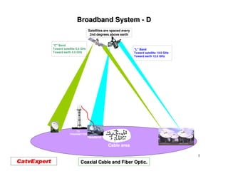
  • 1. Broadband System - D Satellites are spaced every 2nd degrees above earth "C" Band Toward satellite 6.0 GHz "L" Band Toward earth 4.0 GHz Toward satellite 14.0 GHz Toward earth 12.0 GHz TV TRANSMITTER Headend Cable area 1 Coaxial Cable and Fiber Optic.
  • 2. Coaxial Cable. •Coaxial cable gives the possibility of transporting electrical signal, like Television signal and other types of signal. •CATV, Coaxial cable frequency’s response is from; 5 to 1000 MHz. •Coaxial cable is also capable of transporting 60 or 90 Volts AC, needed to activate RF amplifier and other type of active equipment. •Coaxial cable has a 75 ohms impedance +/- 2 ohms. •VSWR (Structural Return Loss) is 37 dB and better. •The Construction of the Coaxial cable consist of: •An aluminium tube, sometime covered with a PVC protecting sheath. •A centre conductor (solid cooper or cooper clad) •The central conductor is held in place by foam. •There are (2) Two types of coaxial cable been produced; •P-III, an aluminium tube, squeeze around the foam and the centre conductor. •QR, a flat aluminium plate, rounded and solder around the foam. 2
  • 3. Coaxial Cable. HFC System bandwidths are increasing to 750 MHz and 1 GHz. As the CATV industry moves the forward, we must be continually looking out for better ways of doing things. This is the case doing with cable measurements as we push the frequency range up to 1 GHz. To meet these need GHz. coaxial cable must meet the following; •Insertion Loss to 1 GHz. The insertion loss or attenuation of the cable describes how signal loses energy as it travels signal through the cable. The loss is usually described in terms of a power ratio in dB and it power increases with the signal frequency. For coaxial cables these losses are attributed to the losses conductor and the dielectric. The electrical properties of these materials are well known; thus the insertion loss is predictable from DC to 1 GHz. •Impedance. The cable characteristic impedance is the ration of the voltage to current for a wave traveling in the cable. Ideally coaxial cable impedance appears purely resistive across the frequency band and CATV coaxial cables are designated to have 75 ohm impedance, the standard used by CATV industry. 75 ohms is nearly the optimum impedance for the lowest impedance attenuation. For higher frequencies, greater than 5 MHz, the coaxial impedance is related to impedance the ration of the inner conductor dimensions and the dielectric between them. Unfortunately, the cable impedance is not exactly 75 ohms across the frequency band and is generally within +/- 2 ohms from 75 for trunk and feeder cable and within +/- 3 ohms for drop cable. +/- +/- 3
  • 4. Coaxial Cable. •Return Loss. When the cable impedance is not exactly 75 ohms, there will be an impedance mismatch and a reflection of energy if it is connected to an ideal 75 ohms signal source. This reflection can be quantified in terms of the return loss: Z DEVICE - Z0 RL = 20 LOG Z DEVICE + Z0 Where Z DEVICE is the complex characteristic impedance of the device (ohms) and Z0 is 75 ohms for CATV system. Since the cable impedance is within a few ohms of 75, the return loss, as opposed to the cable’s structural return loss, is very good and usually better then 37 dB. The structural return loss, which deals with return loss at particular frequencies, will be discussed next. 4
  • 5. Coaxial Cable. •Structural Return Loss. As coaxial cable is manufactured, a number of variables can cause the impedance to change. Recall, the cable’s impedance is a function of the cable’s physical properties (conductor diameters, insulation’s dielectric constant) and if any of these properties change, the impedance will change. For example, the dielectric material is extruded over the centre conductor during manufacturing process. As the dielectric is extruded, its diameter or dielectric constant can change and cause the impedance to change. This impedance change is extremely small and difficult to measure. If only one of these impedance changes occurs in the cable or if they occur at random intervals, the return loss will be good; but due to manufacturing processes, there may be many evenly spaced impedance changes and return loss problem will arise. Reflection from these evenly spaced impedance changes add together at a frequency corresponding to a half wavelength spacing. Although, each impedance change may be very small, when they all add together, they cause a return loss “spike”. These spikes can be narrower than 200 KHz. The return loss from these impedance changes is called the structural return loss because the impedance variations are due to structural no uniformities in the cable. The challenge for measuring cable to 1 GHz is complicated and the test equipment must have extended bandwidth (greater than 600 MHz) without sacrificing the ability to resolve and accurately measure these sharp SRL spikes. 5
  • 6. P – III - Coaxial Cable. Central conductor. conductor. P-III- Coaxial cable is made with the following steps; 1. Centre conductor is spray with glue so it will stay in position when covert with foam. Central conductor and foam. 2. The centre conductor is then covert with foam, which is then also spray with glue. 3. The foam and the centre conductor are then installed in a aluminium tube. 4. The aluminium tube is then compressed Coaxial Cable been press into final product. product. three time to make the final coaxial cable. 5. When needed, the coaxial cable can be covert with PVC jacket. This jacket will protect the aluminium from been damaged by the environnement. Final product covert with PCV. PCV. 6
  • 7. QR - Coaxial Cable. Central conductor. QR - Coaxial cable is made with the Central conductor and foam. following steps; 1. Centre conductor is spray with glue so it will stay in position when covert with foam. Central conductor, foam and pressed tube. 2. The centre conductor is then covert with foam, which is then spray with glue. Aluminium is 3. An aluminium Flat plate is then roll and Solder by RF. compressed around the foam. This aluminium plate once wrapped around the foam is welded together by an RF Final product covert with PCV. soldering. 4. When needed the coaxial cable can be covert with PVC jacket, this will keep the aluminium tube away from been damage by the environnement. 7
  • 8. Coaxial Cable. In General coaxial cable has the following electrical characteristic; •75 OHMS impedance +/- 2 ohms. •Velocity of propagation 89% minimal. •Capacitance of 15.2 pF/Ft. or 49.9 pFMt. •Frequency response between 5 to 1000 MHz, depending on the type. •DC resistance at 68 degrees F. (20 C.) in OHMS per 1000 Ft. or Mt. 8
  • 9. P – III - Coaxial Cable Dimensions. P - III - 1000” P - III - 875” P - III - 750” P - III - 625” P - III - 500” P - III - 412” The center conductor will have a different diameter depending on the size of the cable 9
  • 10. P – III - Coaxial Cable Signal Loss. Signal loss. 5 30 50 300 550 750 870 1000 MHz P-III-500 0.16 0.39 0.50 1.28 1.77 2.10 2.33 2.53 dB-100' P-III-625 0.12 0.31 0.40 1.04 1.45 1.72 1.94 2.11 dB-100' P-III-750 0.10 0.26 0.34 0.86 1.20 1.43 1.60 1.74 dB-100' P-III-875 0.09 0.22 0.28 0.74 1.03 1.23 1.40 1.53 dB-100' P-III-1000 0.08 0.20 0.26 0.68 0.96 1.16 1.32 1.44 dB-100' DC Resistance Cooper-Clad center P-III-500 1.70 1000' 5.58 1000mt P-III-625 1.09 " 3.58 " P-III-750 0.75 " 2.46 " P-III-875 0.55 " 1.80 " P-III-1000 0.41 " 1.35 " Above at 68º F (20º C) 68º (20º 10
  • 11. QR - Coaxial Cable Dimensions. QR - 1125” QR - 860” QR - 715” QR - 540” The center conductor will have a different diameter depending on the size of the cable 11
  • 12. QR - Coaxial Cable Signal Loss. Signal loss. 5 30 50 300 550 750 870 1000 MHz QR-540 0.14 0.34 0.44 1.13 1.56 1.85 2.00 2.17 dB-100' QR-715 0.11 0.27 0.35 0.89 1.26 1.49 1.62 1.75 dB-100' QR-860 0.09 0.23 0.30 0.76 1.06 1.24 1.33 1.44 dB-100' QR-1125 0.07 0.17 0.22 0.50 0.84 1.01 1.11 1.20 dB-100' DC Resistance Cooper-Clad center QR-540 1.61 1000' 5.28 1000mt QR-715 0.997 " 3.27 " QR-860 0.724 " 2.38 " Above at 68º F (20º C) QR-1125 0.420 " 1.38 " 12
  • 13. Coaxial Cable Behaviour with Temperature. The changes in temperature will affect the transmission of the electron (frequency) inside a coaxial cable. The hotter it gets inside the cable the harder it is for the electron to circulates, causing a higher loss in dB at all frequencies. If the inside of the cable get cold, this will permit the electrons to circulates easier, causing less loss. Since the loss of all coaxial cables are giving at; 68 degrees F. or 20 degrees C. There will be an increase or a decreased in loss specification of all coaxial cable when the temperature changes. For every degrees F. changes at any frequency, starting from 68.0 degrees F. there will be a loss or a gain of 0.0011% per feet. For the Celsius temperature, there will be an add or extra loss of 0.002% per meter. Formula: Att at 68 F { 1+0.001 (t-68)} Att at 20 C { 1+0.002 (t-20)” Example: Calculate the loss at –20 F of 20 dB of cable: Att 20 F {1+.0011 (-20 – 68)} = 18.06 dB 13
  • 14. Coaxial Cable Behaviour with Temperature. Coaxial cable technical characteristics changed with temperature. The cable stay the same length, but will act as it has lost couple of hundred feet, when the temperature get cold and it will do the opposite during warm weather. Output previous amplifier Input next amplifier after 30 dB spacing at 870 MHz 50 100 150 200 250 300 350 400 450 500 550 600 650 700 750 800 850 50 100 150 200 250 300 350 400 450 500 550 600 650 700 750 800 850 49 49 31 31 48 48 30 30 47 47 29 29 46 46 28 28 45 45 27 27 44 44 26 26 43 43 25 25 42 42 24 24 41 41 -40 o 23 23 40 40 22 22 39 39 60 o 21 21 38 38 20 20 140 o 37 37 19 19 er cable equaliz 36 36 18 Signal after 18 17 Signal after cable equalizer 17 16 16 Signal after cable equalizer 4 15 9 15 9 . 14 14 2 5 13 13 50 100 150 200 250 300 350 400 450 500 550 600 650 700 750 800 850 14
  • 15. Coaxial Cable Behaviour with Temperature. One more problem with coaxial cable and temperature changes, is the moving of the cable while been supported by the strand. Coaxial cable will required expansion loops at each pole to minimized this movement, weather there is equipment or not at each pole location. Where equipment should be placed 15
  • 16. Coaxial Cable and distance between Amplifiers. To calculate the distance between amplifiers, you need to know the following; •Maximum frequency of the system in MHz. •Type of cable to be utilised, size and type. •The loss in dB per feet of the cable at maximum frequency of the system. •Operating gain of the amplifier, at the maximum frequency of the system. Calculating the spacing between two (2) amplifiers; •Frequency 870 MHz. •Cable T-10 / 625. •Loss of cable at 870 MHz; 1.95 dB per 100 feet or 6.4 dB per 100 meter. •Operating gain of amplifier; 36 dB at 870 MHz. Distance calculation; 36 / 1.95 = 18.367 X 100 feet = 1,836.73 feet between amplifier. 36 / 6.40 = 5.625 X 100 metre = 562.5 metre between amplifier. 16
  • 17. Coaxial Cable and distance between Amplifiers. The spacing between the amplifier will depends on the maximum frequency of the system and the distance between the amplifiers. Let say the spacing between these two amplifiers is 1,800 feet, and we are using P-III- 625 cable. A 450 MHz system, spacing will be : 24.30 dB spacing. (loss is 1.35 dB/100’) A 550 MHz system, spacing will be : 27.18 dB spacing. (loss is 1.51 dB/100’) A 750 MHz system, spacing will be : 32.22 dB spacing. (loss is 1.79 dB/100’) A 870 MHz system, spacing will be : 34.92 dB spacing. (loss is 1.95 dB/100’) 17
  • 18. Coaxial Cable and Equalizer Formulas. Cable Loss Ration The ratio of cable attenuation at two frequencies is approximately equal to the square root of the ration of the two frequencies. Example: What is the cable loss at 55 MHz when the loss is 20 dB at 450 MHz Cable Loss Ratio = 6.99 dB Calculate the cable loss at 55 MHz when the loss at 450 MHz when the TILT is 12 dB between 55 and 450 MHz: 12 dB of cable = 18.45 dB 18
  • 19. Coaxial Cable and Equalizer Formulas. Tilt to Cable Loss To convert tilt (differential en signal level between end frequencies of the cable bandpass) to cable loss at higher frequency: Tilt(dB) dB of Cable= f1 1- f2 Calculate the cable loss at 870 MHz when the tilt is 26 dB between 55 and 870 MHz 26 = 24.454 dB dB of Cable= 55 1- 870 19
  • 20. Coaxial Cable and DC current. Loop Resistance vs Temperature Cable loop resistance is the draw in ohms of the coaxial cable. This draw is less with bigger cable and more with smaller cable. It is generally given at 68 degrees F. or 20 degrees C. Cable : 500 625 750 870 1000 CA 1.72 1.10 0.76 0.55 0.40 SC 1.20 0.79 0.56 0.41 CA = Cooper Clad Aluminium Centre Conductor SC = Solid Copper Centre Conductor Calculate the loop resistance at 120° F when the resistance is 3.0 ohms at 68° degrees F. R at 120° F. = 3 {1+.0022 (120 – 68 )} = 3.34 Ohms 20
  • 21. Coaxial Cable and DC current. 21
  • 22. Types of Coaxial Cable. 22
  • 23. Preparation of a Coaxial Cable Before the Installation of a Connector. The first operation, before installing a connector on coaxial cable, is to strip the PVC of the cable, if existing. 23
  • 24. Preparation of a Coaxial Cable Before the Installation of a Connector. You then have to remove the foam between the centre conductor and the inside of the aluminium tube. This operation will permits the introduction of the ingress sleeve. 24
  • 25. Preparation of a Coaxial Cable Before the Installation of a Connector. You then have to remove the glue on the centre conductor, this will assure a good connection between the jaws of the connector and the centre conductor. The removal of the glue should be done with a plastic object not to scratch the centre conductor. 25
  • 26. Preparation of a Coaxial Cable Before the Installation of a Connector. You then need to cut the centre conductor to the length requires by the connector you are using. 26
  • 27. Preparation of a Coaxial Cable Before the Installation of a Connector. Completed preparation of the end of the coaxial cable, before the installation of the connector. 27
  • 28. Proper Installation of the Connector. Sub low sleeve Final installation of the connector equipped with sub-low sleeve. 28
  • 30. How Fiber Optic is Made. Fiber optic comes from a Preform made of silica, and other products. The first operation consist on building a PREFORM, that will be melted into a solid center of 8.5 to 9.0 microns for singlemode fiber and in a solid center of 50.0 or 62.5 microns for multimode fiber. 30
  • 31. How Fiber Optic is Made. A PREFORM been produced 31
  • 32. How Fiber Optic is Made. A PREFORM nearly completed. 32
  • 33. How Fiber Optic is Made. PREFORM 33
  • 34. How Fiber Optic is Made. Draw Tower Final fiber optic before colour coding Is been applied 34
  • 35. How Fiber Optic is Fabricated. PREFORM been heated Furnace Checking the measurement ( 8 to 9 microns) Adding cladding Adding the coating (250 microns) Fiber optic been roll on a spooled. 35
  • 36. How Fiber Optic is Made. Optic PREFORM been melting into fiber optic. 36
  • 37. How Fiber Optic is Made. Below is a fiber which consist of the CORE “ where light is been propagated, CLADDING ” which keep the light inside the CORE” and BUFFER which is colour coated and permit the identification of the fiber. 37
  • 38. How Fiber Optic is Made. Colour been added to the fiber optic for identification. 38
  • 39. Fiber Optic Frequency range . 39
  • 40. Advantages of Fiber Optic. • Low Optical Signal Loss - Reduces or eliminates active devices in the outside plant. • High Optical Bandwidth - Large quantity of information can be rapidly transmitted. • Does Not Produce, nor Is Affected by Electromagnetic Interference. • Small and Light - Easy to install, high duct efficiency. • Cost. 40
  • 41. Type of Communications with Fiber Optic. Two types of technologies exits in fiber optic; •Multimode, where many paths of light are been transmitted. •Singlemode where only one single light path is transmitted. •In HFC Broadband System, only Singlemode fiber optic is used. 41
  • 42. Fiber Optic Cable. Loose tube fiber Ribbon fiber Fiber optic cable comes in many flavours, most common flavours, are losses tube fiber and ribbon fiber. These fiber cables can be armoured for duck placing or buried installation or just plain jacketed for aerial placing. Arial Fiber Optic Cable Figure 8 Fiber Optic Cable Armoured Fiber Optic Cable 42
  • 43. Fiber Optic. The chart below shows the frequency and the signal loss of modern fiber optic. •1310 nm = 0.33 dB per kilometre •1550 nm = 0.19 dB per kilometre. Performance Characteristics of single mode fiber optic. Single-mode standard fiber optic AllWave single-mode fiber optic Spectral Attenuation ( typical fiber ): Spectral Attenuation ( AllWave fiber ): 4.0 4.0 nm dB/km nm dB/km 3.5 3.5 a 850 1.81 a 850 1.81 b 1300 0.35 b 1300 0.35 3.0 c 1310 0.34 3.0 c 1310 0.34 d 1380 0.55 d 1380 0.55 2.5 2.5 dB 2.0 dB 2.0 1.5 1.5 1.0 1.0 0.5 b c d e 0.5 0.0 0.0 800 1000 1200 1400 1600 800 1000 1200 1400 1600 nm nm Moisture peak Moisture peak removed 43
  • 44. Building a Fiber Optic Link for a Broadband System. Things to do before building a fiber optic link for a Broadband system; • Determine the number of customer each NODE will feed. • The forward operating optical frequency; 1310 or 1550 nm. • How many fiber optic to leave at each NODE, for future use. • Will the optical transmitter feed one NODE or will we use the coupler / splitter technology to feed many NODE. • The right optical input required at each NODE. • How many return signal from NODE will be mixed at the headend. 44
  • 45. Building a Fiber Optic Link for a Broadband System. •Determining the number of customer the NODE will feed signal to. Determining the number of customer per NODE is a very important function. Deciding on the wrong number of customer per NODE could mean another rebuilt in a near future. The number of subscribers been feed per NODE, can be any where from 50 to 1500. The return path usually determine the number of subscribers been feed per NODE. Cablemodem service or IP telephony usually requires a smaller amount of subscribers per NODE. Node Amp. Amp. Stanby Power Supply Amp. 45
  • 46. Determining the number of NODE required. Existing CATV system, before been modernized to a HFC system. RF amplifier Coaxial cable Power Supply 46
  • 47. HFC system. Same CATV system modernized to a HFC system. Pocket Pocket Optical receiver Coaxial cable Fiber optic cable Bi-directional RF amplifier 47
  • 48. Building a Fiber Optic Link for a Broadband System. •The forward operating optical frequency; 1310 or 1550 nm The maximum distance between a headend and a NODE operating at 1310 nm, is around 35 to 40 kilometres. This distance will also depend on the bandwidth of the system, 550, 750 or 870 MHz and the number of TV channel to be delivered. With 1550 nm frequency and the use of EDFA (Erbium Doped Fiber Amplifier) a link can be as much as 100 kilometres from the HEADEND. 35 kilometers Headend 60 kilometers Signal 50-870 MHz 1310 nm. NODE 5-40 MHz 50-870 MHz 1550 nm. 5-40 MHz NODE 48
  • 49. Building a Fiber Optic Link for a Broadband System. •How many fiber optic to leave at each NODE for future use. Even if one fiber is enough to get a NODE working in both direction, two fiber are usually required. Not knowing what the future will required, many operator are leaving as much as 8 to 12 fiber per NODE. Operating with one fiber per NODE, two frequencies 1310 and 1550 nm are required. A WDM (Wave Division Multiplexing) is required at each end, to permit both frequencies to work on the same fiber. This is sometime done, when not enough fiber were installed at the start of a Broadband System. Headend Signal 1550 nm. 50-870 MHz WDM 5-40 MHz NODE One Fiber 1310 nm. WDM 49
  • 50. Description of a WDM. 50
  • 51. Building a Fiber Optic Link for a Broadband System. One optical transmitter can supply signal to one or many NODE. If one transmitter is feeding many NODE, the fiber link will require the use of optical splitter or coupler. 50-870 MHz 1310 nm. 5-40 MHz NODE NODE NODE NODE You need to calculate the loss of each coupler, so each NODE will receive the right input. will 51
  • 52. Building a Fiber Optic Link for a Broadband System. The loss in % and dB of the dual wave (1310 - 1550 nm) of optical splitter & coupler. 50 / 50 % 3.6 / 3.6 dB 55 / 45 % 3.2 / 4.1 dB 60 / 40 % 2.7 / 4.7 dB 65 / 35 % 2.3 / 5.3 dB 70 / 30 % 2.2 / 5.7 dB 75 / 25 % 1.8 / 6.8 dB 80 / 20 % 1.3 / 7.8 dB 85 / 15 % 1.0 / 9.2 dB 90 / 10 % 0.8 / 11.2 dB 95 / 5 % 0.5 / 14.4 dB In most cases, you will need to add the fusion splices to these loss. 52
  • 53. Building a Fiber Optic Link for a Broadband System. Using 1 transmitter for 3 optical NODE using optical couplers. Forward signal input @ 1310 nm at Optical NODE. Optical Optical 0.4 dB loss / km @ 1310 nm Coupler Coupler 8.0 km 7.3 km 9.0 km 13.0 1.4 2.5 -0.6 3.2 dB loss 10.0 2.9 dB loss 5.6 3.6 dB loss dBm -0.2 -0.1 dBm dBm Return signal input @ 1310 nm from Optical NODES. -9.7 0.0 -6.1 0.0 -3.2 0.0 Notice here, that I am using 0.4 dB loss / km at 1310 nm, when the actual loss is 0.33 dB / km. the By using this as the actual loss, I do not have to calculate the extra loss for connectors and fusion splicing in the optical link. 53
  • 54. Building a Fiber Optic Link for a Broadband System. •The right optical power input required at each NODE. In a modern system each NODE require an input of : –1.0 to +2.0 dBm. We should always try to hit the receiver at 0.0 dBm. With this level and modern DFB level (Distributed Feed Back) laser, the NODE,s technical specification should be: specification C/N: 52.00 dB for 77 channels in CW mode. 52.00 CTB: -65.00 dB for 77 channels in CW mode. CSO: -63.00 dB for 77 channels in CW mode. Reducing the number of carried channels from 77 to 40, will increase the Carrier to increase Noise specification by 3.0 dB, but will not better the CTB and CSO specification. CSO Every dB away from 0.0 dBm input, will increase or decrease the C/N by one dB. Then a –1.0 dBm input will give 52.00 dB C/N and a +2.0 dBm will give a 55.00 dB C/N. We should never hit a NODE with more than +2.0 dBm input. Optical input signal input above +2.0 dBm will either shorten the receiving photo diode’s life or will get the life NODE to go into distortion. 54
  • 55. Building a Fiber Optic Link for a Broadband System. The right number of return signal from NODE; Ideally every NODE should have it own return sent directly to the CMTS. Because of cost and to-day need, the industry is now presently mixing four (4) return signal from NODE per combining network. From NODE - 1 From NODE - 2 From NODE - 3 From NODE - 4 55
  • 56. Building a Fiber Optic Link for a Broadband System. Broadband Combining Network Forward RF Return RF Combiner Combiner Rear of unit Rear of unit Common 1 2 3 4 Common 1 2 3 4 Sweep Rx NODE 5-42 MHz Fiber optic Return 5 - 40 MHz Fiber optic Forward 50 - 870 MHz MHz Monitoring System Optical Equipment Coaxial Cable Return 5 - 40 MHz Coaxial Cable Forward 50 - 870 MHz MHz Return Alignment and Ingress Control System Cablemodem Headend Equipment IP-Telephone 50-52 / 73.5 MHz Forward Tx Sweep 50-1000 MHz Sweep Rx 56
  • 57. Fiber Optic Cable. We will comes back to the technology fiber optic later on, in the seminar. 57
  • 58. TEST! 58
  • 59. •Name two types of signal a coaxial cable can carry? _____________________________________________________________ •What is the impedance of coaxial cable used in a HFC system? _____________________________________________________________ •Name the two types of coaxial cable used for a HFC system in North America? ______________________________________________________________ •What is the maximum and minimum temperature coaxial cable are spec at? ______________________________________________________________ •What type of AC wave comes out of a power supply used in a HFC system? _______________________________________________________________ •Name two types of passives equipment used in a HFC system? ________________________________________________________________ •How many types of multitap can we used in a HFC system? _________________________________________________________________ 59
  • 60. 60