
Empfohlen

Empfohlen
Weitere ähnliche Inhalte
Was ist angesagt?
Was ist angesagt? (19)
Andere mochten auch
Andere mochten auch (20)
Ähnlich wie Barrier mtl5544 a i b
Ähnlich wie Barrier mtl5544 a i b (20)
Kürzlich hochgeladen
Kürzlich hochgeladen (20)
Barrier mtl5544 a i b
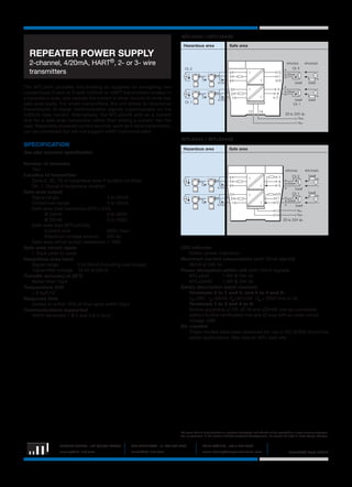
- 1. MTL4544/S – MTL5544/S REPEATER POWER SUPPLY 2-channel, 4/20mA, HART®, 2- or 3- wire transmitters The MTLx544 provides fully-floating dc supplies for energising two conventional 2-wire or 3-wire 4/20mA or HART transmitters located in a hazardous area, and repeats the current in other circuits to drive two safe-area loads. For smart transmitters, the unit allows bi-directional transmission of digital communication signals superimposed on the 4/20mA loop current. Alternatively, the MTLx544S acts as a current sink for a safe-area connection rather than driving a current into the load. Separately powered current sources, such as 4-wire transmitters, can be connected but will not support HART communication. MTL4544 / MTL4544S Hazardous area Safe area MTL4544 Ch 2 + 6 5 – 4 I I 4/20mA +3 2 – 1 I I 4/20mA Ch 1 + 13 12 4/20mA 11 – 10 9 8 7 14 MTL4544S Ch 2 + Load – Load + – 4/20mA – Load Ch 1 Load + 20 to 35V dc Vs+ Vs– MTL5544 / MTL5544S SPECIFICATION Hazardous area See also common specification Number of channels Two Location of transmitter Zone 0, IIC, T4–6 hazardous area if suitably certified Div. 1, Group A hazardous location Safe-area output Signal range: 4 to 20mA Under/over-range: 0 to 24mA Safe-area load resistance (MTLx 544) @ 24mA: 0 to 360Ω @ 20mA: 0 to 450Ω Safe-area load (MTLx544S) Current sink: 600Ω max. Maximum voltage source: 24V dc Safe-area circuit output resistance: > 1MΩ Safe-area circuit ripple < 50µA peak-to-peak Hazardous-area input Signal range: 0 to 24mA (including over-range) Transmitter voltage: 16.5V at 20mA Transfer accuracy at 20°C Better than 15µA Temperature drift < 0.8µA/°C Response time Settles to within 10% of final value within 50µs Communications supported HART (terminals 1 & 2 and 4 & 5 only) Safe area MTL5544 6 + 5 – 4 I I 4/20mA 3 + 2 – 1 I 4/20mA I 7 8 9 10 11 12 13 14 – Ch 2 MTL5544S Load 4/20mA + – Load Ch 1 4/20mA + Load + – Load + – Vs– Vs+ 20 to 35V dc LED indicator Green: power indication Maximum current consumption (with 20mA signals) 96mA at 24V dc Power dissipation within unit (with 20mA signals) MTLx544 1.4W @ 24V dc MTLx544S 1.9W @ 24V dc Safety description (each channel) Terminals 2 to 1 and 3, and 5 to 4 and 6: Uo =28V Io =93mA Po =651mW Um = 253V rms or dc Terminals 1 to 3 and 4 to 6: Simple apparatus ≤1.5V, ≤0.1A and ≤25mW; can be connected without further certification into any IS loop with an open-circuit voltage <28V SIL capable These models have been assessed for use in IEC 61508 functional safety applications. See data on MTL web site. The given data is only intended as a product description and should not be regarded as a legal warranty of properties or guarantee. In the interest of further technical developments, we reserve the right to make design changes. EUROPE (EMEA): +44 (0)1582 723633 THE AMERICAS: +1 800 835 7075 ASIA-PACIFIC: +65 6 645 9888 enquiry@mtl-inst.com csinfo@mtl-inst.com sales.mtlsing@cooperindustries.com EPSx544/S Rev3 150312