SlideShare ist ein Scribd-Unternehmen logo
1 von 31
VHDL Key Idea
  A key idea in VHDL is to define the interface of a
  hardware module while hiding its internal details.
      A VHDL entity is simply a declaration of a module’s inputs
      and outputs, i.e., its external interface signals or ports.
      A VHDL architecture is a detailed description of the
      module’s internal structure or behavior.

                   entity
interface                                             interface
                            architecture


                                                              1
VHDL Interface - Ports
   You can think of the entity as a “wrapper” for the
   architecture
       hiding the details of what’s inside
       providing “ports” to other modules

                    entity
              .
              .                              .
                                             .
input port    .              architecture    .   output port


                                                         2
VHDL Conceptual Model
VHDL actually allows you
                              entity
to define multiple
architectures for a single         architecture 1
entity
it also provides a
configuration management           architecture 2
facility that allows you to
specify which architecture
to use during a particular             configuration
synthesis run
                                                       3
VHDL Program File
In the text file of a VHDL        mydesign.vhd
program:
  the entity, architecture, and         entity
  configuration declarations
  are all separated
                                     architecture
  not nested as the previous
  diagram may have implied
We will use white space to           configuration
set them apart
                                                     4
VHDL Program File
In large projects
  the entities and architectures are sometimes
  defined in separate files, which the compiler
  matches according to their declared names
VHDL ignores spaces and line breaks
Comments begin with two hyphens (--) and
end at the end of a line
VHDL defines many special character
strings, called reserved words or keywords
                                                  5
VHDL reserved words or keywords
 Some reserved words or keywords
   entity, port, is, in, out, end,
   architecture, begin, when, else,
   not, etc.


                                      6
Elements of VHDL
 Syntax (the rules)
 Five design units (or elements)
 Identifiers (naming constraints)
 Data objects (what you name)
 Data types (enumerated, integer, arrays, etc.)
 Examples


                                                  7
VHDL Provides Five Design Units
 Entity Declaration
    Specifies the NAME and lists the interface PORTS
                                                          Our initial
 Architecture Body                                        examples will
    Models the actual circuit “guts” within an entity     focus on the
 Configuration Declaration                                first three
   Identifies which arch. should be used with an entity   design units.
   Specifies location of components used within arch.
 Package Declaration – like a header file in C
 Package Body – like an implementation file in C
    Packages are libraries containing type definitions, overloaded
    operators, components, functions, and procedures. They have a
    “declarative” section and a BODY section. Elements of a Package
    can be used by many entities in a design, or many designs.

                                                                      8
VHDL Identifiers (Names)
 Basic identifier
    starts with a letter
    made up of letters, numbers, and underscore “_” character
    cannot end with an underscore
    an underscore cannot follow an underscore
    case-insensitive: MY_Signal_Name = my_signal_name

 Extended Identifier                not recommended
    any text within 2 backslashes
    e.g., 2FOR$ -23signal etc.
    case is significant: COUNT not equal to count, and
    FRAMUS not equal to basic identifier FRAMUS
    Not often used – not necessarily supported in synthesis !!

                                                                 9
VHDL Identifiers (Names)
 Identifiers in the example
   half_adder, A, B, BIT, SUM and
   CARRY
   BIT is a built-in identifier for a predefined
   type; and not considered as a reserved word
   because it can be redefined


                                                   10
Four Classes of Data Objects
 Constant
    Holds a single value of a given type – cannot change.
 Variable
    Holds a single value of a given type.
    New value of same type can be “assigned” – (instantly)
 Signal                     analogous to a “wire”
    Holds a LIST of values of a given type.
    Present value + a set of possible future values
    New values can be assigned at some future time – not now!
    Signals have ATTRIBUTES: [signal’attribute]
 File
    Contains a sequence of values of one or more types.
    Usually read or written to using procedures
    For simulation – not synthesis

                                                                11
Data Types
 Scalar Types
   Enumerated : a list of values
   Integer
   Floating Point
   Physical : with units, for physical quantities
 Composite Types
   Array (all of same type)
   Record (can be different types)
 Access Type
 File Type

                                                    12
Entity Declaration
 Specifies the name of the entity
 Lists the set of interface PORTS
 PORTS are SIGNALS that enter or leave the entity
 This is the “black box,” or block diagram view


   A                                          SUM
                   Half-Adder
   B                                        CARRY


                                                    13
Syntax of a VHDL entity declaration
entity entity-name is
  port( signal-names : mode signal-type;
        signal-names : mode signal-type;
        …
        signal-names : mode signal-type);
end entity-name;

entity-name A user selected identifier
signal-names A comma separated list of 1 or more user selected
             identifiers
mode         One of the four reserved words
signal-type  A built in or user defined signal type

                                                             14
Entity Declaration
       entity half_adder is
         port( A, B : in BIT; SUM, CARRY : out BIT);
       end half_adder;

                   MODE
  White space is ignored

       entity half_adder is port(
NAME     A, B :    in    BIT;     TYPE
         SUM :     out   BIT;
                                             end of port statement
         CARRY :   out   BIT );
       end entity half_adder;
                                            no “;” after last signal


                           optional words, but recommended        15
VHDL Signal Modes
 in – means input-ONLY, you cannot use a mode in
 signal on the LEFT side of an equation (that is, you can’t
 assign a new value to inputs)
 out – means output-ONLY, you cannot use a mode out
 signal on the RIGHT side of an equation (that is, you
 can’t “use” the outputs)
 inout – means bi-directional, like a three-state bus, for
 example. This mode is typically used for three-state
 input/output pins on PLDs
 buffer – means the signal is an output of the entity, and
 its value can also be read inside the entity’s architecture

                                                               16
Entity Declaration
    entity half_adder is
      port( A, B : in BIT; SUM, CARRY : out std_logic);
    end half_adder;

Using IEEE 1164 standard signals and data types:

    entity half_adder is port(
      A, B :    in    std_logic;            TYPE
      SUM :     out   std_logic;
      CARRY :   out   std_logic );
    end entity half_adder;


                                                    17
Example: LogicFcn
                  ports


     A
     B
     C                                   Y


         entity           architecture
                                             18
Entity Declaration for LogicFcn
 library IEEE;
 use IEEE.std_logic_1164.all;
  entity LogicFcn is
   port (
                        A
   A: in std_logic;     B         Y
   B: in std_logic;     C

   C: in std_logic;
   Y: out std_logic
   );
 end entity LogicFcn;
                                      19
Architecture definition
An entity’s ports and their modes and types are all that is
seen by other modules that use it
The entity’s internal operation is specified in it’s
architecture definition whose general syntax is
as shown next
The entity-name in this definition must be the same as
the one given previously in the entity declaration
The architecture-name is a user selected identifier,
usually related to the entity-name; it can be the same
as the entity name if desired

                                                     20
Architecture definition
An architecture’s external interface signals (ports) are
inherited from the port-declaration part of its
corresponding entity declaration
An architecture may include signals and other declarations
that are local to that architecture
Declaration common to multiple entities can be made in a
separate “package” used by all entities
Declarations can appear in any order


                                                     21
Syntax:VHDL architecture
  architecture arch-name of entity-name is
   type declarations
   signal declarations        named wires
   constant declarations
   function definitions
   procedure definitions             later
   component declarations
  begin
   concurrent-statements
  end arch-name;
                                             22
Signal declaration
It gives the same information about a signal as in a port
declaration, except that no mode is specified:
signal signal-names : signal-type;
Zero or more signals can be defined within an architecture,
and they roughly correspond to named wires in a logic
diagram
They can be read or written within the architecture
definition and, like other local objects, can be referenced
only within the encompassing architecture definition


                                                     23
Variable declaration
  VHDL variables are similar to signals, except that they
  usually don’t have physical significance in a circuit
  Variables are used in VHDL functions, procedures and
  processes
  Within these program elements, the syntax of a variable
  declaration is just like that of a signal declaration, except
  that the variable keyword is used
variable variable-names : variable-type;


                                                           24
Types and Constants
All signals, variables and constants in aVHDL program
must have an associated “type”
The type specifies the set of range of values that the object
can take on, and there is also typically a set of operators
(such as add, AND, and so on ) associated with a given
type
VHDL has just a few predefined types
bit, character, severity_level,
bit_vector, integer, string, boolean,
real, time

                                                        25
Types and Constants
The only ones we’ll see here are integer, character,
and boolean
The built-in types bit and bit_vector may seem to
be essential in digital design, but the “user-
defined” types std_logic and std_logic_vector are
more useful (IEEE 1164 std)


                                               26
Type integers
 All implementations support 32-bit integers,
 with a range of values from –(231 – 1) to
 +(231 – 1)
 Integer data types with a smaller range can be
 defined to save hardware (no sense forcing a
 32-bit counter when you need a 4-bit counter)
 Examples of legal integers
   56349       6E2 0         98_71_28
   (Underscores can be thrown in anywhere, and
   don’t change the value of the number.)
                                                 27
Integer Operators
VHDL provides the following predefined basic
integer operators:
           Keyword      Definition
           +            addition
           -            subtraction
           *            multiplication
           /            division
           mod          Modulo division
           rem          Modulo remainder
           abs          Absolute value
           **           exponentiation

                                               28
Enumerated Types
The most commonly used types in typical VHDL
programs are user-defined types and the most
common of these are enumerated types, which
are defined by listing their values
Predefined types character and boolean are
enumerated types
CHARACTER – one of the ASCII set
BOOLEAN – can be FALSE or TRUE
Built-in operators for boolean type are listed next

                                                      29
Boolean Operators
VHDL provides the following predefined basic
boolean operators:
           Keyword       Definition
           and           conjunction
           or            inclusive or
           xor           exclusive or
           xnor*         complement exclusive or
           nand          complement conjunction
           nor           complement inclusive or
           not           complement
           * only predefined in VHDL-93
                                                   30
Enumerated Types
  A type declaration for an enumerated type has the format
  shown below
  The value list is a comma-separated list (enumeration) of
  all possible values of the type
  The values may be user-defined identifiers or characters
  Syntax
type type-name is (value-list);
subtype subtype-name is type-name start
  to end;
subtype subtype-name is type-name start
  downto end;

                                                              31

Weitere ähnliche Inhalte

Was ist angesagt?

Basic structures in vhdl
Basic structures in vhdlBasic structures in vhdl
Basic structures in vhdlRaj Mohan
 
Verilog Tutorial - Verilog HDL Tutorial with Examples
Verilog Tutorial - Verilog HDL Tutorial with ExamplesVerilog Tutorial - Verilog HDL Tutorial with Examples
Verilog Tutorial - Verilog HDL Tutorial with ExamplesE2MATRIX
 
Verilog VHDL code Parallel adder
Verilog VHDL code Parallel adder Verilog VHDL code Parallel adder
Verilog VHDL code Parallel adder Bharti Airtel Ltd.
 
Programmable logic devices
Programmable logic devicesProgrammable logic devices
Programmable logic devicesISMT College
 
Seminar on Digital Multiplier(Booth Multiplier) Using VHDL
Seminar on Digital Multiplier(Booth Multiplier) Using VHDLSeminar on Digital Multiplier(Booth Multiplier) Using VHDL
Seminar on Digital Multiplier(Booth Multiplier) Using VHDLNaseer LoneRider
 
UVM Driver sequencer handshaking
UVM Driver sequencer handshakingUVM Driver sequencer handshaking
UVM Driver sequencer handshakingHARINATH REDDY
 
VHDL-PRESENTATION.ppt
VHDL-PRESENTATION.pptVHDL-PRESENTATION.ppt
VHDL-PRESENTATION.pptDr.YNM
 
Introduction to System verilog
Introduction to System verilog Introduction to System verilog
Introduction to System verilog Pushpa Yakkala
 
Verilog Lecture1
Verilog Lecture1Verilog Lecture1
Verilog Lecture1Béo Tú
 
digital logic_families
digital logic_familiesdigital logic_families
digital logic_familiesPatel Jay
 

Was ist angesagt? (20)

VHDL Part 4
VHDL Part 4VHDL Part 4
VHDL Part 4
 
Basic structures in vhdl
Basic structures in vhdlBasic structures in vhdl
Basic structures in vhdl
 
Verilog Tutorial - Verilog HDL Tutorial with Examples
Verilog Tutorial - Verilog HDL Tutorial with ExamplesVerilog Tutorial - Verilog HDL Tutorial with Examples
Verilog Tutorial - Verilog HDL Tutorial with Examples
 
Verilog VHDL code Parallel adder
Verilog VHDL code Parallel adder Verilog VHDL code Parallel adder
Verilog VHDL code Parallel adder
 
Verilog
VerilogVerilog
Verilog
 
Combinational circuits
Combinational circuitsCombinational circuits
Combinational circuits
 
Programmable logic devices
Programmable logic devicesProgrammable logic devices
Programmable logic devices
 
Seminar on Digital Multiplier(Booth Multiplier) Using VHDL
Seminar on Digital Multiplier(Booth Multiplier) Using VHDLSeminar on Digital Multiplier(Booth Multiplier) Using VHDL
Seminar on Digital Multiplier(Booth Multiplier) Using VHDL
 
Verilog lab manual (ECAD and VLSI Lab)
Verilog lab manual (ECAD and VLSI Lab)Verilog lab manual (ECAD and VLSI Lab)
Verilog lab manual (ECAD and VLSI Lab)
 
UVM Driver sequencer handshaking
UVM Driver sequencer handshakingUVM Driver sequencer handshaking
UVM Driver sequencer handshaking
 
Data types in verilog
Data types in verilogData types in verilog
Data types in verilog
 
VHDL-PRESENTATION.ppt
VHDL-PRESENTATION.pptVHDL-PRESENTATION.ppt
VHDL-PRESENTATION.ppt
 
Introduction to System verilog
Introduction to System verilog Introduction to System verilog
Introduction to System verilog
 
Verilog Lecture1
Verilog Lecture1Verilog Lecture1
Verilog Lecture1
 
vhdl
vhdlvhdl
vhdl
 
PLDs
PLDsPLDs
PLDs
 
digital logic_families
digital logic_familiesdigital logic_families
digital logic_families
 
Digital Logic circuit
Digital Logic circuitDigital Logic circuit
Digital Logic circuit
 
Verilog HDL
Verilog HDLVerilog HDL
Verilog HDL
 
VHDL
VHDLVHDL
VHDL
 

Andere mochten auch

Sequential Circuits - Flip Flops
Sequential Circuits - Flip FlopsSequential Circuits - Flip Flops
Sequential Circuits - Flip FlopsAbhilash Nair
 
VHDL Subprograms and Packages
VHDL Subprograms and PackagesVHDL Subprograms and Packages
VHDL Subprograms and PackagesRamasubbu .P
 
Synchronous design process
Synchronous design processSynchronous design process
Synchronous design processAbhilash Nair
 
Sequential Circuits - Flip Flops (Part 1)
Sequential Circuits - Flip Flops (Part 1)Sequential Circuits - Flip Flops (Part 1)
Sequential Circuits - Flip Flops (Part 1)Abhilash Nair
 
Designing Clocked Synchronous State Machine
Designing Clocked Synchronous State MachineDesigning Clocked Synchronous State Machine
Designing Clocked Synchronous State MachineAbhilash Nair
 
State Machine Design and Synthesis
State Machine Design and SynthesisState Machine Design and Synthesis
State Machine Design and SynthesisAbhilash Nair
 
Sequential Circuits - Flip Flops (Part 2)
Sequential Circuits - Flip Flops (Part 2)Sequential Circuits - Flip Flops (Part 2)
Sequential Circuits - Flip Flops (Part 2)Abhilash Nair
 
Static and Dynamic Read/Write memories
Static and Dynamic Read/Write memoriesStatic and Dynamic Read/Write memories
Static and Dynamic Read/Write memoriesAbhilash Nair
 
Analysis of state machines & Conversion of models
Analysis of state machines & Conversion of modelsAnalysis of state machines & Conversion of models
Analysis of state machines & Conversion of modelsAbhilash Nair
 
Analysis of state machines
Analysis of state machinesAnalysis of state machines
Analysis of state machinesAbhilash Nair
 

Andere mochten auch (20)

Sequential Circuits - Flip Flops
Sequential Circuits - Flip FlopsSequential Circuits - Flip Flops
Sequential Circuits - Flip Flops
 
CPLDs
CPLDsCPLDs
CPLDs
 
MSI Shift Registers
MSI Shift RegistersMSI Shift Registers
MSI Shift Registers
 
FPGA
FPGAFPGA
FPGA
 
VHDL Subprograms and Packages
VHDL Subprograms and PackagesVHDL Subprograms and Packages
VHDL Subprograms and Packages
 
Vhdl
VhdlVhdl
Vhdl
 
FPLDs
FPLDsFPLDs
FPLDs
 
Synchronous design process
Synchronous design processSynchronous design process
Synchronous design process
 
Cpld fpga
Cpld fpgaCpld fpga
Cpld fpga
 
CPLDs
CPLDsCPLDs
CPLDs
 
Sequential Circuits - Flip Flops (Part 1)
Sequential Circuits - Flip Flops (Part 1)Sequential Circuits - Flip Flops (Part 1)
Sequential Circuits - Flip Flops (Part 1)
 
Designing Clocked Synchronous State Machine
Designing Clocked Synchronous State MachineDesigning Clocked Synchronous State Machine
Designing Clocked Synchronous State Machine
 
State Machine Design and Synthesis
State Machine Design and SynthesisState Machine Design and Synthesis
State Machine Design and Synthesis
 
CPLD & FPLD
CPLD & FPLDCPLD & FPLD
CPLD & FPLD
 
Sequential Circuits - Flip Flops (Part 2)
Sequential Circuits - Flip Flops (Part 2)Sequential Circuits - Flip Flops (Part 2)
Sequential Circuits - Flip Flops (Part 2)
 
Static and Dynamic Read/Write memories
Static and Dynamic Read/Write memoriesStatic and Dynamic Read/Write memories
Static and Dynamic Read/Write memories
 
DRAM
DRAMDRAM
DRAM
 
Vhdl bousmah f
Vhdl bousmah fVhdl bousmah f
Vhdl bousmah f
 
Analysis of state machines & Conversion of models
Analysis of state machines & Conversion of modelsAnalysis of state machines & Conversion of models
Analysis of state machines & Conversion of models
 
Analysis of state machines
Analysis of state machinesAnalysis of state machines
Analysis of state machines
 

Ähnlich wie VHDL - Part 2

vlsi introduction to hdl and its typesunit-1.pptx
vlsi introduction to hdl and its typesunit-1.pptxvlsi introduction to hdl and its typesunit-1.pptx
vlsi introduction to hdl and its typesunit-1.pptxiconicyt2
 
the-vhsic-.pptx
the-vhsic-.pptxthe-vhsic-.pptx
the-vhsic-.pptxjpradha86
 
OVERVIEW OF HARDWARE DESCRIPTION LANGUAGES (HDLs)
OVERVIEW OF HARDWARE DESCRIPTION LANGUAGES (HDLs) OVERVIEW OF HARDWARE DESCRIPTION LANGUAGES (HDLs)
OVERVIEW OF HARDWARE DESCRIPTION LANGUAGES (HDLs) Dr.YNM
 
L6_Slides_vhdl coures temporary hair dye for dark hair
L6_Slides_vhdl coures temporary hair dye for dark hairL6_Slides_vhdl coures temporary hair dye for dark hair
L6_Slides_vhdl coures temporary hair dye for dark hairloyad20119
 
Vhdl introduction
Vhdl introductionVhdl introduction
Vhdl introductionashokqis
 
Basic Coding In VHDL COding
Basic Coding In VHDL COdingBasic Coding In VHDL COding
Basic Coding In VHDL COdinganna university
 
INTRODUCTION TO VHDL
INTRODUCTION    TO    VHDLINTRODUCTION    TO    VHDL
INTRODUCTION TO VHDLkarthikpunuru
 
Ece iv-fundamentals of hdl [10 ec45]-notes
Ece iv-fundamentals of hdl [10 ec45]-notesEce iv-fundamentals of hdl [10 ec45]-notes
Ece iv-fundamentals of hdl [10 ec45]-notessiddu kadiwal
 
hardware description language power point presentation
hardware description language power point presentationhardware description language power point presentation
hardware description language power point presentationdhananjeyanrece
 
D bus specification
D bus specificationD bus specification
D bus specificationhik_lhz
 

Ähnlich wie VHDL - Part 2 (20)

Vhdl
VhdlVhdl
Vhdl
 
vlsi introduction to hdl and its typesunit-1.pptx
vlsi introduction to hdl and its typesunit-1.pptxvlsi introduction to hdl and its typesunit-1.pptx
vlsi introduction to hdl and its typesunit-1.pptx
 
Vhdl
VhdlVhdl
Vhdl
 
Vhdl 1 ppg
Vhdl 1 ppgVhdl 1 ppg
Vhdl 1 ppg
 
Dica ii chapter slides
Dica ii chapter slidesDica ii chapter slides
Dica ii chapter slides
 
the-vhsic-.pptx
the-vhsic-.pptxthe-vhsic-.pptx
the-vhsic-.pptx
 
OVERVIEW OF HARDWARE DESCRIPTION LANGUAGES (HDLs)
OVERVIEW OF HARDWARE DESCRIPTION LANGUAGES (HDLs) OVERVIEW OF HARDWARE DESCRIPTION LANGUAGES (HDLs)
OVERVIEW OF HARDWARE DESCRIPTION LANGUAGES (HDLs)
 
VHDL lecture 1.ppt
VHDL lecture 1.pptVHDL lecture 1.ppt
VHDL lecture 1.ppt
 
L6_Slides_vhdl coures temporary hair dye for dark hair
L6_Slides_vhdl coures temporary hair dye for dark hairL6_Slides_vhdl coures temporary hair dye for dark hair
L6_Slides_vhdl coures temporary hair dye for dark hair
 
Vhdl introduction
Vhdl introductionVhdl introduction
Vhdl introduction
 
Basic Coding In VHDL COding
Basic Coding In VHDL COdingBasic Coding In VHDL COding
Basic Coding In VHDL COding
 
INTRODUCTION TO VHDL
INTRODUCTION    TO    VHDLINTRODUCTION    TO    VHDL
INTRODUCTION TO VHDL
 
Ece iv-fundamentals of hdl [10 ec45]-notes
Ece iv-fundamentals of hdl [10 ec45]-notesEce iv-fundamentals of hdl [10 ec45]-notes
Ece iv-fundamentals of hdl [10 ec45]-notes
 
VHDL_VIKAS.pptx
VHDL_VIKAS.pptxVHDL_VIKAS.pptx
VHDL_VIKAS.pptx
 
hardware description language power point presentation
hardware description language power point presentationhardware description language power point presentation
hardware description language power point presentation
 
VHDL Entity
VHDL EntityVHDL Entity
VHDL Entity
 
Spdas2 vlsibput
Spdas2 vlsibputSpdas2 vlsibput
Spdas2 vlsibput
 
D bus specification
D bus specificationD bus specification
D bus specification
 
Introduction to VHDL
Introduction to VHDLIntroduction to VHDL
Introduction to VHDL
 
CORBA IDL
CORBA IDLCORBA IDL
CORBA IDL
 

Mehr von Abhilash Nair

Mehr von Abhilash Nair (12)

Feedback Sequential Circuits
Feedback Sequential CircuitsFeedback Sequential Circuits
Feedback Sequential Circuits
 
Designing State Machine
Designing State MachineDesigning State Machine
Designing State Machine
 
CPLDs
CPLDsCPLDs
CPLDs
 
Documentation Standards of an IC
Documentation Standards of an ICDocumentation Standards of an IC
Documentation Standards of an IC
 
Shift Registers
Shift RegistersShift Registers
Shift Registers
 
MSI Counters
MSI CountersMSI Counters
MSI Counters
 
EPROM, PROM & ROM
EPROM, PROM & ROMEPROM, PROM & ROM
EPROM, PROM & ROM
 
Counters
CountersCounters
Counters
 
Trends Of Televisions
Trends Of TelevisionsTrends Of Televisions
Trends Of Televisions
 
Core java slides
Core java slidesCore java slides
Core java slides
 
Vectors in Java
Vectors in JavaVectors in Java
Vectors in Java
 
Arrays in Java
Arrays in JavaArrays in Java
Arrays in Java
 

VHDL - Part 2

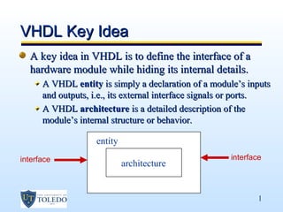
  • 1. VHDL Key Idea A key idea in VHDL is to define the interface of a hardware module while hiding its internal details. A VHDL entity is simply a declaration of a module’s inputs and outputs, i.e., its external interface signals or ports. A VHDL architecture is a detailed description of the module’s internal structure or behavior. entity interface interface architecture 1
  • 2. VHDL Interface - Ports You can think of the entity as a “wrapper” for the architecture hiding the details of what’s inside providing “ports” to other modules entity . . . . input port . architecture . output port 2
  • 3. VHDL Conceptual Model VHDL actually allows you entity to define multiple architectures for a single architecture 1 entity it also provides a configuration management architecture 2 facility that allows you to specify which architecture to use during a particular configuration synthesis run 3
  • 4. VHDL Program File In the text file of a VHDL mydesign.vhd program: the entity, architecture, and entity configuration declarations are all separated architecture not nested as the previous diagram may have implied We will use white space to configuration set them apart 4
  • 5. VHDL Program File In large projects the entities and architectures are sometimes defined in separate files, which the compiler matches according to their declared names VHDL ignores spaces and line breaks Comments begin with two hyphens (--) and end at the end of a line VHDL defines many special character strings, called reserved words or keywords 5
  • 6. VHDL reserved words or keywords Some reserved words or keywords entity, port, is, in, out, end, architecture, begin, when, else, not, etc. 6
  • 7. Elements of VHDL Syntax (the rules) Five design units (or elements) Identifiers (naming constraints) Data objects (what you name) Data types (enumerated, integer, arrays, etc.) Examples 7
  • 8. VHDL Provides Five Design Units Entity Declaration Specifies the NAME and lists the interface PORTS Our initial Architecture Body examples will Models the actual circuit “guts” within an entity focus on the Configuration Declaration first three Identifies which arch. should be used with an entity design units. Specifies location of components used within arch. Package Declaration – like a header file in C Package Body – like an implementation file in C Packages are libraries containing type definitions, overloaded operators, components, functions, and procedures. They have a “declarative” section and a BODY section. Elements of a Package can be used by many entities in a design, or many designs. 8
  • 9. VHDL Identifiers (Names) Basic identifier starts with a letter made up of letters, numbers, and underscore “_” character cannot end with an underscore an underscore cannot follow an underscore case-insensitive: MY_Signal_Name = my_signal_name Extended Identifier not recommended any text within 2 backslashes e.g., 2FOR$ -23signal etc. case is significant: COUNT not equal to count, and FRAMUS not equal to basic identifier FRAMUS Not often used – not necessarily supported in synthesis !! 9
  • 10. VHDL Identifiers (Names) Identifiers in the example half_adder, A, B, BIT, SUM and CARRY BIT is a built-in identifier for a predefined type; and not considered as a reserved word because it can be redefined 10
  • 11. Four Classes of Data Objects Constant Holds a single value of a given type – cannot change. Variable Holds a single value of a given type. New value of same type can be “assigned” – (instantly) Signal analogous to a “wire” Holds a LIST of values of a given type. Present value + a set of possible future values New values can be assigned at some future time – not now! Signals have ATTRIBUTES: [signal’attribute] File Contains a sequence of values of one or more types. Usually read or written to using procedures For simulation – not synthesis 11
  • 12. Data Types Scalar Types Enumerated : a list of values Integer Floating Point Physical : with units, for physical quantities Composite Types Array (all of same type) Record (can be different types) Access Type File Type 12
  • 13. Entity Declaration Specifies the name of the entity Lists the set of interface PORTS PORTS are SIGNALS that enter or leave the entity This is the “black box,” or block diagram view A SUM Half-Adder B CARRY 13
  • 14. Syntax of a VHDL entity declaration entity entity-name is port( signal-names : mode signal-type; signal-names : mode signal-type; … signal-names : mode signal-type); end entity-name; entity-name A user selected identifier signal-names A comma separated list of 1 or more user selected identifiers mode One of the four reserved words signal-type A built in or user defined signal type 14
  • 15. Entity Declaration entity half_adder is port( A, B : in BIT; SUM, CARRY : out BIT); end half_adder; MODE White space is ignored entity half_adder is port( NAME A, B : in BIT; TYPE SUM : out BIT; end of port statement CARRY : out BIT ); end entity half_adder; no “;” after last signal optional words, but recommended 15
  • 16. VHDL Signal Modes in – means input-ONLY, you cannot use a mode in signal on the LEFT side of an equation (that is, you can’t assign a new value to inputs) out – means output-ONLY, you cannot use a mode out signal on the RIGHT side of an equation (that is, you can’t “use” the outputs) inout – means bi-directional, like a three-state bus, for example. This mode is typically used for three-state input/output pins on PLDs buffer – means the signal is an output of the entity, and its value can also be read inside the entity’s architecture 16
  • 17. Entity Declaration entity half_adder is port( A, B : in BIT; SUM, CARRY : out std_logic); end half_adder; Using IEEE 1164 standard signals and data types: entity half_adder is port( A, B : in std_logic; TYPE SUM : out std_logic; CARRY : out std_logic ); end entity half_adder; 17
  • 18. Example: LogicFcn ports A B C Y entity architecture 18
  • 19. Entity Declaration for LogicFcn library IEEE; use IEEE.std_logic_1164.all; entity LogicFcn is port ( A A: in std_logic; B Y B: in std_logic; C C: in std_logic; Y: out std_logic ); end entity LogicFcn; 19
  • 20. Architecture definition An entity’s ports and their modes and types are all that is seen by other modules that use it The entity’s internal operation is specified in it’s architecture definition whose general syntax is as shown next The entity-name in this definition must be the same as the one given previously in the entity declaration The architecture-name is a user selected identifier, usually related to the entity-name; it can be the same as the entity name if desired 20
  • 21. Architecture definition An architecture’s external interface signals (ports) are inherited from the port-declaration part of its corresponding entity declaration An architecture may include signals and other declarations that are local to that architecture Declaration common to multiple entities can be made in a separate “package” used by all entities Declarations can appear in any order 21
  • 22. Syntax:VHDL architecture architecture arch-name of entity-name is type declarations signal declarations named wires constant declarations function definitions procedure definitions later component declarations begin concurrent-statements end arch-name; 22
  • 23. Signal declaration It gives the same information about a signal as in a port declaration, except that no mode is specified: signal signal-names : signal-type; Zero or more signals can be defined within an architecture, and they roughly correspond to named wires in a logic diagram They can be read or written within the architecture definition and, like other local objects, can be referenced only within the encompassing architecture definition 23
  • 24. Variable declaration VHDL variables are similar to signals, except that they usually don’t have physical significance in a circuit Variables are used in VHDL functions, procedures and processes Within these program elements, the syntax of a variable declaration is just like that of a signal declaration, except that the variable keyword is used variable variable-names : variable-type; 24
  • 25. Types and Constants All signals, variables and constants in aVHDL program must have an associated “type” The type specifies the set of range of values that the object can take on, and there is also typically a set of operators (such as add, AND, and so on ) associated with a given type VHDL has just a few predefined types bit, character, severity_level, bit_vector, integer, string, boolean, real, time 25
  • 26. Types and Constants The only ones we’ll see here are integer, character, and boolean The built-in types bit and bit_vector may seem to be essential in digital design, but the “user- defined” types std_logic and std_logic_vector are more useful (IEEE 1164 std) 26
  • 27. Type integers All implementations support 32-bit integers, with a range of values from –(231 – 1) to +(231 – 1) Integer data types with a smaller range can be defined to save hardware (no sense forcing a 32-bit counter when you need a 4-bit counter) Examples of legal integers 56349 6E2 0 98_71_28 (Underscores can be thrown in anywhere, and don’t change the value of the number.) 27
  • 28. Integer Operators VHDL provides the following predefined basic integer operators: Keyword Definition + addition - subtraction * multiplication / division mod Modulo division rem Modulo remainder abs Absolute value ** exponentiation 28
  • 29. Enumerated Types The most commonly used types in typical VHDL programs are user-defined types and the most common of these are enumerated types, which are defined by listing their values Predefined types character and boolean are enumerated types CHARACTER – one of the ASCII set BOOLEAN – can be FALSE or TRUE Built-in operators for boolean type are listed next 29
  • 30. Boolean Operators VHDL provides the following predefined basic boolean operators: Keyword Definition and conjunction or inclusive or xor exclusive or xnor* complement exclusive or nand complement conjunction nor complement inclusive or not complement * only predefined in VHDL-93 30
  • 31. Enumerated Types A type declaration for an enumerated type has the format shown below The value list is a comma-separated list (enumeration) of all possible values of the type The values may be user-defined identifiers or characters Syntax type type-name is (value-list); subtype subtype-name is type-name start to end; subtype subtype-name is type-name start downto end; 31