Suche senden
Hochladen
How to Read a Truss Plan
•
4 gefällt mir
•
15,539 views
W
Western-Building-Center
Folgen
Einzelhandel
Melden
Teilen
Melden
Teilen
1 von 4
Jetzt herunterladen
Downloaden Sie, um offline zu lesen
Empfohlen
Detailed design of portal frames
karan prabhakar
Etabs (atkins)
Etabs (atkins)
Albert deGuzman
L- beams or flanged beams
honeysid
Design of reinforced concrete beam
civilengineeringfreedownload
ACI 318-19 Ingles.pdf
fjimmy
Gantry Girder Design.pptx
neeraj dubey
Slabs -Design steps
Slabs -Design steps
rohinibjn
Is 1893-part2-2014
Is 1893-part2-2014
shankar kumar
Deflection
Deflection
Shivendra Nandan
3 analysis
3 analysis
Mr Patrick NIYISHAKA
CE 72.52 - Lecture6 - Member Behavior
Fawad Najam
Classification based on structure
danappadharwad
Concrete shear wall design
aj aj
Tower design using etabs- Nada Zarrak
Nada Zarrak
Calculation of blast loads
jeyanthi4
Civil engineering - thumb rule
BenAdem1
Reinforced concrete beams
Shivkumar Yadav
Steel design-examples
Faisal Amin
Design of tension members
Sabna Thilakan
DESIGN OF FLAT SLABS
sharda university
6 portal frames
6 portal frames
Prabhu mk
CSI ETABS & SAFE MANUAL: Slab Analysis and Design to EC2
Eur Ing Valentinos Neophytou BEng (Hons), MSc, CEng MICE
Lecture 12 equivalent frame method
alialhussainawi
Lecture_No_1 (Steel structures) (2).pdf
WaliEdwardian1
Design of concrete structures-Nilson-15th-Edition
Bahzad5
Some basics of Strength Of Materials..
Mohammed Mubeen
COMPOSITE BEAMS.pdf
COMPOSITE BEAMS.pdf
Zeinab Awada
Etabs example-rc building seismic load response-
Bhaskar Alapati
State Wall Panel Brochure
Western-Building-Center
Dutch Quaility Stone 2013 Catalog
Western-Building-Center
Weitere ähnliche Inhalte
Was ist angesagt?
Deflection
Deflection
Shivendra Nandan
3 analysis
3 analysis
Mr Patrick NIYISHAKA
CE 72.52 - Lecture6 - Member Behavior
Fawad Najam
Classification based on structure
danappadharwad
Concrete shear wall design
aj aj
Tower design using etabs- Nada Zarrak
Nada Zarrak
Calculation of blast loads
jeyanthi4
Civil engineering - thumb rule
BenAdem1
Reinforced concrete beams
Shivkumar Yadav
Steel design-examples
Faisal Amin
Design of tension members
Sabna Thilakan
DESIGN OF FLAT SLABS
sharda university
6 portal frames
6 portal frames
Prabhu mk
CSI ETABS & SAFE MANUAL: Slab Analysis and Design to EC2
Eur Ing Valentinos Neophytou BEng (Hons), MSc, CEng MICE
Lecture 12 equivalent frame method
alialhussainawi
Lecture_No_1 (Steel structures) (2).pdf
WaliEdwardian1
Design of concrete structures-Nilson-15th-Edition
Bahzad5
Some basics of Strength Of Materials..
Mohammed Mubeen
COMPOSITE BEAMS.pdf
COMPOSITE BEAMS.pdf
Zeinab Awada
Etabs example-rc building seismic load response-
Bhaskar Alapati
Was ist angesagt?
(20)
Deflection
Deflection
3 analysis
3 analysis
CE 72.52 - Lecture6 - Member Behavior
Classification based on structure
Concrete shear wall design
Tower design using etabs- Nada Zarrak
Calculation of blast loads
Civil engineering - thumb rule
Reinforced concrete beams
Steel design-examples
Design of tension members
DESIGN OF FLAT SLABS
6 portal frames
6 portal frames
CSI ETABS & SAFE MANUAL: Slab Analysis and Design to EC2
Lecture 12 equivalent frame method
Lecture_No_1 (Steel structures) (2).pdf
Design of concrete structures-Nilson-15th-Edition
Some basics of Strength Of Materials..
COMPOSITE BEAMS.pdf
COMPOSITE BEAMS.pdf
Etabs example-rc building seismic load response-
Andere mochten auch
State Wall Panel Brochure
Western-Building-Center
Dutch Quaility Stone 2013 Catalog
Western-Building-Center
2015 Ceiling Fan Catalog
Western-Building-Center
2015 Lighting Catalog
Western-Building-Center
2014 Azek Paver Catalog
Western-Building-Center
Wasp Insulation Blower Sales Brochure
Western-Building-Center
Metal Sales Finishing Touch Line - Siding and Roofing
Western-Building-Center
ASC Skyline Roofing Installation Manual
Western-Building-Center
Fabral SSR Metal Roofing Installation Manual
Western-Building-Center
OrePac Moulding and Millwork Guide
Western-Building-Center
Azek at Home Spring 2015
Western-Building-Center
Metrie Moulding Catalog
Western-Building-Center
IKO Blueprint for Roofing
Western-Building-Center
Alexandria Mouldings Designer's Secrets Booklet
Western-Building-Center
Variabilidad infeccionnosocomial2012
María García
Andere mochten auch
(15)
State Wall Panel Brochure
Dutch Quaility Stone 2013 Catalog
2015 Ceiling Fan Catalog
2015 Lighting Catalog
2014 Azek Paver Catalog
Wasp Insulation Blower Sales Brochure
Metal Sales Finishing Touch Line - Siding and Roofing
ASC Skyline Roofing Installation Manual
Fabral SSR Metal Roofing Installation Manual
OrePac Moulding and Millwork Guide
Azek at Home Spring 2015
Metrie Moulding Catalog
IKO Blueprint for Roofing
Alexandria Mouldings Designer's Secrets Booklet
Variabilidad infeccionnosocomial2012
Ähnlich wie How to Read a Truss Plan
Optimized skid design for compressor packages
dieselpub
Camber design
Camber design
Sushil Dhungana
Reforço de armaduras de betão armado anti punçoamento
CORTARTEC
Div_Syd_detailing_of_reinforcement_in_concrete_structures.pdf
LandelSmith1
Precast Concrete Specifications.doc
Abdallah437436
14251 a ch3
14251 a ch3
Jose Luis Puente Paz
A Critical Review of Flat Slabs under different parameters
IRJET Journal
Design of Beam- RCC Singly Reinforced Beam
SHAZEBALIKHAN1
Ch8 Truss Bridges (Steel Bridges تصميم الكباري المعدنية & Prof. Dr. Metwally ...
Hossam Shafiq II
Cross section analysis and design: Worked examples
Engin Soft-Solutions
Final Report (Steel Bridge Design)
Josia Tannos, EIT
89505650 concrete-beam-and-slab-design-using-prokon
OscarKonzult
Geometric Dimensioning and Tolerancing.pptx
Neha Sharma
Read me stack up copy
Charlie Roscoe
CE4410 Final Design Report
Chase Bowman
Rubber Products Presentation on Bridges
Mansoor Chandio
Chassis design for baja sae
CADmantra Technologies
Engineering science lesson 6 2
Shahid Aaqil
Session 5 design of rcc structural elements PROF YADUNANDAN
Ajit Sabnis
DESIGN OF RCC ELEMENTS SESSION 5 PROF. YADUNANDAN
Ajit Sabnis
Ähnlich wie How to Read a Truss Plan
(20)
Optimized skid design for compressor packages
Camber design
Camber design
Reforço de armaduras de betão armado anti punçoamento
Div_Syd_detailing_of_reinforcement_in_concrete_structures.pdf
Precast Concrete Specifications.doc
14251 a ch3
14251 a ch3
A Critical Review of Flat Slabs under different parameters
Design of Beam- RCC Singly Reinforced Beam
Ch8 Truss Bridges (Steel Bridges تصميم الكباري المعدنية & Prof. Dr. Metwally ...
Cross section analysis and design: Worked examples
Final Report (Steel Bridge Design)
89505650 concrete-beam-and-slab-design-using-prokon
Geometric Dimensioning and Tolerancing.pptx
Read me stack up copy
CE4410 Final Design Report
Rubber Products Presentation on Bridges
Chassis design for baja sae
Engineering science lesson 6 2
Session 5 design of rcc structural elements PROF YADUNANDAN
DESIGN OF RCC ELEMENTS SESSION 5 PROF. YADUNANDAN
Mehr von Western-Building-Center
Channellock Ratchet Flyer
Western-Building-Center
Channellock Tool Book
Western-Building-Center
Tool Book March - June 2016
Western-Building-Center
Delta Catalog 2015
Delta Catalog 2015
Western-Building-Center
Home Impressions Catalog 2015
Western-Building-Center
SawStop Job Site Saw Pricelist
Western-Building-Center
SawStop Job Site Saw Flyer
Western-Building-Center
WBC Barn Special
WBC Barn Special
Western-Building-Center
Medallion Specials 2016
Western-Building-Center
WBC Monthly Specials February 2016
Western-Building-Center
40' x 60' x 16' Pole Barn
Western-Building-Center
30' x 40' x 12' Pole Barn
Western-Building-Center
24' x 24' x 10' Pole Barn
Western-Building-Center
Keeping the Dream Alive
Western-Building-Center
WBC Makita Sale Catalog
Western-Building-Center
Do it Best Outdoor Living Catalog
Western-Building-Center
Do it Best Home Decor Catalog
Western-Building-Center
Fence Brochure
Fence Brochure
Western-Building-Center
Medallion Cash Rewards
Western-Building-Center
Medallion Product Announcement
Western-Building-Center
Mehr von Western-Building-Center
(20)
Channellock Ratchet Flyer
Channellock Tool Book
Tool Book March - June 2016
Delta Catalog 2015
Delta Catalog 2015
Home Impressions Catalog 2015
SawStop Job Site Saw Pricelist
SawStop Job Site Saw Flyer
WBC Barn Special
WBC Barn Special
Medallion Specials 2016
WBC Monthly Specials February 2016
40' x 60' x 16' Pole Barn
30' x 40' x 12' Pole Barn
24' x 24' x 10' Pole Barn
Keeping the Dream Alive
WBC Makita Sale Catalog
Do it Best Outdoor Living Catalog
Do it Best Home Decor Catalog
Fence Brochure
Fence Brochure
Medallion Cash Rewards
Medallion Product Announcement
Kürzlich hochgeladen
Film= Dubai Call Girls O525547819 Call Girls Dubai Whsatapp
kojalkojal131
Indian Call Girl In Dubai #$# O5634O3O18 #$# Dubai Call Girl
AroojKhan71
Top Rated Pune Call Girls Talegaon Dabhade ⟟ 6297143586 ⟟ Call Me For Genuin...
Call Girls in Nagpur High Profile
The 15 Minute Breakdown: 2024 Beauty Marketing Study
Tinuiti
Best VIP Call Girls Noida Sector 55 Call Me: 8448380779
Delhi Call girls
Dubai Call Girls O525547&19 (Asii) Call Girls Dubai
kojalkojal131
Best VIP Call Girls Noida Sector 50 Call Me: 8448380779
Delhi Call girls
Best VIP Call Girls Noida Sector 51 Call Me: 8448380779
Delhi Call girls
The 15 Minute Breakdown: 2024 Beauty Marketing Study
KatherineBishop4
Supermarket Floral Ad Roundup- Week 17 2024.pdf
KarliNelson4
Kürzlich hochgeladen
(10)
Film= Dubai Call Girls O525547819 Call Girls Dubai Whsatapp
Indian Call Girl In Dubai #$# O5634O3O18 #$# Dubai Call Girl
Top Rated Pune Call Girls Talegaon Dabhade ⟟ 6297143586 ⟟ Call Me For Genuin...
The 15 Minute Breakdown: 2024 Beauty Marketing Study
Best VIP Call Girls Noida Sector 55 Call Me: 8448380779
Dubai Call Girls O525547&19 (Asii) Call Girls Dubai
Best VIP Call Girls Noida Sector 50 Call Me: 8448380779
Best VIP Call Girls Noida Sector 51 Call Me: 8448380779
The 15 Minute Breakdown: 2024 Beauty Marketing Study
Supermarket Floral Ad Roundup- Week 17 2024.pdf
How to Read a Truss Plan
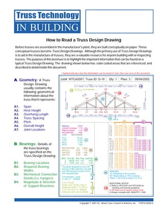
1.
How to Read
a Truss Design Drawing Copyright © 2001-02 Wood Truss Council of America, Inc. TTBTD-020614 Before trusses are assembled in the manufacturer's plant, they are built conceptually on paper. These conceptual trusses become Truss Design Drawings. Although the primary use of Truss Design Drawings is to aid in the manufacture of trusses, they are a valuable resource for anyone building with or inspecting trusses. The purpose of this brochure is to highlight the important information that can be found on a typical Truss Design Drawing. The drawing shown below has color coded areas that are referenced and described in detail inside this document. Truss Technology IN BUILDING AAAAA. Geometry: A Truss Design Drawing usually contains the following geometrical information about the truss that it represents: A1. Span A2. Heel Height A3. Overhang Length A4. Truss Spacing A5. Pitch A6. Overall Height A7. Joint Locations BBBBB. Bearings: Details of the truss bearings are specified on the Truss Design Drawing: B1. Bearing Locations B2. Required Bearing Widths B3. Mechanical Connection Details (i.e. hangers) B4. Magnitude & Direction of Support Reactions Wood Truss Council of America One WTCA Center 6300 Enterprise Lane • Madison, WI 53719 608/274-4849 • 608/274-3329 (fax) www.woodtruss.com • wtca@woodtruss.com Copyright © 2001-02 Wood Truss Council of America, Inc. Reproduction of this document, in any form, is prohibited without written permission from WTCA. This document should appear in more than one color. Truss Technology IN BUILDING An informational series designed to address the issues and questions faced by professionals in the building construction process. JJJJJ. Conditions of Use: The design values used for lumber and plates are dependent upon the conditions under which trusses will be used. For example, if the trusses are expected to function in wet or corrosive conditions, design values will have to be changed accordingly. Any factors that are applied to the design values for lumber and plates are usually stated on the Truss Design Drawings. Truss Installation Tip: Trusses may have symmetrical profiles but the loads they carry may not be symmetrical. Trusses that are mistakenly installed backwards or upside down cannot support the same amount of load as a correctly installed truss. Avoid errors by taking the time to review your Truss Design Drawings. Watch for the following: Is the web configuration symmetrical? If not, check your Truss Design Drawing to see that you have oriented the truss correctly. If the web configuration is symmetrical, are the plates and lumber symmetrical as well? Is the truss carrying any substantial point loads (beams, girders, etc.)? A major point load will usually coincide with the location of a truss joint. Is there a cantilever or interior bearing? If there is, the truss will usually be designed such that the bearing points line up with truss joints. + Symbol indicates that this information can be found in more than one area of this document. BACKWARDS If the truss is designed to be installed this way... DO NOT install this way! UPSIDE DOWN If the truss is designed to be installed this way... DO NOT install this way! +A +EEEEE HHHHH +IIIII JJJJJ +A +GGGGG +DDDDD BBBBB +IIIII +DDDDD +EEEEE +FFFFF CCCCC +IIIII +GGGGG
2.
F2. Combined Stress
Index (CSI): The combined stress index is a ratio of the maximum axial and bending forces expected in a member to the forces that the member should be capable of resisting. It has a maxi- mum value of 1.00 and can be thought of as a measure of structural efficiency. A member with a CSI close to 1.00 is subject to forces approaching its maximum design capacity. GGGGG. Multi-Ply Girder Connection: A girder is a truss that supports loads from other structural members framing into it. The girder may be a single truss or made up of identical trusses attached together to act as one. Multi-ply girder connections ensure that the load is transmitted equally between all plies. Two and three-ply trusses are usually connected using nails. For trusses that are four plies or more, bolts must be used to fasten the plies together. The type of fasteners used, as well as the appropriate pattern and spacing of those fasteners, will be specified on the Truss Design Drawing. HHHHH. Deflection: The maximum deflection of a truss under design load is specified on the design drawing. It is usually shown using two formats. H1. Magnitude & Direction: This is the actual, numerical value of the truss deflection (usually in inches). It assumes positive values for upward deflection and negative values for downward deflection. H2. Deflection Ratio: The deflection ratio is the ratio of the truss span to the maximum expected deflection. For example if a 60' truss deflects 2", the deflection ratio would be L/360 (720" / 2" = 360). Note: Truss deflections are calculated assuming that all truss supports do not contribute to truss deflection. In situations where this is not the case, such as when support is provided by a beam or girder truss, additional deflection should be expected. IIIII. Design Loads: Every Truss Design Drawing must specify the loads that have been accounted for in the design. This includes: I 1. Top chord live loads (may include snow or construction loads) I 2. Top chord dead loads I 3. Bottom chord live loads I 4. Bottom chord dead loads I 5. Controlling wind and earthquake loads The Truss Design Drawing will show specific locations and magnitudes of concentrated or uniform loads applied to girder trusses. Copyright © 2001-02 Wood Truss Council of America, Inc. CCCCC. Lumber: Each drawing specifies the properties of every wood member of the truss. The following information will be shown: C1. Nominal Cross Section Dimensions C2. Lumber Species C3. Lumber Grade DDDDD. Plating Information: Metal plate connected wood trusses are generally designed using proprietary software provided by the manufacturer of the connector plates. As a result, the plate design specified on truss design drawings is only valid for plates supplied by a particular plate manufacturer. For example, it is not acceptable to substitute one brand of plate for another brand of plate unless the substitution is approved by the engineer responsible for the truss design. Most Truss Design Drawings will specify: D1. Plate Manufacturer D2. Size of plate for each joint D3. Gauge of plates (corresponds to thickness) D4. Dimensioned locations of plates EEEEE. Permanent Truss Member Bracing: Individual truss members are often subjected to compression forces. To prevent these members from buckling, permanent truss member bracing is sometimes required. Continuous lateral bracing and T-bracing are common bracing techniques. Required permanent truss member bracing location(s) and/or spacing, will be specified on the design drawing. FFFFF. Truss Member Forces: Truss Design Drawings will specify the maximum axial force expected in each truss member. This information is required for the building designer to specify the details of the permanent continuous lateral bracing. The maximum axial force is usually expressed in two formats: F1. Magnitude & Direction: This is the actual, numerical value of the truss member axial force (usually in pounds). It assumes positive values for members in tension and negative values for members in compression. Note: Dimensioned plate locations are sometimes omitted when a plate is to be positioned symmetrically about a joint interface. Copyright © 2001-02 Wood Truss Council of America, Inc. See WTCA’s TTB Web Member Permanent Bracing and TTB T-Bracing, for more detailed information.
3.
F2. Combined Stress
Index (CSI): The combined stress index is a ratio of the maximum axial and bending forces expected in a member to the forces that the member should be capable of resisting. It has a maxi- mum value of 1.00 and can be thought of as a measure of structural efficiency. A member with a CSI close to 1.00 is subject to forces approaching its maximum design capacity. GGGGG. Multi-Ply Girder Connection: A girder is a truss that supports loads from other structural members framing into it. The girder may be a single truss or made up of identical trusses attached together to act as one. Multi-ply girder connections ensure that the load is transmitted equally between all plies. Two and three-ply trusses are usually connected using nails. For trusses that are four plies or more, bolts must be used to fasten the plies together. The type of fasteners used, as well as the appropriate pattern and spacing of those fasteners, will be specified on the Truss Design Drawing. HHHHH. Deflection: The maximum deflection of a truss under design load is specified on the design drawing. It is usually shown using two formats. H1. Magnitude & Direction: This is the actual, numerical value of the truss deflection (usually in inches). It assumes positive values for upward deflection and negative values for downward deflection. H2. Deflection Ratio: The deflection ratio is the ratio of the truss span to the maximum expected deflection. For example if a 60' truss deflects 2", the deflection ratio would be L/360 (720" / 2" = 360). Note: Truss deflections are calculated assuming that all truss supports do not contribute to truss deflection. In situations where this is not the case, such as when support is provided by a beam or girder truss, additional deflection should be expected. IIIII. Design Loads: Every Truss Design Drawing must specify the loads that have been accounted for in the design. This includes: I 1. Top chord live loads (may include snow or construction loads) I 2. Top chord dead loads I 3. Bottom chord live loads I 4. Bottom chord dead loads I 5. Controlling wind and earthquake loads The Truss Design Drawing will show specific locations and magnitudes of concentrated or uniform loads applied to girder trusses. Copyright © 2001-02 Wood Truss Council of America, Inc. CCCCC. Lumber: Each drawing specifies the properties of every wood member of the truss. The following information will be shown: C1. Nominal Cross Section Dimensions C2. Lumber Species C3. Lumber Grade DDDDD. Plating Information: Metal plate connected wood trusses are generally designed using proprietary software provided by the manufacturer of the connector plates. As a result, the plate design specified on truss design drawings is only valid for plates supplied by a particular plate manufacturer. For example, it is not acceptable to substitute one brand of plate for another brand of plate unless the substitution is approved by the engineer responsible for the truss design. Most Truss Design Drawings will specify: D1. Plate Manufacturer D2. Size of plate for each joint D3. Gauge of plates (corresponds to thickness) D4. Dimensioned locations of plates EEEEE. Permanent Truss Member Bracing: Individual truss members are often subjected to compression forces. To prevent these members from buckling, permanent truss member bracing is sometimes required. Continuous lateral bracing and T-bracing are common bracing techniques. Required permanent truss member bracing location(s) and/or spacing, will be specified on the design drawing. FFFFF. Truss Member Forces: Truss Design Drawings will specify the maximum axial force expected in each truss member. This information is required for the building designer to specify the details of the permanent continuous lateral bracing. The maximum axial force is usually expressed in two formats: F1. Magnitude & Direction: This is the actual, numerical value of the truss member axial force (usually in pounds). It assumes positive values for members in tension and negative values for members in compression. Note: Dimensioned plate locations are sometimes omitted when a plate is to be positioned symmetrically about a joint interface. Copyright © 2001-02 Wood Truss Council of America, Inc. See WTCA’s TTB Web Member Permanent Bracing and TTB T-Bracing, for more detailed information.
4.
How to Read
a Truss Design Drawing Copyright © 2001-02 Wood Truss Council of America, Inc. TTBTD-020614 Before trusses are assembled in the manufacturer's plant, they are built conceptually on paper. These conceptual trusses become Truss Design Drawings. Although the primary use of Truss Design Drawings is to aid in the manufacture of trusses, they are a valuable resource for anyone building with or inspecting trusses. The purpose of this brochure is to highlight the important information that can be found on a typical Truss Design Drawing. The drawing shown below has color coded areas that are referenced and described in detail inside this document. Truss Technology IN BUILDING AAAAA. Geometry: A Truss Design Drawing usually contains the following geometrical information about the truss that it represents: A1. Span A2. Heel Height A3. Overhang Length A4. Truss Spacing A5. Pitch A6. Overall Height A7. Joint Locations BBBBB. Bearings: Details of the truss bearings are specified on the Truss Design Drawing: B1. Bearing Locations B2. Required Bearing Widths B3. Mechanical Connection Details (i.e. hangers) B4. Magnitude & Direction of Support Reactions Wood Truss Council of America One WTCA Center 6300 Enterprise Lane • Madison, WI 53719 608/274-4849 • 608/274-3329 (fax) www.woodtruss.com • wtca@woodtruss.com Copyright © 2001-02 Wood Truss Council of America, Inc. Reproduction of this document, in any form, is prohibited without written permission from WTCA. This document should appear in more than one color. Truss Technology IN BUILDING An informational series designed to address the issues and questions faced by professionals in the building construction process. JJJJJ. Conditions of Use: The design values used for lumber and plates are dependent upon the conditions under which trusses will be used. For example, if the trusses are expected to function in wet or corrosive conditions, design values will have to be changed accordingly. Any factors that are applied to the design values for lumber and plates are usually stated on the Truss Design Drawings. Truss Installation Tip: Trusses may have symmetrical profiles but the loads they carry may not be symmetrical. Trusses that are mistakenly installed backwards or upside down cannot support the same amount of load as a correctly installed truss. Avoid errors by taking the time to review your Truss Design Drawings. Watch for the following: Is the web configuration symmetrical? If not, check your Truss Design Drawing to see that you have oriented the truss correctly. If the web configuration is symmetrical, are the plates and lumber symmetrical as well? Is the truss carrying any substantial point loads (beams, girders, etc.)? A major point load will usually coincide with the location of a truss joint. Is there a cantilever or interior bearing? If there is, the truss will usually be designed such that the bearing points line up with truss joints. + Symbol indicates that this information can be found in more than one area of this document. BACKWARDS If the truss is designed to be installed this way... DO NOT install this way! UPSIDE DOWN If the truss is designed to be installed this way... DO NOT install this way! +A +EEEEE HHHHH +IIIII JJJJJ +A +GGGGG +DDDDD BBBBB +IIIII +DDDDD +EEEEE +FFFFF CCCCC +IIIII +GGGGG
Jetzt herunterladen