light emitting polymers
•Als PPTX, PDF herunterladen•
17 gefällt mir•21,066 views

new way to display technology...

Empfohlen
Weitere ähnliche Inhalte
Was ist angesagt?
Was ist angesagt? (20)
Andere mochten auch
Andere mochten auch (20)
Ähnlich wie light emitting polymers
Ähnlich wie light emitting polymers (20)
Kürzlich hochgeladen
Kürzlich hochgeladen (20)
light emitting polymers
- 3. WELCOME •
- 4. By VISHNU MOHAN V.M Seminar guides, Athira A.P Divya nateshan
- 5. AGENDA INTRODUCTION HISTORY ABOUT LEP ARCHITECTURE WORKING MARIX DISPLAYS MANUFACTURING TYPES OF PLED COMPARISON WITH LCD ADVANTAGE DISADVANTAGES APPLICATIONS FUTURE SCOPES
- 6. INTRODUCTION LEP or PLED or P OLED Polymer which emits light(EM radiations). Polymers are chains of smaller molecular components called MONOMERS. CDT & UDC are developing LEP display.
- 7. HISTORY 1977 conducting polymers are discovered. Alan J. Heeger , Alan G. MacDiarmid got Nobel prize From this OLED evolved. In 1990 Friend et al found Electroluminescence in the conducting polymers. Birth of “LIGHT EMITTING POLYMERS”!!!!!!!!!!! Poly phinylene vinylene (PPV) is the first LEP discovered.
- 8. About LEP……….. Electroluminescence is the principle behind the LEP. LEP comes under the category of conjugated polymers. Polymers with metallic and semiconductor characteristics. Delocalized pi electrons Band gap ranges from 2.2 to 2.8 ev Wave length depends on the band gap of LEP.
- 9. Thin film of semiconducting polymer sandwiched between an ANODE and CATHODE. Metal Cathode Polymer ANODE: ITO(Indium Tin Oxide) CATHODE: Metals (depends upon the type of LEP) Glass Substrate SUBSTRATE: Glass, clear plastic (depends upon the type of LEP) Transparent Anode (ITO) Voltage is applied between anode and cathode
- 10. Due to applied voltage electrons and holes will migrate to polymer lattice. They will combine together to form excitons Excitons returns to initial state by emitting radiation.
- 12. MATRIX DISPLAYS PLED displays consists of matrix of pixels. Each pixel is a light emitting polymer. Emit light by turning OFF and ON the pixels. Primary color pixels are positioned very close to form other colored pixels To control each pixel DRIVERS are needed. DRIVERS are Transistors • 2 matrix
- 13. TWO TYPES OF MATRIX DISPLAY SYSTEMS PASSIVE MATRIX DISPLAYS ACTIVE MATRIX DISPLAYS
- 14. PASSIVE MATRIX DISPLAY Each row and column have its own drivers. The organic layer is between strips of cathode and anode. Intersection forms the Pixel. Matrix scan every pixel to switched on or off as required. Data signal is send to the pixel sequentially. If brightness is to increase, current through that electrode will be increased.
- 15. Passive matrix displays…… Easy to make. Use more power. If size of display increases..it will become difficult. Each pixel only emits light for a small length of time. Flickering is more. Only for small displays.
- 16. ACTIVE MATRIX DISPLAYS Each pixel is addressed by incorporating a TFT. Brightness of each pixel is controlled by TFT. TFT will hold the current. Current flow is controlled by setting TFT drivers. More efficient than passive matrix displays. Can be used in large area displays. AMOLEP or AMOLED
- 17. HOW IT IS MADE………………………………….?
- 18. • Substrate is placed on spinning STEP 1 plate. • Plate is spinning at a speed of few thousand rotation per STEP 2 minute. • Robotic arm will pour small amount of polymer solution to STEP 3 the substrate. • After spreading ,it is baked to STEP 4 evaporate any remaining liquid. • Extremely fine layer of polymers having a thickness of about STEP 5 100nm
- 19. Ink-jet head, Ink and substrate for printing are different Primary colour polymers are jetted to the substrate. Uniformly spread the substrate. Mainly used for printing LEP images. Also used for making large display.
- 20. TYPES OF LEP……….(PLED) Flexible Organic Light Emitting Polymers(FOLEP). Stacked Organic Light Emitting Polymers(SOLEP) Transparent Organic Light Emitting Polymers(TOLEP)
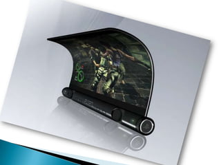
- 21. FLEXIBLE ORGANIC LEP(FOLEP) Built on a flexible substrate. They have the ability to conform, bend or roll a display into any shape. They are less fragile and more impact resistant. Ultra lightweight & thin form.
- 23. TRANSPARENT ORGANIC LEP(TOLEP) Substrate is transparent. LEPs sandwiched between 2 transparent layers. Top and bottom emitting layers. High resolution. More than 70% transparent when turned off. Better efficiency. Faster response.
- 25. STACKED ORGANIC LEP(SOLEP) Array of vertically stacked TOLEP sub-pixels. Color is tuned by individually controlling R-G-B sub pixels Brightness is adjusted by adjusting the total current in the stack. It will only turn on the desired color pixel only. Can be used in large displays True color quality.
- 26. Screen Refreshing Rates Higher than LCD Viewing quality Higher than LCD Screen size Size is not limited in LEP display Viewing angle Glare free up to 170 degree Power consumption Lesser than LCD
- 27. ADVANTAGES….. Require only 3.3v & life time of more than 30,000 hr. Low power consumption. Self luminous. No viewing angle dependence. Manufacturing cost is less. Can be scaled to any dimension. No environmental draw backs. Simple to use. Very slim flat panel displays.
- 28. DISADVANTAGES…… Voltage drops may affect the performance. Limited market availability. Aging of LEP Degradation of luminescence Light intensity gradually decreases. Disintegrate due to contact with oxygen.
- 29. APPLICATIONS…… Multi or full color cell phone displays Full color high-resolution personal digital assistants(PDAs) Lightweight wrist watches Roll-up daily refreshable electronic newspapers Automobile light systems without bulbs
- 30. FUTURE SCOPES…. LEP-in future cars
- 31. LAPTOPS……
- 32. TELEVISIONS…
- 33. Have both electrical and optical property A low cost solution for flat panel display. Many manufactures are working to introduce a revolutionary changes in the market. Hazardless to environment. Simpler and cheaper Have some limitations Till it is the superior technology………for the future…..