Sketching With SolidWorks
•
3 gefällt mir•2,441 views

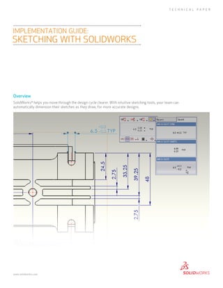
SolidWorks® helps you move through the design cycle clearer. With intuitive sketching tools, your team can automatically dimension their sketches as they draw, for more accurate designs.

Empfohlen
Weitere ähnliche Inhalte
Was ist angesagt?
Was ist angesagt? (20)
Ähnlich wie Sketching With SolidWorks
Ähnlich wie Sketching With SolidWorks (20)
Mehr von SOLIDWORKS
Mehr von SOLIDWORKS (17)
Kürzlich hochgeladen
Kürzlich hochgeladen (20)
Sketching With SolidWorks
- 1. Overview SolidWorks® helps you move through the design cycle clearer. With intuitive sketching tools, your team can automatically dimension their sketches as they draw, for more accurate designs. implementation guide: sketching with SolidWorks TECHNICAL PAPER www.solidworks.com
- 2. Sketching in SolidWorks is the basis for creating features. Features are the basis for creating parts, which can be put together into assemblies. Sketch entities can also be added to drawings. SolidWorks features contain intelligence so they can be edited. Design intent is an important consideration when creating SolidWorks models, so planning when sketching is important. The general procedure for sketching is to: 1. In a part document, select a sketch plane or a planar face, (You can do this either before or after step 2.) 2. Enter the Sketch mode by doing one of the following: • Click Sketch on the Sketch toolbar. • Click a sketch tool (Rectangle, for example) on the Sketch toolbar. • Click Extruded Boss/Base or Revolved Boss/Base on the Features toolbar. • Right-click an existing sketch in the FeatureManager design tree and select Edit Sketch. 3. Create the sketch (sketch entities such as lines, rectangles, circles, splines, and so on). 4. Add dimensions and relations (you can sketch approximately, then dimension exactly). 5. Create the feature (which closes the sketch). In general, it is better to use less complicated sketch geometry and more features. Simpler sketches are easier to create, dimension, maintain, modify, and understand. Models rebuild faster with simpler sketches. Sketch Dimensions You can create features without adding dimensions to sketches. However, it is good practice to dimension sketches. Dimension in accordance with the model’s design intent; for example, you might want to dimension holes a certain distance from an edge, or a certain distance from each other. To place a hole a specified distance from the edges of a block, dimension the diameter of the circle and dimension the distance between its center and each edge of the block. Circles are measured from the center by default. Sketching in SolidWorks is the basis for creating features 2 | Implementation Guide: Sketching with SolidWorks | www.solidworks.com
- 3. To place a hole a specified distance from the edges of a block, dimension the diameter of the circle and dimension the distance between its center and each edge of the block. Circles are measured from the center by default. Most dimensions (linear, circular, or angular) can be inserted using a single tool, Smart Dimension on the Dimensions/Relations toolbar. Additional dimension tools (Baseline, Ordinate, Chamfer) are available on the Dimensions/Relations toolbar. You can dimension all entities in a sketch in one operation with Fully Define Sketch. To change dimensions, double-click the dimension and edit the value in the Modify dialog box, or drag a sketch entity. snap SolidWorks sketch entities can snap to points (endpoint, midpoints, intersections, and so on) of other sketch entities. With Quick Snaps, you can filter the types of sketch snaps that are available. Additional snap functionality includes: • Grid (displayed and snapped to) • Inferencing (relations displayed as you sketch) • Relations (added between sketch entities automatically through inferencing or manually) 3 | Implementation Guide: Sketching with SolidWorks | www.solidworks.com
- 4. Sketch Relations In SolidWorks, relations between sketch entities and model geometry are an important means of building in design intent. For example, you can draw two concentric circles. If you specify a concentric relation and then move one circle, the other circle moves with it, maintaining the relation. You can add relations in the following ways: • Automatically by SolidWorks during sketching. The cursor changes to inform you of the relation it is inferencing. • Manually after creating the sketch entities when you open entity PropertyManagers or the Add Relations PropertyManager. You can also Display and Delete Relations. To place a hole in the center of the block, sketch a centerline from corner to corner, then specify a Midpoint relation between the center of the circle and the centerline. 1. The inferencing line shows a vertical relation between the endpoints of the two lines. 2. The in the pointer display indicates that the line being sketched is horizontal. The horizontal relation is added to the entity properties automatically. The two circles are specified to be concentric. When you move one, the other moves with it. In SolidWorks, relations between sketch entities and model geometry are an important means of building in design intent 4 | Implementation Guide: Sketching with SolidWorks | www.solidworks.com
- 5. Inferencing Inferencing displays relations by means of dotted inferencing lines, pointer display, and highlighted cues such as endpoints and midpoints. Inferencing lines Inferencing lines appear as you sketch, displaying relations between the pointer and existing sketch entities (or model geometry). Pointer display The pointer display indicates when the pointer is over a geometric relation (an intersection, for example), what tool is active (line or circle), and dimensions (angle and radius of an arc). If the pointer displays a relation (such as for a horizontal relation) and you click to accept the sketch entity while the relation is displayed, the relation is added automatically to the entity. NOTE: You can turn off automatic relations. Click Tools, Sketch Settings, Automatic Relations. Highlighted cues Geometric relations such as endpoints, midpoints, and vertices highlight when the pointer approaches them, then change color when the pointer is poised to select them. On the left, a midpoint highlights and the pointer shows that a coincident relation is possible at its current position. On the right, the midpoint has changed color and the pointer shows that it recognizes the midpoint . 5 | Implementation Guide: Sketching with SolidWorks | www.solidworks.com The pointer display indicates when the pointer is over a geometric relation (an intersection, for example)
- 6. trim You can trim sketch entities, including infinite lines, and extend sketch entities (lines, centerlines, and arcs) to meet other entities. Trim Entities includes options: • Power trim. Trim multiple adjacent sketch entities by dragging the pointer across the entities, or extend entities by selecting them and dragging the pointer. • Corner. Trim or extend two sketch entities until they intersect at a virtual corner. • Trim away inside. Trim open sketch entities inside two bounding entities. • Trim away outside. Trim open sketch entities outside two bounding entities. • Trim to closest. Trim or extend sketch entities to the closest intersection. Sketch States Sketches are generally in one of the following states: • Under defined • Fully defined • Over defined The sketch status appears in the window status bar. Colors indicate the state of individual sketch entities. Under defined. As you begin a sketch, you can drag the entities to change their shape or position. In this rectangle, the black left and bottom lines are fixed to the origin, but you can drag the top and right lines. Blue indicates that the entity is not fixed, and light blue indicates that the entity is selected. To add relations to a sketch, click Add Relations on the Dimensions/ Relations toolbar. Fully defined. Adding dimensions to the top and right fixes the sizes of all the sides of the rectangle because of the implied equal relations between the top and bottom and the two sides. The rectangle itself is fixed to the origin. All the entitie turn black, indicating that the rectangle is fully defined. 6 | Implementation Guide: Sketching with SolidWorks | www.solidworks.com As you begin a sketch, you can drag the entities to change their shape or position
- 7. You can add relations (parallel, perpendicular, equal length, and so on) to a fully defined sketch. The sketch tolerates these logically redundant relations. Over defined. Redundant dimensions over define a sketch. The red rectangle is over defined. When you insert dimensions, they are assumed to be driving dimensions. To have two dimensions driving the same geometry is invalid. A dialog box appears allowing you to designate the redundant dimension as driven. You can view and delete relations. Click Display/Delete Relations on the Dimensions/Relations toolbar. It is possible to create geometry that is unsolvable or invalid. The items that prevent the solution are displayed in pink (unsolvable) or yellow (invalid). Sketches with these types of geometry are labeled No Solution Found or Invalid Solution Found. Dimensions and relations are two types of constraints. You define sketches with either type, or both. Although you can create features using sketches that are not fully defined, it is a good idea to fully define sketches for production models. Sketches are parametric, and if they are fully defined, changes are predictable. However, sketches in drawings, although they follow the same conventions as sketches in parts, do not need to be fully defined since they are not the basis of features. Automatic Sketch Operations Automatic operations increase productivity in sketching. Automatic relations and inferencing also improve efficiency in sketching. You can dimension all entities or selected entities in a sketch, including model edges, with the Fully Define Sketch tool on the Dimensions/Relations toolbar. You can solve over defined sketches using SketchXpert, which cycles through potential solutions. You can add relations (parallel, perpendicular, equal length, and so on) to a fully defined sketch 7 | Implementation Guide: Sketching with SolidWorks | www.solidworks.com
- 8. You can transition automatically from line to tangent arc and back, so you can create sketches like this without changing tools. You can convert raster data to vector data using auto trace tools. You can highlight and activate planar faces or planes to quickly create sketches using RapidSketch. 8 | Implementation Guide: Sketching with SolidWorks | www.solidworks.com
- 9. Construction Entities In SolidWorks, any sketch entity can be specified for construction. Points and centerlines are always construction entities only. Use a centerline as the axis about which a sketch revolves to create a base feature, or to mirror sketch entities. SolidWorks also has Reference Geometry (planes, axes, and coordinate systems) as a basis for creating features outside of sketches. Use planes to construct a series of sketches as the basis or a loft feature. With simple click and drag sketching from SolidWorks, designing is more accurate so you can design better products faster. Additional ideas and help are available on the SolidWorks web site at www.solidworks.com. SolidWorks is a registered trademark of Dassault Systèmes SolidWorks Corp. All other company and product names are trademarks or registered trademarks of their respective owners. ©2011 Dassault Systèmes. All rights reserved. MKsketchTpENG0611 Dassault Systèmes SolidWorks Corp. 300 Baker Avenue Concord, MA 01742 USA Phone: 1 800 693 9000 Outside the US: +1 978 371 5011 Email: info@solidworks.com www.solidworks.com