Interactive Powerpoint_How to Master effective communication
Lm35
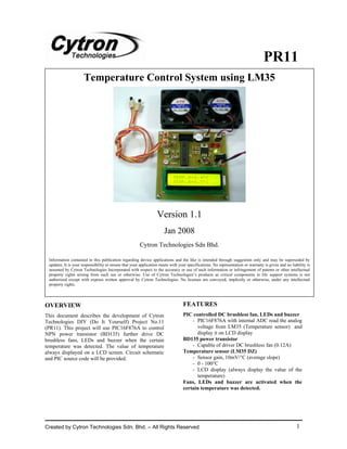
1. PR11
Temperature Control System using LM35
Version 1.1
Jan 2008
Cytron Technologies Sdn Bhd.
Information contained in this publication regarding device applications and the like is intended through suggestion only and may be superseded by
updates. It is your responsibility to ensure that your application meets with your specifications. No representation or warranty is given and no liability is
assumed by Cytron Technologies Incorporated with respect to the accuracy or use of such information or infringement of patents or other intellectual
property rights arising from such use or otherwise. Use of Cytron Technologies’s products as critical components in life support systems is not
authorized except with express written approval by Cytron Technologies. No licenses are conveyed, implicitly or otherwise, under any intellectual
property rights.
OVERVIEW FEATURES
This document describes the development of Cytron PIC controlled DC brushless fan, LEDs and buzzer
Technologies DIY (Do It Yourself) Project No.11 - PIC16F876A with internal ADC read the analog
(PR11). This project will use PIC16F876A to control voltage from LM35 (Temperature sensor) and
NPN power transistor (BD135) further drive DC display it on LCD display
brushless fans, LEDs and buzzer when the certain BD135 power transistor
temperature was detected. The value of temperature - Capable of driver DC brushless fan (0.12A)
always displayed on a LCD screen. Circuit schematic Temperature sensor (LM35 DZ)
and PIC source code will be provided. - Sensor gain, 10mV/°C (average slope)
- 0 - 100°C
- LCD display (always display the value of the
temperature)
Fans, LEDs and buzzer are activated when the
certain temperature was detected.
Created by Cytron Technologies Sdn. Bhd. – All Rights Reserved 1
2. ROBOT . HEAD to TOE
PR11 – Temperature Control System using LM35
SYSTEM OVERVIEW
Temperature
Sensor
LCD
LED Indicator
PIC16F876A
Cooling Fan
Buzzer
GENERAL DESCRIPTION Temperature Sensor (LM35)
PIC has been used to control the LED or buzzer In this project, two LM35s are used for two difference
directly for some previous PRs. But in this project, PIC temperature. Vs of the LM35s are given 5V and the
cannot directly activate the DC brushless fan because it Vout pins are connected to AN0 and AN1
has not enough current. NPN power transistor (BD135) (PIC16F876A) separately.
is required, so that DC brushless fan can be controlled
by PIC. PIC16F876A will read the analog voltage 5V
(using ADC) from LM35 temperature sensor and
display it on LCD display. A buzzer, LEDs or fans will
be activated when temperature reach a certain Connect to PIC (Analog pin)
temperature value.
Power Transistor (BD135)
Figure 2
BD135 is used for controlling the DC brushless fan
with sufficient current. Following Figure 1 shows the Since the sensor gain (average slope) of the LM35
is 10mV / C and ADC has 10 bit ( 2 ≈ 1000 ), so
pin diagram of BD135. o 10
pin 5 (Vref) from PIC16F876A must be given for 1V
by using the voltage divider concept. For preventing
the offset, voltage for pin 5 (Vref) should be adjustable
(using Preset) as shown in Appendix A.
Vs
Vout
GND
Figure 3
Figure 1
Created by Cytron Technologies Sdn. Bhd. – All Rights Reserved 2
3. ROBOT . HEAD to TOE
PR11 – Temperature Control System using LM35
PIC16F876A (Microcontroller) Interface PIC16F876A with Temperature
This powerful (200 nanosecond instruction execution) Sensor (LM35)
yet easy-to-program (only 35 single word instructions) Signal pin (Vout) from LM35 can be connected to
CMOS FLASH-based 8-bit microcontroller packs either one of analog input pin (AN0-AN4) except AN3
Microchip's powerful PIC® architecture into an 28-pin (pin 5) but make sure the ADC configuration is correct
package and is upwards compatible with the according to the Figure 11 (Software section). In fact,
PIC16C5X, PIC12CXXX and PIC16C7X devices. pin 5 (Vref+) from PIC should be given for 1V but it
The PIC16F876A features: may has offset, so a variable resistor (VR1) was
installed for voltage adjusting. For more stability, user
• 256 bytes of EEPROM data memory
is recommended add a capacitor (104) between the
• Self programming
analog signal and GND for every analog input such as
• An ICD signal from LM35 and variable resistor (VR1).
• 2 Comparators
• 5 channels of 10-bit Analog-to-Digital (A/D)
Interface PIC16F876A with LCD (2X16
converter
• 2 capture/compare/PWM functions character)
• The synchronous serial port can be configured LCD used in this project is JHD162A, for other type of
as either 3-wire Serial Peripheral Interface LCD, please refer to its data sheet.
(SPI™) or the 2-wire Inter-Integrated Circuit
(I²C™) bus
• A Universal Asynchronous Receiver
Transmitter (UART)
All of these features make it ideal for more advanced
level A/D applications in automotive, industrial,
appliances and consumer applications.
Figure 5
The 16 header pin should be soldered to the LCD first.
The following table shows the LCD (2X16 character)
connection:
Pin Name Pin function Connection
1 VSS Ground GND
2 VCC Positive supply 5V
for LCD
3 VEE Contrast adjust Connected to
a preset for
Figure 4 contrast
adjusting
Figure 4 shows the pin diagram for PIC16F876A. For 4 RS Select register, RA2
more detail, please download the datasheet from select instruction
microchip web site at: http://www.microchip.com or data register
5 R/W Select read or GND
HARDWARE write
6 E Start data read or RA5
This project will require following hardware: write
a. 1 x PIC16F876A 7 DB0 Data bus pin RC0
b. 1 x PR11 Printed Circuit Board (PCB) 8 DB1 Data bus pin RC1
c. 1 x LCD 9 DB2 Data bus pin RC2
d. 1 x Buzzer 10 DB3 Data bus pin RC3
e. 2 x Temperature Sensor (LM35) 11 DB4 Data bus pin RC4
f. 2 x DC Brushless Fan 12 DB5 Data bus pin RC5
g. Other related electronic components 13 DB6 Data bus pin RC6
14 DB7 Data bus pin RC7
Please refer to the schematic diagram of PR11. The 15 LED+ Backlight positive 5V
schematic is provided free and therefore Cytron input
Technologies will not be responsible for any further 16 LED- Backlight GND
modification or improvement. negative input
Table 1
Created by Cytron Technologies Sdn. Bhd. – All Rights Reserved 3
4. ROBOT . HEAD to TOE
PR11 – Temperature Control System using LM35
Figure 6 shows the schematic of the LCD display. convenience way to load program into PIC
microcontroller without removing the PIC from the
circuit board. So pin 1 (Vpp), pin 27 (PGC) and pin 28
(PGD) from PIC should be connected to Cytron USB
In Circuit Programmer (UIC00A) through the external
cable. Besides, GND from the circuit board also should
be connected with GND from UIC00A and pin 24
(PGM) should be pulled to GND through a 10K
resistor as shown in Figure 8. The programmer
(UIC00A) is not included in DIY project set since it
can be used several times for different project set. User
can also choose other type of PIC programmer to load
the program. Since the ICSP is used, three I/O pins
(RB3, RB6 and RB7) cannot be used as input again but
it still can be used for output.
Figure 6 Push Button as Input for PIC
microcontroller
Power Supply for Circuit
Figure 7
For this project, the voltage range of power source
could be given for this circuit board is between 7V and
15V. Higher input voltage will produce more heat at
LM7805 voltage regulator. Typical voltage is 12V. Figure 9
Anyhow, LM7805 will still generate some heat at 12V. One I/O pin is needed for one push button as input for
There are two type of power connector on the circuit PIC microcontroller. The connection of the push button
board, DC plug ‘Adaptor’ is for AC-DC adaptor and to the I/O pin is shown in Figure 9. The I/O pin should
2510-02 ‘Power’ is for battery source. Normally AC to be pull up to 5V using a resistor (with value range 1K-
DC adaptor can be plugged to ‘Adaptor’ type 10K) and this configuration will result an active-low
connector. LM7805 (1A maximum) will regulate the input. When the button is being pressed, reading of I/O
given voltage to 5V (VCC) for supplying to the pin will be in logic 0, while when the button is not
PIC16F876A and pull-up the push button (input). The pressed, reading of that I/O pin will be logic 1.
purpose of using diode (D1) is for circuit protection in
case the polarity of the power source is incorrect. LED as Output for PIC microcontroller
Capacitor (C5) and capacitor (C1) is use to stabilize the
voltage input and output of the LM7805. DS1 is a
green LED (small) as power indicator.
ICSP for Programming PIC
Microcontroller
Figure 10
Figure 8 One I/O pin is needed for one LED as output for PIC
In Circuit Serial Programming (ICSP) is used for microcontroller. The connection for a LED to I/O pin is
loading program in this project. ICSP gives you a shown in Figure 10. The function of R8 is to protect
Created by Cytron Technologies Sdn. Bhd. – All Rights Reserved 4
5. ROBOT . HEAD to TOE
PR11 – Temperature Control System using LM35
the LED from over current that will burn the LED. Program
When the output is in logic 1, the LED will ON, while
when the output is in logic 0, the LED will OFF. Please download the sample program from Cytron
website (same directory as this DIY project)
Interface PIC16F876A with DC Brushless
The source code is provided free and Cytron
Fan Technologies will not be responsible for any further
Since the current of I/O pin from PIC is limited to modification or improvement.
drive a DC Brushless Fan (0.12A), so Power Transistor
(BD135) is required for giving current to it sufficiently. Analog to Digital Converter (A/D) Module
The maximum collector current, Ic of BD135 is 1.5A,
which means the DC Brushless Fan greater than 1.5A The Analog-to-Digital (A/D) Converter module has
cannot be driven. five inputs for PIC16F876A. The conversion of an
analog input signal results in a corresponding 10-bit
digital number. The A/D module has high and low-
SOFTWARE voltage reference input that is software selectable to
some combination of VDD, VSS, RA2 or RA3.
Flow Chart:
The A/D module has four registers. These registers are:
Start • A/D Result High Register (ADRESH)
• A/D Result Low Register (ADRESL)
• A/D Control Register 0 (ADCON0)
• A/D Control Register 1 (ADCON1)
ADC process to
get analog output
from LM35 The ADCON0 register, shown in Figure 11, controls
the operation of the A/D module. For PR11, clock
conversion Fosc/64 has been selected. Only two
Display 2 different
channels (AN0 &AN1) are used for two temperature
temperatures on LCD sensors separately. ADCON0 should be 0b10000001
for channel 0 and 0b10001001 for channel 1.
The ADCON1 register, shown in Figure 12, configures
Temp A > 40C Yes Fan A & LED A the functions of the port pins. In this project, ADCON1
& activated was set to 0b11000101. Right justified result format
Temp B < 35C?
was selected (ADFM=1) as shown in Figure 14. The
port pins can be configured as analog inputs (RA3 can
No also be the voltage reference) or as digital I/O. 4 Least
Significant bits for ADCON1 were set to 0011, so that
Yes Fan B & LED B the AN0 pin and AN1 pin are configured as analog
Temp A < 40C
& activated input but AN3 is set for Vref as shown in Figure 12.
Temp B > 35C?
The ADRESH:ADRESL registers contain the 10-bit
No result of the A/D conversion. When the A/D
conversion is complete, the result is loaded into this
Fan A & LED A, A/D Result register pair, the GO/DONE bit
Temp A > 40C Yes Fan B & LED B
and buzzer (ADCON0<2>) is cleared and the A/D interrupt flag
&
Temp B > 35C? activated bit ADIF is set. After the A/D module has been
configured as desired, the selected channel must be
acquired before the conversion is started. The analog
No
input channels must have their corresponding TRIS
Fan A & LED bits selected as inputs.
Temp A < 40C Yes A, Fan B &
& LED B and
Temp B < 35C? buzzer
deactivated
No
Created by Cytron Technologies Sdn. Bhd. – All Rights Reserved 5
6. ROBOT . HEAD to TOE
PR11 – Temperature Control System using LM35
ADCON0=0b10000001
ADCS (A/D Conversion
Clock Select Bits) ADON (A/D On Bit)
CHS (Analog Channel Unimplemented
Select bits)
GO/DONE (A/D
Conversion Status Bit)
ADCON1=0b11000101
ADFM (A/D Result PCFG (A/D Port
Format Select Bit) Configuration Control Bits)
ADCS2 (A/D Conversion Unimplemented
Clock Select Bit)
Figure 13
The ADRESH:ADRESL register pair is the location
Figure 11 where the 10-bit A/D result is loaded at the completion
of the A/D conversion. This register pair is 16 bits
wide. The A/D module gives the flexibility to left or
right justify the 10-bit result in the 16-bit result
register. The A/D Format Select bit (ADFM) controls
this justification.
Figure 14 below shows a subroutine how to get the
value from ADC.
Figure 14
Figure 12
Created by Cytron Technologies Sdn. Bhd. – All Rights Reserved 6
7. ROBOT . HEAD to TOE
PR11 – Temperature Control System using LM35
Program Modification Step for soldering 2510 connector:
The program can be modified for the desired 1 2
temperatures to activate the LEDs, fans and buzzer.
The sample program is written as shown below. Just
change temperature value inside the red circle in Figure
15 below:
3 4
5 6
Figure 15
For example, if the desired temperature A is 48°C and 7
temperature B is 55°C, so the value of tempA and
tempB should be 480 and 550 respectively.
GETTING START
User can obtain the hardware set for this project (PR11) Figure 16
either by online purchasing (www.cytron.com.my) or
purchase it in Cytron Technologies Shop. For this project, temperature sensors (LM35) and
1. Once user has the hardware set, soldering cooling fans are connected to the circuit board through
process can be started now. Please solder the some wires and connectors. The length of the wires is
electronic components one by one according various depend on the distance of a certain area where
the symbols or overlays on the Printed Circuit would be measured. Each polarity should be correctly
Board (PCB). Make sure the component value connected! Differentiate the types of the connector and
and polarity is correctly soldered. Please refer please use 2510 connector for LM35 and 2021
to PCB Layout in Appendix A. connector for cooling fan.
Caution: Make sure all the connectors (2510) are 2. After soldering process is finished, please
soldered in proper side. Those electronic plug in the PIC16F876A to the 28 pins IC
components have polarity such as capacitor, socket in proper side. The MPLAB IDE and
diode, PIC, LM7805, LM35, BD135 and LED PICC Lite can be downloading from
should be soldered in right polarity or it may www.cytron.com.my.
cause the circuit board fail to work. 3. After the installation complete, open the
project file provided using MPLAB IDE.
Warning:Before the battery (Power) is plugged in, Please refer to PR1 and PR5 for the method to
make sure the polarity is correct to prevent the use MPLAB and PICC Lite. Please plug in the
explosion. Wrong polarity of capacitor also power supply and connect the programmer
may cause explosion. connector to the circuit board to reprogram the
PIC. Do not forget to ON the slide switch!
User can get the sample program for this
project from Cytron website (same directory
as this DIY project) and this program can be
modified.
4. After modification, build the project and load
the hex file into the PIC microcontroller using
Cytron USB In Circuit Programmer (UIC00A).
Cytron Technologies do offer USB In Circuit
Programmer (UIC00A) as an option in the
Created by Cytron Technologies Sdn. Bhd. – All Rights Reserved 7
8. ROBOT . HEAD to TOE
PR11 – Temperature Control System using LM35
hardware list. Please tick the option if the A and temperature B is over 40.0°C and
programmer is necessary. 35.0°C respectively. The buzzer will turn ON.
5. User can choose either adaptor or battery to
provide the power for the circuit board but WARRANTY
make sure the given voltage is between 7V
and 15V. No warranty will be provided as this is DIY project.
Please check the polarity of each electronic component
AC to DC adaptor: before soldering it to board.
12V Polarity
Figure 17 (not included in DIY project set)
9V battery connector:
Figure 18 (not included in DIY project set)
Connection to the PCB board:
Figure 19
6. When the power is provided, the green LED
(small) will turn ON. Let say the sample
program (without modification) is being used.
7. First, adjust the ‘Contrast’ VR2 for desired
brightness of LCD Display. Voltage of pin 5
(Vref+) from PIC should adjusted to 1V by
rotating the ‘Offset’ VR1 and using a Multi-
meters.
8. If the displayed temperature is different from
real temperature, adjust VR1 again to reduce
the offset. LED A would light if temperature
A reach to 40.0°C.
9. LED B would light to indicate that
temperature B is reach to 35.0°C. Both LEDs
and buzzer would be activated if temperature
Created by Cytron Technologies Sdn. Bhd. – All Rights Reserved 8
9. ROBOT . HEAD to TOE
PR11 – Temperature Control System using LM35
Appendix A
PCB Layout:
2053-02 2053-02
C-cap Connector Connector
2510-03 104 Box
Connector Header
BD135 BD135
Buzzer ECB BCE
2510-03 C-cap
Connector 104 1K
4K7 LED 5mm
1N4148 LM7805
Diode PIC16F876A 220R
Preset C-cap LED 3mm
4K7 30pF 220R
C-cap Adaptor
C-cap 20MHz 104 C-cap socket
104 Crystal E-cap 104
10uF 16V
Preset 1N4007
4K7 Diode 2510-02
Slide Connector
switch
LCD
Prepared by
Cytron Technologies Sdn. Bhd.
19, Jalan Kebudayaan 1A,
Taman Universiti,
81300 Skudai,
Johor, Malaysia.
Tel: +607-521 3178
Fax: +607-521 1861
URL: www.cytron.com.my
Email: support@cytron.com.my
sales@cytron.com.my
Created by Cytron Technologies Sdn. Bhd. – All Rights Reserved 9