8 Channel Analog Data Logger

A data logger (also data logger or data recorder) is an electronic device that records data over time or in relation to location either with a built in instrument or sensor or via external instruments and sensors. Increasingly, but not entirely, they are based on a digital processor (or computer). They generally are small, battery powered, portable, and equipped with a microprocessor, internal memory for data storage, and sensors. Some data loggers interface with a personal computer and utilize software to activate the data logger and view and analyze the collected data, while others have a local interface device (keypad, LCD) and can be used as a stand-alone device. Data loggers vary between general purpose types for a range of measurement applications to very specific devices for measuring in one environment or application type only. It is common for general purpose types to be programmable; however, many remain as static machines with only a limited number or no changeable parameters. Electronic data loggers have replaced chart recorders in many applications.

Empfohlen
Weitere ähnliche Inhalte
Was ist angesagt?
Was ist angesagt? (20)
Andere mochten auch
Andere mochten auch (19)
Ähnlich wie 8 Channel Analog Data Logger
Ähnlich wie 8 Channel Analog Data Logger (20)
Mehr von Raghav Shetty
Mehr von Raghav Shetty (20)
Kürzlich hochgeladen
Kürzlich hochgeladen (20)
8 Channel Analog Data Logger
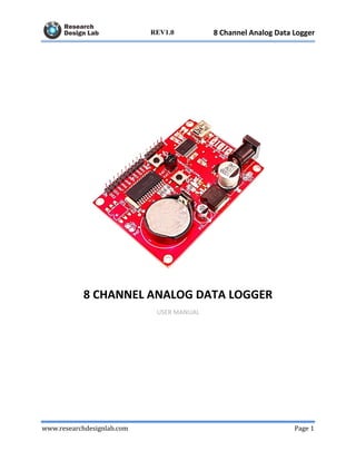
- 1. www.researchdesignlab.com Page 1 8 Channel Analog Data LoggerREV1.0 8 CHANNEL ANALOG DATA LOGGER USER MANUAL
- 2. www.researchdesignlab.com Page 2 8 Channel Analog Data LoggerREV1.0 Contents OVERVIEW ................................................................................................................................... 3 Data Logger ................................................................................................................................ 3 FEATURES .................................................................................................................................... 4 SCHEMATIC OF 8 CHANNEL DATA LOGGER....................................................................... 5 CONNECTION DIAGRAM .......................................................................................................... 6 CONFIGURATION AND MONITORING ................................................................................... 7 Method 1: Using Serial Monitor................................................................................................. 7 Method 2: Using Data logger application (windows)............................................................... 10 Data Logger application........................................................................................................ 10 Screen shots .......................................................................................................................... 11
- 3. www.researchdesignlab.com Page 3 8 Channel Analog Data LoggerREV1.0 OVERVIEW Data Logger A data logger (also data logger or data recorder) is an electronic device that records data over time or in relation to location either with a built in instrument or sensor or via external instruments and sensors. Increasingly, but not entirely, they are based on a digital processor (or computer). They generally are small, battery powered, portable, and equipped with a microprocessor, internal memory for data storage, and sensors. Some data loggers interface with a personal computer and utilize software to activate the data logger and view and analyze the collected data, while others have a local interface device (keypad, LCD) and can be used as a stand-alone device. Data loggers vary between general purpose types for a range of measurement applications to very specific devices for measuring in one environment or application type only. It is common for general purpose types to be programmable; however, many remain as static machines with only a limited number or no changeable parameters. Electronic data loggers have replaced chart recorders in many applications.
- 4. www.researchdesignlab.com Page 4 8 Channel Analog Data LoggerREV1.0 8 Channel Analog Data Logger One of the primary benefits of using data loggers is the ability to automatically collect data on a 24-hour basis. Upon activation, data loggers are typically deployed and left unattended to measure and record information for the duration of the monitoring period. This allows for a comprehensive, accurate picture of the environmental conditions being monitored, such as air temperature and relative humidity, production quantity monitoring, boiler temperature, fuel level, energy consumption etc. It can be used for saving data to files on any FAT formatted SD card, to be read by any plotting, spreadsheet or analysis program. This data logger is standalone configurable timestamp for sec, min, hourly also you can configure the threshold limit for any one channel, when it crosses the threshold limit it will activate the output. This output can be connected to any external driving interface (Relay, valve etc) you can also configure for real time monitoring. FEATURES • 8 Channel Analog Data Logger Features: • 8+1 Channel (8 Channel Analog input Vdc (0-5V)). • 1 output channel triggering the external relay or valve when it crosses the set threshold limit. • RTC DS1307 with inbuilt battery enable • On board SD card socket. • Supports upto 4GB SD CARD –FAT filesystem. • Standard FT232 USB interface for real time monitoring and configuring. • Logged data will be store in .xlsx format. • Power supply 5V. • 8 channel analog input Voltage range 0-5V. • Easy timestamp configuration (sec, min, hr.). • High quality PCB FR4 Grade with FPT Certified.
- 5. www.researchdesignlab.com Page 5 8 Channel Analog Data LoggerREV1.0 SCHEMATIC OF 8 CHANNEL DATA LOGGER TOP VIEW BOTTOM VIEW
- 6. www.researchdesignlab.com Page 6 8 Channel Analog Data LoggerREV1.0 CONNECTION DIAGRAM
- 7. www.researchdesignlab.com Page 7 8 Channel Analog Data LoggerREV1.0 CONFIGURATION AND MONITORING Method 1: Using Serial Monitor STEP 1: Remove the jumpers JP2 AND JP3. STEP 2: Format the 4GB SD Card with FAT file system. http://www.hiren.info/download/freeware-tools/USBFormat.zip STEP 3: Insert the SD CARD into the module slot, then plug the module to PC through miniUSB to USB cable. STEP 4: Open HyperTerminal (serial window), select the appropriate USB-Serial COM Port with Baud rate 9600 Device Manager Hyperterminal
- 8. www.researchdesignlab.com Page 8 8 Channel Analog Data LoggerREV1.0 Setting a Baud Rate STEP 5: Press SW1 on the Data Logger to RESET. Upon reset “researchdesignlab.com” message will be displayed. STEP 6: Press SW2 on the Data Logger to get configuration menu. Then Press 1 and enter to configure STEP 7: Enter the time, date, data logging time interval(Sec, Min, Hr. ),No of sensors,Threshold channel and threshold value.
- 9. www.researchdesignlab.com Page 9 8 Channel Analog Data LoggerREV1.0 In this example, For the above configuration, Every 10 Seconds, Data will be stored to SD CARD as a dd-mm- yy.xlsx file as well as serially transmitting to PC SERIAL WINDOW dd-mm-yy.xlsx file in SD Card Here, if Gas Sensor 1(AN0) (threshold) Value is above 50% the Digital Pin D01 will go high, ie. Triggering buzzer.(refer connection diagram) NOTE: Placing jumper JP3 stops serial Output and Placing jumper JP2 stops writing SD Card. (SD Card must be plugged in for initial setup and can be removed later upon placing jumper JP2)
- 10. www.researchdesignlab.com Page 10 8 Channel Analog Data LoggerREV1.0 Method 2: Using Data logger application (windows) Data Logger application Features • The time, date, data logging time interval (Sec, Min, Hr.), No of sensors, Threshold channel and threshold value can be configured with a single click. • On screen graph plots can be viewed in Real time. • Option provided to save the data logged information into excel sheet. • One can view the excel sheet data logged and plot its graph.
- 11. www.researchdesignlab.com Page 11 8 Channel Analog Data LoggerREV1.0 Download link: https://drive.google.com/file/d/0BzrGD4zr88GnMFlVd0ViMUZsRGM/view?usp=sharing Screen shots Open appropriate COM port and configure. Configuration completed.
- 12. www.researchdesignlab.com Page 12 8 Channel Analog Data LoggerREV1.0 In monitoring window,Open the COM port to view the values streaming . Individual analog channels can be monitored Click save button and save the data as excel sheet
- 13. www.researchdesignlab.com Page 13 8 Channel Analog Data LoggerREV1.0 Once Excel sheet data saved, it can be loaded back and plotted in monitoring tab. NOTE: Placing jumper JP3 stops serial Output (USB - serial). (SD Card must be plugged in for initial setup and can be removed later upon placing jumper JP2)