Wireless Transmission Network : A Imagine

World cannot be imagined without electrical power. Generally the power is transmitted through transmission networks. This paper describes an original idea to eradicate the hazardous usage of electrical wires which involve lot of confusion in particularly organizing them. Imagine a future in which wireless power transfer is feasible: cell phones, household robots, mp3 players, laptop computers and other portable electronic devices capable of charging themselves without ever being plugged in freeing us from that final ubiquitous power wire. This paper includes the techniques of transmitting power without using wires with an efficiency of about 95% with non-radioactivemethods. In this paper wireless power transfer technique have been implemented on test system. Keywords : power, ubiquitous, efficiency

Empfohlen
Empfohlen
Weitere ähnliche Inhalte
Was ist angesagt?
Was ist angesagt? (19)
Andere mochten auch
Andere mochten auch (12)
Ähnlich wie Wireless Transmission Network : A Imagine
Ähnlich wie Wireless Transmission Network : A Imagine (20)
Mehr von Ministry of New & Renewable Energy, Govt of India
Mehr von Ministry of New & Renewable Energy, Govt of India (9)
Kürzlich hochgeladen
Kürzlich hochgeladen (20)
Wireless Transmission Network : A Imagine
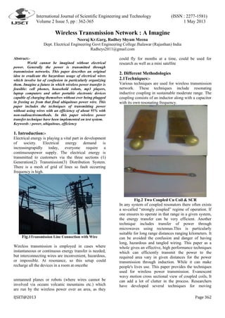
- 1. International Journal of Scientific Engineering and Technology (ISSN : 2277-1581) Volume 2 Issue 5, pp : 362-365 1 May 2013 IJSET@2013 Page 362 Wireless Transmission Network : A Imagine Neeraj Kr.Garg, Radhey Shyam Meena Dept. Electrical Engineering Govt Engineering College Jhalawar (Rajasthan) India Radheys2011@gmail.com Abstract:- World cannot be imagined without electrical power. Generally the power is transmitted through transmission networks. This paper describes an original idea to eradicate the hazardous usage of electrical wires which involve lot of confusion in particularly organizing them. Imagine a future in which wireless power transfer is feasible: cell phones, household robots, mp3 players, laptop computers and other portable electronic devices capable of charging themselves without ever being plugged in freeing us from that final ubiquitous power wire. This paper includes the techniques of transmitting power without using wires with an efficiency of about 95% with non-radioactivemethods. In this paper wireless power transfer technique have been implemented on test system. Keywords : power, ubiquitous, efficiency 1. Introduction:- Electrical energy is playing a vital part in development of society. Electrical energy demand is increasingrapidly today, everyone require a continuouspower supply. The electrical energy is transmitted to customers via the three sections (1) Generation(2) Transmission(3) Distribution System. There is a mesh of grid of lines so fault occurring frequency is high. Fig.1Transmission Line Connection with Wire Wireless transmission is employed in cases where instantaneous or continuous energy transfer is needed, but interconnecting wires are inconvenient, hazardous, or impossible. At resonance, so this setup could recharge all the devices in a room at oncethe unmanned planes or robots (where wires cannot be involved via oceans volcanic mountains etc.) which are run by the wireless power over an area, as they could fly for months at a time, could be used for research as well as a mini satellite 2. Different Methodologies 2.1Techniques:- Various techniques are used for wireless transmission network. These techniques include resonating inductive coupling in sustainable moderate range. The coupling consists of an inductor along with a capacitor with its own resonating frequency. Fig.2 Two Coupled Cu Coil & SCR In any system of coupled resonators there often exists a so-called “strongly coupled” regime of operation. If one ensures to operate in that range in a given system, the energy transfer can be very efficient. Another technique includes transfer of power through microwaves using rectennas.This is particularly suitable for long range distances ranging kilometers. It can be avoided the confusion and danger of having long, hazardous and tangled wiring. This paper as a whole gives an effective, high performance techniques which can efficiently transmit the power to the required area vary in given distances for the power transmission through induction. While it can make people's lives use. This paper provides the techniques used for wireless power transmission. Evanescent wavy motion cross sectional view of coupled coils. It can add a lot of clutter in the process. Researchers have developed several techniques for moving
- 2. International Journal of Scientific Engineering and Technology (ISSN : 2277-1581) Volume 2 Issue 5, pp : 362-365 1 May 2013 IJSET@2013 Page 363 electricity over long distances without wires. Some exist only as theories or prototypes. These techniques are briefly classified into three depending on the distance between the transmitter and receiver. These are: Short, Moderate and Long range. 2.2 Short Distance Induction:- In this method power transfer can take place up to centimeters (15-20cm). Fig.3 Short Distance Induction The action of an electrical transformer is the simplest instance of wireless energy transfer. The primary and secondary circuits of a transformer are electrically isolated from each other. The transfer of energy takes place by electromagnetic coupling through a process known as mutual induction. (An added benefit is the capability to step the primary voltage either up or down.) The electric toothbrush charger is an example of how this principle can be used. A toothbrush's daily exposure to water makes a traditional plug-in charger potentially harmful dangerous. Because of this, most toothbrushes recharge through inductive coupling. For example, the Splash power recharging mat and Edison Electric's Power desk both use coils to create a magnetic field. Electronic devices use corresponding built-in or plug-in receivers to recharge while resting on the mat. 2.3 Moderate Distance Induction: It can be used transfer power between the coils speared by a few meters (3-4m). A splash power mat uses induction to recharge multiple devices simultaneously. Household devices produce relatively small magnetic fields. For this reason, chargers hold devices at the distance necessary to induce a current, which can only happen if the coils are close together. A larger, stronger field could induce current from further away, but the process would be extremely inefficient. Since a magnetic field spreads in all directions, making a larger one would waste a lot of energy. An efficient way to transfer power between coils separated by a few meters is that it can be extended the distance between the coils by adding resonance to the equation. A good way to understand resonance is to think of it in terms of sound. An object's physical structure -- like the size and shape of a trumpet -- determines the frequency at which it naturally vibrates. This is its resonant frequency. It's easy to get objects to vibrate at their resonant frequency and difficult to get them to vibrate at other frequencies. This is why playing a trumpet can cause a nearby trumpet to begin to vibrate. Both trumpets have the same resonant frequency, Induction can take place a little differently if the electromagnetic fields around the coils resonate at the same frequency. The theory uses a curved coil of wire as an inductor. A capacitance plate, which can hold a charge, attaches to each end of the coil. As electricity travels through this coil, the coil begins to resonate. Its resonant frequency is a product of the inductance of the coil and the capacitance of the platesAccording to the theory, one coil can recharge any device that is in range; "Resonant inductive coupling" has key implications in solving the two main problems associated with non-resonant inductive coupling and electromagnetic radiation, one of which is caused by the other; distance and efficiency. Fig.4 Moderate Distance Wireless Electromagnetic induction works on the principle of a primary coil generating a predominantly magnetic field and a secondary coil being within that field so a current is induced within its coils. This causes the relatively short range due to the amount of power required to produce an electromagnetic field. Over greater distances the non-resonant induction method is inefficient and wastes resonate at the same frequency. Much of the transmitted energy just to increase range. This is where the resonance comes in and helps efficiency dramatically by "tunneling" the magnetic field to a receiver coil that Unlike the multiple-layer secondary of a non-resonant transformer, such receiving coils are single layer solenoids with closely spaced capacitor plates on each end, which in combination allow the coil to be tuned to the transmitter frequency thereby eliminating the wide energy wasting "wave problem" and allowing the energy used to focus in on a specific frequency increasing the range..In a short theoretical analysis
- 3. International Journal of Scientific Engineering and Technology (ISSN : 2277-1581) Volume 2 Issue 5, pp : 362-365 1 May 2013 IJSET@2013 Page 364 they demonstrate that by sending electromagnetic waves around in a highly angular waveguide, evanescent waves are produced which carry no energy. Fig.5 Receiving Coil Fig.6 Receiving Circuit An evanescent wave is near field standing wave exhibiting exponential decay with distance. If a proper resonant waveguide is brought near the transmitter, the evanescent waves can allow the energy to tunnel (specifically evanescent wave coupling, the electromagnetic equivalent of tunneling to the power drawing waveguide, where they can be rectified into DC power. Since the electromagnetic waves would tunnel, they would not propagate through the air to be absorbed or dissipated, and would not disrupt electronic devices. As long as both coils are out of range of one another, nothing will happen, since the fields around the coils aren't strong enough to affect much around them. Similarly, if the two coils resonate at different frequencies, nothing will happen. But if two resonating coils with the same frequency get within a few meters of each other, streams of energy move from the transmitting coil to the receiving coil. According to the theory, one coil can even send electricity to several receiving coils, as long as they all resonate at the same frequency. The researchers have named this non-radioactive energy transfersince it involves stationary fields around the coils rather than fields that spread in all directions 2.4Long-Distance Induction:- This method can be used to transfer electrical power in range of kilometers. Whether or not it incorporates resonance, induction generally sends power over relatively short distances. But some plans for wireless power involve moving electricity over a span of miles. A few proposals even involve sending power to the Earth from space. A large, disc-shaped rectifying antenna, or retina, just behind the plane's wings changed the microwave energy from the transmitter into direct-current (DC) electricity. Because of the microwaves' interaction with the rectenna, the system had a constant power supply as long as it was in range of a functioning microwave array. Rectifying antennais central to many wireless power transmission theories. They are usually made an array of dipole antenna, which have positive and negative poles. These antennas connect to shottkey diodes. Here's what happens: 1. Microwaves, which are part of the electromagnetic spectrum, reach the dipole antenna. 2. The antennacollects the microwave energy and transmits it to the diodes. 3. The diodes act like switches that are open or closed as well as turnstiles that let electrons flow in only one direction. They direct the electrons to the rectenna's circuitry. Due to the relatively low cost and high efficiency of power line transmission, wireless power transmission is only practical under two general circumstances: 1) In order to transport necessary power over an impossible or impractical barrier for wires or 2) Rapid development of assets for disaster recovery or military operations that could be aided by wireless power transmission more than by local generators. For that reason most research is focused on applications that solve one of these two problems. 3. TestSystem:- It consists of using a transmission and receiving coils as the coupling antennas. Although the coils do not have to be solenoid they must be in the form of closed loops to both transmit and receive power. To transmit power an alternating current must be passed through a closed loop coil. The alternating current will create a time varying magnetic field at 125KHz/6V/1.6A. The flux generated by the time varying magnetic field will then induce a voltage on a receiving coil closed loop system (Up to 3V, 100mA). This seemingly simple system outlines the major principle that our research investigated. The primary benefits to using inductive coupling are the simplicity of the transmission and receiving antennas, additionally for small power transmission this is a much safer means of conveyance. In this system a receiving circuit to maximize the amount of received power and light an LED at a
- 4. International Journal of Scientific Engineering and Technology (ISSN : 2277-1581) Volume 2 Issue 5, pp : 362-365 1 May 2013 IJSET@2013 Page 365 distance up to two feet. The test system has shown the result of wireless power transfer up to 6cm and 15cm. Fig.7 Test System It was able to create both transmission and receiving circuits capable of transmitting the necessary power to light an LED in a pulsed mode. On average with transmitting one watt of power the receiving circuit was able to receive 100 micro-watts of power. 4. Efficiency:- The efficiency for a wireless power transmission system is determined by the product of the efficiency of all the systems subsystems. It is the ratio between power that reaches the receiver and the power supplied to the transmitter. In Researchsuccessfully demonstrated the ability to power a 60 watt light bulb from a power source that was sevenfeet (2 meters) away using resonating coils. This kind of setup could power or recharge all the devices in one room. Some modifications would be necessary to send power over long distances, like the length of a building or a city. A rectenna may be used to convert the microwave energy back into electricity. Rectenna conversion efficiencies exceeding 95%. Conclusion:- In this paper power transfer using wireless technique have been discussed. Moderate distance induction technique is presently in use. In this technique concept of inductive coupling and resonant in both part of system was used. Emerging technology can be useful for long transmission system. It will improve the efficiency as well as reliability of transmission system, it also reduce the cost of the system. In the long run, this can reduce our society’s dependency on batteries. The test system have shown the practically feasibility of the system and shown the concept of wireless power transfer up to 6cm & 15cm.wwhich increase the efficiency of system and reducing the cost. References:- I. Vinoth Kumar, ‖ Wireless Energy Transfer Possibility‖ http://thinkquestprojects.blogspot.in/2012/01/wireless-energy- transfer-possibility.html II. Thomas W., "Wireless Transmission of Power now Possible”. III. U.S. Patent 787,412, "Art of Transmitting Electrical Energy through the Natural Mediums". IV. Dombi J., (1982): Basic concepts for a theory of evaluation: The aggregative operator. European Jr. Operation Research 10, 282-293. V. Tesla, N., “The transmission of electric energy without wires”, Electrical World, March 5, 1904. VI. Brown, W. C., “Beamed microwave power transmission and its application to space”, IEEE Trans. Microwave Theory Tech., vol. 40, no. 6, 1992, pp.1239-1250. VII. Kaya, N., S. Ida, Y. Fuji no, and M. Fujita, “Transmitting antenna system for airship demonstration of Space Energy and Transportation” IEEE Vol.1, No.4, 1996, pp.237-245. VIII. Fujiwara, E., Y. Takahashi, N. Tanaka, K. Saga, “Compact Microwave Energy Transmitter (COMET)”, Proc. of Japan-US Joint Workshop on SSPS (JUSPS), 2003, pp.183-185. IX. www.howstuffworks.com (How Micro Ovens Work – A Cooking Oven for the 21st century. By Gabriel Gache) [7] "Goodbye wires…” MIT News. 2007-06-07. X. http://web.mit.edu/newsoffice/2007/wireless-0607.html. XI. http://en.wikipedia.org/wiki/wireless.