Instructions SCHMIDT & BENDER MTC-LT | Optics Trade
•
0 likes•25,594 views

Instructions SCHMIDT & BENDER MTC-LT | Optics Trade

Recommended
Recommended
More Related Content
More from Optics-Trade
More from Optics-Trade (20)
Recently uploaded
Recently uploaded (20)
Instructions SCHMIDT & BENDER MTC-LT | Optics Trade
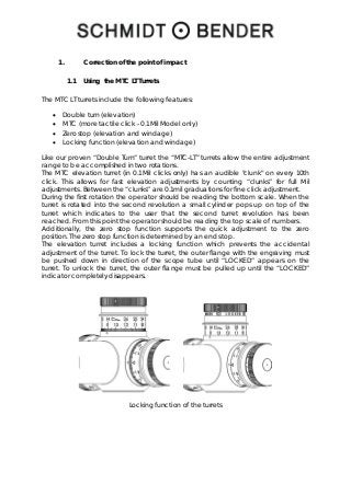
- 1. 1. Correction of the point of impact 1.1 Using the MTC LT Turrets The MTC LT turrets include the following features: • Double turn (elevation) • MTC (more tactile click - 0.1Mil Model only) • Zero stop (elevation and windage) • Locking function (elevation and windage) Like our proven “Double Turn” turret the “MTC-LT” turrets allow the entire adjustment range to be accomplished in two rotations. The MTC elevation turret (in 0.1Mil clicks only) has an audible "clunk" on every 10th click. This allows for fast elevation adjustments by counting “clunks” for full Mil adjustments. Between the “clunks” are 0.1mil graduations for fine click adjustment. During the first rotation the operator should be reading the bottom scale. When the turret is rotated into the second revolution a small cylinder pops up on top of the turret which indicates to the user that the second turret revolution has been reached. From this point the operator should be reading the top scale of numbers. Additionally, the zero stop function supports the quick adjustment to the zero position. The zero stop function is determined by an end stop. The elevation turret includes a locking function which prevents the accidental adjustment of the turret. To lock the turret, the outer flange with the engraving must be pushed down in direction of the scope tube until “LOCKED” appears on the turret. To unlock the turret, the outer flange must be pulled up until the “LOCKED” indicator completely disappears. Locking function of the turrets
- 2. 1.2 Preliminary adjusting and fine adjusting when sighting in When sighting in the scope for the first time a test shooting for zeroing the scope must be performed. Therefore, make sure that the parallax is set to the correct distance and that elevation is set to “13”and windage is set to “0”. The centering of the shot pattern is then performed according to paragraph 1.3 and 1.4. Now, lock both turrets, elevation and windage, then unlock the two Allen head screws in the outside diameter in line with the “LOCKED” signage using an Allen key Now unlock the turrets by pulling up the outer flange with the engraving and turn both turrets until the engraved “0” is indicated by the triangle on the saddle. Now, lock the turrets by pushing down the outer flange with the engraving and tighten the two Allen head screws with an Allen key. The turret caps are secured by an additional screw and cannot be removed. The clicks of the turrets can be felt and heard when the screws are unlocked. This has no impact on the process of zeroing as the thread piece does not move while the setscrews are loose.
- 3. Zeroing of the scope – unscrewing the Allen head screws 1.3 Elevation adjustment The point of impact is moved by 0,1 Mrad on 100m with every click. A too low point of impact is corrected by rotating the elevation turret counter-clockwise, a too high point of impact by rotating the elevation turret clockwise. Elevation adjustment 1.4 Windage adjustment The point of impact is moved by 0.1 Mrad on 100m with every click. A too far left point of impact is corrected by rotating the windage turret counter-clockwise, a too far right point of impact is corrected by rotating the turret clockwise Windage adjustment