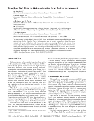
Growth of GaN films on GaAs substrates in an As-free environment
•
0 gefällt mir•406 views

J. Vac. Sci. Technol. B 24/3, May/Jun 2006

Empfohlen
Empfohlen
Weitere ähnliche Inhalte
Was ist angesagt?
Was ist angesagt? (12)
Andere mochten auch
Ähnlich wie Growth of GaN films on GaAs substrates in an As-free environment
Ähnlich wie Growth of GaN films on GaAs substrates in an As-free environment (20)
Mehr von Oleg Maksimov
Mehr von Oleg Maksimov (20)
Kürzlich hochgeladen
Kürzlich hochgeladen (20)
Growth of GaN films on GaAs substrates in an As-free environment
- 1. Growth of GaN films on GaAs substrates in an As-free environment O. Maksimova͒ Electro-Optics Center, Pennsylvania State University, Freeport, Pennsylvania 16229 P. Fisher and H. Du Department of Materials Science and Engineering, Carnegie Mellon University, Pittsburgh, Pennsylvania 15213 J. D. Acord and X. Weng Department of Materials Science and Engineering, Pennsylvania State University, University Park, Pennsylvania 16802 M. Skowronski Electro-Optics Center, Pennsylvania State University, Freeport, Pennsylvania 16229 and Department of Materials Science and Engineering, Carnegie Mellon University, Pittsburgh, Pennsylvania 15213 V. D. Heydemann Electro-Optics Center, Pennsylvania State University, Freeport, Pennsylvania 16229 ͑Received 14 September 2005; accepted 5 December 2005; published 31 May 2006͒ We investigated growth of GaN films on ͓001͔ GaAs substrates by plasma-assisted molecular beam epitaxy in an As-free chamber. The crystalline quality and the surface morphology of the films were studied with x-ray diffraction and transmission electron, scanning electron, and atomic force microscopes. We determined that direct GaN deposition on the thermally desorbed substrate resulted in the growth of a polycrystalline film containing misoriented grains and inclusions. We achieved a significant improvement of the film quality by adopting a procedure consisting of a substrate nitridation, deposition of a low-temperature buffer layer, and a high-temperature overgrowth. © 2006 American Vacuum Society. ͓DOI: 10.1116/1.2192538͔ I. INTRODUCTION GaAs leads to the growth of a polycrystalline ␣-GaN film. Although the GaN c axis is preferentially oriented perpen- GaN materials are technologically important for a variety dicular to the surface, the film contains misoriented hexago- of device application.1,2 They are ideal candidates for fabri- nal domains and cubic inclusions. We achieve a significant cation of high power microwave devices, high frequency improvement of the crystallinity and effectively suppress field effect transistors, high electron mobility transistors, misoriented domains by adopting the growth procedure that light emitters, and detectors operating in the visible to UV consists of a substrate nitridation, deposition of a low- spectral range. High quality hexagonal GaN ͑␣-GaN͒ films temperature buffer layer, and a high-temperature overgrowth. and heterostructures are usually grown either by metal or- ganic chemical vapor deposition ͑MOCVD͒ or by molecular beam epitaxy ͑MBE͒ on sapphire ͑␣-Al2O3͒ and 6H-SiC II. EXPERIMENTAL DETAILS substrates.3,4 Growth on ͓001͔ GaAs is much less studied, The samples are fabricated in a custom-built MBE system although these substrates provide several advantages, such designed for nitride growth. It is equipped with a Ga effusion as, low cost, easy cleavage along ͓011͔ direction, closer ther- cell, a radio frequency excited nitrogen plasma source, a mal expansion coefficient matching, and possibility to grow retractable ion gauge for flux calibration, and a differentially cubic -GaN. pumped electron gun. Differential pumping allows reflection When GaN is grown on GaAs, an optimization of the high-energy electron diffraction ͑RHEED͒ measurements GaAs surface, by growing a GaAs buffer layer, always pre- during the GaN growth, when the pressure reaches 5 cedes GaN deposition.5–7 Also, -GaN is usually stabilized ϫ 10−5 Torr. The RHEED patterns are recorded by a digital with an impinging As flux, while as flux termination pro- camera and processed on a computer. motes formation of a mixed polycrystalline phase.8 However, The growth is performed on semi-insulating epiready As gets incorporated into the GaN alloy, degrading lumines- ͓001͔ GaAs substrates indium mounted to molybdenum cent and transport properties of the film.9,10 Therefore, it is of blocks. Prior to introduction to the growth chamber, the sub- interest to explore GaN growth in the As-free environment. strates are outgassed at 300 ° C for 1 h in a transfer chamber. In this article we report on the growth of GaN films on the The surface oxide layer is desorbed at 500 ° C in the absence ͓001͔ GaAs substrates in an As-free MBE chamber. We ob- of As by pulsed Ga deposition.11 Specular RHEED intensity serve that direct GaN deposition on the thermally desorbed is monitored during the oxide desorption to prevent over supply of Ga. a͒ Author to whom correspondence should be addressed; electronic mail: The GaN is grown at a rate of ϳ500 nm/ h and the films maksimov@netzero.net are 1.5– 3.5 m thick. The growth front is monitored in situ 1671 J. Vac. Sci. Technol. B 24„3…, May/Jun 2006 1071-1023/2006/24„3…/1671/5/$23.00 ©2006 American Vacuum Society 1671
- 2. 1672 Maksimov et al.: Growth of GaN films on GaAs substrates 1672 FIG. 2. XRD -2 scans of ϳ1.5 m thick GaN films grown on GaAs ͑A͒ by direct deposition, ͑B͒ after nitridation, and ͑C͒ after nitridation on the low-temperature buffer layer. FIG. 1. RHEED patterns for ͑A͒ GaAs substrate after oxide desorption, ͑B͒ However, ␣-GaN misoriented grains ͑͗1011͘, ͗1012͘, ͗1120͘, GaN film grown by direct deposition, ͑C͒ nitridated GaAs, ͑D͒ annealed ͗1013͒͘ and -GaN inclusions ͑͗002͒͘ are also present. The nitridated GaAs, ͑E͒ GaN film grown at 600 ° C after nitridation, and ͑F͒ GaN film grown at 750 ° C after nitridation on the low-temperature buffer surface of the film is very rough and exhibits a grain struc- layer. ture, as shown in Figs. 3͑a͒ and 3͑b͒. Cross-sectional SEM image ͑Fig. 4͒ reveals that GaN grows in columnar crystals, in agreement with other attempts to deposit GaN without by RHEED. The substrate temperature is measured by a ther- stabilizing As flux.12 mocouple in contact with the backside of the mounting It is suggested that low-temperature “nitridation” ͑the wa- block. The wafer is rotated during the deposition for the fer is exposed to nitrogen plasma͒ followed by high- growth uniformity. temperature annealing can produce a smooth single-crystal The crystalline quality is studied ex situ by x-ray diffrac- GaN layer.13 This layer can be used as a template for further tion ͑XRD͒, scanning electron microscopy ͑SEM͒, and trans- GaN growth. To adopt this strategy we nitridate GaAs for mission electron microscopy ͑TEM͒. For TEM studies, 15 min at 400 ° C and anneal it for half an hour at 600 ° C. cross-sectional specimens are prepared using conventional Surface reconstruction disappears during the first few min- mechanical thinning followed by argon-ion milling. TEM, utes of GaAs wafer exposure to nitrogen plasma, suggesting high-resolution TEM, and selected area diffraction ͑SAD͒ formation of an amorphous GaAsN layer at the surface. We are carried out in a JEOL 2010F transmission electron mi- observe an arc pattern after approximately 5 min, indicating croscope operating at 200 keV. The surface morphology of development of a preferred orientation in a disordered layer. the films is examined by atomic force microscopy ͑AFM͒ Spotlike features with hexagonal symmetry develop by the with scanned areas up to 10ϫ 10 m2. end of nitridation ͓Fig. 1͑c͔͒. Annealing at 600 ° C sharpens diffraction spots ͓Fig. 1͑d͔͒, demonstrating recrystallization of GaN phase. The diffraction spots are relatively broad, sig- III. RESULTS AND DISCUSSION nifying that a very defective GaN layer forms at the begin- Oxide desorption typically results in a slightly distorted ning. However, they become significantly sharper and elon- GaAs surface and the RHEED pattern is characterized by gated during the MBE growth ͓Fig. 1͑e͔͒, indicating that the modulated intensity, twofold reconstruction along the ͓011͔ final GaN film has a better crystalline quality and a smoother direction, and, occasionally, faceting along the ͓0-11͔ direc- surface. An XRD -2 scan of a film grown on the nitridated tion. Kikuchi lines are clearly evident, indicating that GaAs substrate is shown in Fig. 2͑b͒. The main diffraction peak is surface is free of oxide layer ͓Fig. 1͑a͔͒. ͗0002͘ ␣-GaN. A very weak ͗002͘ -GaN diffraction is also When we deposit GaN directly on such a surface, we present. It may be attributed to cubic grains at the observe an arc RHEED pattern, characteristic for the poly- GaN / GaAs interface that can develop during the nitridation- crystalline growth ͓Fig. 1͑b͔͒. An XRD -2 scan of a film annealing process. AFM images ͓Figs. 3͑c͒ and 3͑d͔͒ show grown at 600 ° C is shown in Fig. 2͑a͒. It reveals that the film that GaN surface is much smoother and the grains coalesce is a highly textured ␣-GaN with ͗0001͘ preferred orientation. better. Cross-sectional SEM images, not shown, also demon- J. Vac. Sci. Technol. B, Vol. 24, No. 3, May/Jun 2006
- 3. 1673 Maksimov et al.: Growth of GaN films on GaAs substrates 1673 FIG. 3. AFM images of ϳ1.5 m thick GaN films grown on GaAs ͓͑A͒ and ͑B͔͒ by direct deposition, ͓͑C͒ and ͑D͔͒ after nitridation, and ͓͑E͒ and ͑F͔͒ after nitridation on the low-temperature buffer layer. strate that the film is denser, the GaN columns are more thick interfacial GaN layer at 600 ° C after nitridation. Next, uniform, and the boundaries between them are less evident. we raise the wafer temperature to 750 ° C for consequent It is reported that significant improvement of the quality GaN growth. When the growth is initiated, we observe a of the GaN films on ͓001͔ Si substrates can be achieved by a streaky ͑1 ϫ 1͒ RHEED pattern ͓Fig. 1͑f͔͒. An XRD -2 two-step growth process. A thin buffer layer is grown at a scan of this film is shown in Fig. 2͑c͒. The spectrum, similar relatively low temperature; the rest of the film is grown at a to the previous, is dominated by ͗0002͘ ␣-GaN diffraction. higher temperature.14,15 This procedure is successfully ap- However, the intensity ratio of ͗0002͘ ␣-GaN / ͗002͘ GaAs plied to other substrates including ␣-Al2O3, 6H-SiC, and ZnO.16,17 To investigate this approach, we deposit a 50 nm peaks, that can serve as an estimate of the crystallinity, in- JVST B - Microelectronics and Nanometer Structures
- 4. 1674 Maksimov et al.: Growth of GaN films on GaAs substrates 1674 axis bright-field image. Similar to previous films, GaN dis- plays columnar structure. The columns are separated by straight boundaries and have well-defined surface facets. We present a high-resolution TEM image of two neighboring columns in Fig. 5͑d͒. The image, collected close to the film surface along the ͓11-20͔ GaN zone axis, indicates that grain boundaries consist of an amorphous GaN. Figure 6 shows SAD pattern collected from the top part of the film along the ͓11-20͔ zone axis. It displays both a bright wurtzite pattern and an additional set of weak spots, most probably, originat- ing from planar defects or double diffraction. In addition, the two columns have slightly different contrasts, possibly, due to the twist and tilt between them. Figure 5͑b͒ shows a ͓1-100͔ two-beam dark-field image of FIG. 4. Cross-sectional SEM image of an ϳ1.5 m thick GaN film grown GaN film with the top part milled away. It is evident that the by direct deposition on GaAs. film consists of two different regions separated, for clarity, by a dashed line. Unlike the top part, the bottom part of the film is not columnar and contains a higher density of defects. creases from 3 to 20, indicating higher quality of the film. Based on the thickness, ϳ70 nm, we assign it to the low- AFM images ͓Figs. 3͑e͒ and 3͑f͔͒ also show superior surface temperature buffer layer. We suggest that, similar to morphology, in agreement with streaky RHEED pattern ob- MOCVD on Al2O3, low-temperature buffer serves as a served during the growth. nucleation layer for prismatic GaN growth.18 A high- We use TEM for detailed analysis of GaN grown under resolution TEM image of the interface between epilayer and the last conditions. Figure 5͑a͒ shows a large scale on-zone- substrate is presented in Fig. 5͑c͒. The image, collected along FIG. 5. ͑A͒ On-zone-axis bright-field image showing the GaN / GaAs heterostructure. ͑B͒ ͓1-100͔ two-beam dark-field image of GaN / GaAs. The top part of the film is milled away. ͑C͒ HRTEM image collected near the GaN / GaAs interface along the ͓110͔ GaAs zone axis. ͑D͒ HRTEM image collected along the ͓11-20͔ GaN zone axis, showing two neighboring columns. J. Vac. Sci. Technol. B, Vol. 24, No. 3, May/Jun 2006
- 5. 1675 Maksimov et al.: Growth of GaN films on GaAs substrates 1675 talline ␣-GaN containing misoriented domains and cubic in- clusions. The surface is very rough and consists of coalesc- ing grains. We use a three-step process to improve the film quality. The procedure consists of substrate nitridation, depo- sition of a GaN buffer layer at a low temperature, and epi- taxial regrowth at an elevated temperature. These steps sup- press misorientation and improve surface morphology of the film. TEM demonstrates the presence of a 5 nm thick amor- phous layer at the GaAs/ GaN interface. We suggest that it is due to the incomplete recrystallization of GaAsN layer and believe that further improvement of nitridation conditions should resolve this problem. ACKNOWLEDGMENT The work is supported by ONR ͑Dr. C. E. C. Wood͒. 1 S. N. Mohammad, A. A. Salvador, and H. Morkoc, Proc. IEEE 83, 1306 ͑1995͒. 2 R. Fen and J. C. Zolper, Wide Bandgap Electronic Devices ͑World Scientific, Singapore, 2003͒. 3 H. X. Jiang and J. Y. Lin, Opto-Electron. Rev. 10, 271 ͑2002͒. 4 O. Brandt, R. Muralihadharan, A. Thamm, P. Waltereit, and K. H. Ploog, Appl. Surf. Sci. 175, 419 ͑2001͒. 5 O. Brandt, H. Yang, A. Trampert, M. Wassermeier, and K. H. FIG. 6. SAD pattern collected from the top part of the GaN film. Ploog, Appl. Phys. Lett. 71, 473 ͑1997͒. 6 L. W. Sung, H. H. Lin, and C. T. Chia, J. Cryst. Growth 241, 320 ͑2002͒. 7 R. Kimura, T. Suzuki, M. Ouchi, K. Ishida, and K. Takahashi, J. Cryst. the ͓110͔ GaAs zone axis, demonstrates a 5 nm thick amor- Growth 278, 411 ͑2005͒. 8 phouslike layer at the interface. We believe that it forms due T. S. Cheng, L. C. Jenkins, S. E. Hooper, C. T. Foxon, J. W. Orton, and D. E. Lacklison, Appl. Phys. Lett. 66, 1509 ͑1995͒. to the incomplete recrystallization of nitridated GaAs sur- 9 H. Okumura, H. Hamaguci, G. Feuillet, Y. Ishida, and S. Yoshida, Appl. face. An amorphous layer at the interface can facilitate Phys. Lett. 72, 3056 ͑1998͒. 10 growth of misoriented grains, significantly degrading the A. Bell, F. A. Ponce, S. V. Novikov, C. T. Foxon, and I. Harrison, Appl. crystalline quality of the film. At low temperature nitridation Phys. Lett. 79, 3239 ͑2001͒. 11 Z. R. Wasilewski, J. M. Baribeau, M. Beaulieu, X. Wu, and G. I. Sproule, is hindered by kinetic restrictions on the atomic migration J. Vac. Sci. Technol. B 23, 1534 ͑2004͒. and leads to island growth of an amorphous film. At high 12 L. C. Jenkins, T. S. Cheng, C. T. Foxon, S. E. Hooper, J. W. Orton, S. V. temperatures surface etching by nitrogen plasma leads to Novikov, and V. V. Tretyakov, J. Vac. Sci. Technol. B 13, 1585 ͑1995͒. 13 faceting and rough morphology.13 Thus, a careful further ad- I. Aksenov, H. Iwai, Y. Nakada, and H. Okumura, J. Vac. Sci. Technol. B 17, 1525 ͑1999͒. justment of the nitridation conditions ͑substrate temperature, 14 T. Lei, M. Fanciulli, R. J. Molnar, T. D. Moustakas, R. J. Graham, and J. nitridation time, and nitrogen flow͒ is necessary to eliminate Scanlon, Appl. Phys. Lett. 59, 944 ͑1991͒. 15 amorphous layer and form a sharp heterointerface. T. Lei, T. D. Moustakas, R. J. Graham, Y. He, and S. J. Berkowitz, J. Appl. Phys. 71, 4933 ͑1992͒. 16 H. M. Ng, D. Doppalapudi, D. Korakakis, R. Singh, and T. Moustakas, J. IV. CONCLUSION Cryst. Growth 189, 349 ͑1998͒. 17 X. Gu, M. A. Reshchikov, A. Teke, D. Johnstone, H. Morkoc, B. Nemeth, In summary, GaN films are grown on ͓001͔ GaAs sub- and J. Nause, Appl. Phys. Lett. 84, 2268 ͑2004͒. strates by MBE in an As-free chamber. Direct deposition on 18 K. Hiramatsu, S. Itoh, H. Amano, I. Akasaki, N. Kuwano, T. Shiraishi, thermally desorbed GaAs results in the growth of polycrys- and K. Oki, J. Cryst. Growth 115, 628 ͑1991͒. JVST B - Microelectronics and Nanometer Structures