Strategies for Landing an Oracle DBA Job as a Fresher
Lte scfdma wp_0804_agilent
1. WHITEPAPER
De-mystifying Single Carrier FDMA
The New LTE Uplink
Third-generation wireless communication systems based on W-CDMA (wideband code-division
multiple access) are being deployed all over the world. To ensure that these systems remain competi-
tive, the 3GPP (3rd Generation Partnership Project) initiated a project in late 2004 for the long-term
evolution (LTE) of 3GPP cellular technology.
This article focuses on the physical layer (“Layer 1”) characteristics of the LTE uplink, describing the
new Single-Carrier Frequency Division Multiple Access (SC-FDMA) transmission scheme and some
of the measurements associated with it. Understanding the details of this new transmission scheme
and measurements is a vital step towards developing LTE UE designs and getting them to market.
Written by: Moray Rumney BSc, C. Eng, MIET
Lead Technologist, Agilent Technologies
The LTE specifications are being documented in Release 8 of new transmission scheme called SC-FDMA. This new scheme borrows
the 3GPP standard. The core specifications are scheduled to be from both traditional single-carrier schemes as well as from OFDM.
completed by mid-2008 with the conformance test specifications
following approximately six months later. OFDM and OFDMA
With early system deployment expected in the 2010 OFDM has been around since the mid 1960s and is now used in
timeframe, LTE provides a framework for an evolved 3G network, a number of non-cellular wireless systems such as Digital Video
and aims specifically to achieve the following: Broadcast (DVB), Digital Audio Broadcast (DAB), Asymmetric Digital
• Increased uplink peak data rates up to 86.4 Mbps in a 20 MHz Subscriber Line (ADSL) and some of the 802.11 family of Wi-Fi
bandwidth with 64QAM (quadrature amplitude modulation) standards. OFDM’s adoption into mobile wireless has been delayed
• Increased downlink peak data rates up to 172.8 Mbps in a 20 for two main reasons. The first is the sheer processing power which
MHz bandwidth with 64QAM and 2x2 SU-MIMO (single-user is required to perform the necessary FFT operations. However, the
multiple input/multiple output) continuing advance of signal processing technology means that this
• Maximum downlink peak data rates up to 326.4 Mbps using 4x4 is no longer a reason to avoid OFDM, and it now forms the basis
SU-MIMO of the LTE downlink. The other reason OFDM has been avoided in
• Spectrum flexibility with scalable uplink and downlink channel mobile systems is the very high peak to average ratio (PAR) signals
bandwidths from 1.4 MHz up to 20 MHz it creates due to the parallel transmission of many hundreds of
• Improved spectral efficiency, with a 2-4 times improvement over closely-spaced subcarriers. For mobile devices this high PAR is prob-
Release 6 HSPA (high speed packet access) lematic for both power amplifier design and battery consumption,
• Sub-5 ms latency for small IP (internet protocol) packets and it is this concern which led 3GPP to develop the new SC-FDMA
• Mobility optimized for low mobile speed from 0 to 15 km/h; transmission scheme.
higher mobile speeds up to 120 km/h will be supported with Multiple access in the LTE downlink is achieved by using
high performance with the system operating up to 350 km/h an elaboration of pure OFDM called orthogonal frequency division
• Co-existence with legacy systems while evolving towards an all-IP multiple access (OFDMA). This method allows subcarriers to be
network allocated to different users. This facilitates the trunking of many
lower-rate users as well as enabling the use of frequency hopping to
The LTE Air Interface mitigate the effects of narrowband fading.
There are two primary duplexing modes used in LTE which are
frequency division duplex (FDD) and time division duplex (TDD). SC-FDMA
Variants including half-rate FDD are also anticipated. The integration SC-FDMA is a hybrid transmission scheme which combines the low
of the FDD and TDD modes of LTE is much closer than was the case PAR characteristics of single-carrier transmission systems - such as
with UMTS. The downlink transmission scheme is based on orthogo- those used for GSM and CDMA - with the long symbol time and
nal frequency division multiplexing (OFDM) and the uplink uses a flexible frequency allocation of OFDM. The principles behind SC-
2. sequentially. Since this example involves four
subcarriers, four data symbols are transmitted
sequentially in one SC-FDMA symbol period.
The SC-FDMA symbol period is the same length
as the OFDMA symbol at 66.7µs but due to
sequential transmission, the data symbols are
shorter being 66.7/M µs. A consequence
of the higher data rate symbols means more
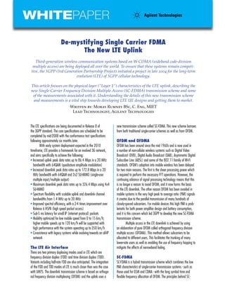
Figure 1 SC-FDMA signal generation
bandwidth is required, so each data symbol occupies 60 kHz of
FDMA signal generation are shown in Figure 1. This is taken from spectrum rather than the 15 kHz for the slower data symbols used
Figure 1 of the study phase report for the LTE physical layer 3GPP for OFDMA. After the four data symbols have been transmitted, the
TR 25.814. CP is inserted.
Following this graphical comparison of OFDMA and SC-FDMA,
On the left hand side of Figure 1 the data symbols are depicted the detail of the SC-FDMA signal generation process is shown in
in the time domain. The symbols are converted to the frequency Figures 3 and 4. A time domain representation of the data symbol
domain using an FFT, and then in the frequency domain they are sequence is first generated as shown in Figure 3.
mapped to the desired location in the overall carrier bandwidth.
They must then be converted back to the time domain in order to
have the cyclic prefix inserted prior to transmission. An alternative
name for SC-FDMA is Discrete Fourier Transform Spread OFDM
(DFT-SOFDM).
An alternative description is provided in Figure 2 which
shows, in frequency and time, how OFDMA and SC-FDMA would
each transmit a sequence of 8 QPSK data symbols. For this Figure 3 Creating the time-domain waveform of an
simplified example, the number of subcarriers (M) is set to four. SC-FDMA symbol
For OFDMA, four (M) symbols are taken in parallel, each of them
modulating its own subcarrier at the appropriate QPSK phase. Each For this four subcarrier example a sequence of four data
data symbol occupies 15 kHz for the period of one OFDMA symbol
symbols is required to generate one SC-FDMA symbol. Using the
which lasts for 66.7µs. At the start of the next OFDMA symbol, the
first four of the color-coded QPSK data symbols from Figure 2, the
guard interval containing the cyclic prefix (CP) is inserted. The CP is
process creates one SC-FDMA symbol in the time domain by com-
a copy of the end of a symbol prepended to the start of the symbol.
puting the trajectory traced by moving from one QPSK data symbol
Due to the parallel transmission, the data symbols are the same
to the next. This is done at M times the rate of the SC-FDMA
length as the OFDMA symbols. symbol such that one SC-FDMA symbol contains M consecutive
In the SC-FDMA case, the data symbols are transmitted
QPSK data symbols. For simplicity, we will not discuss time-domain
filtering of the data symbol
transitions even though such
filtering will be present in any
real implementation.
Having created an IQ
representation in the time do-
main of one SC-FDMA symbol,
the next stage is to represent
this in the frequency domain us-
ing a discrete Fourier transform
(DFT; Figure 4).
The DFT sampling fre-
quency is chosen such that the
time-domain waveform of one
SC-FDMA symbol is fully repre-
sented by M DFT bins spaced
15 kHz apart, where each bin
represents one subcarrier with
Figure 2 Comparison of OFDMA and SC-FDMA transmitting a series of QPSK data symbols amplitude and phase held
3. even SC-FDMA with its short data symbols benefits from multipath
protection. Figure 2 shows the SC-FDMA subcarriers all at the same
amplitude but in reality each will have its own amplitude and phase
for any one SC-FDMA symbol period.
To conclude SC-FDMA signal generation, the process follows
the same steps as for OFDMA. Performing an inverse FFT converts
the frequency-shifted signal to the time domain and inserting the CP
Figure 4. Baseband and shifted frequency domain provides OFDMA’s fundamental robustness against multipath.
representations of an SC-FDMA symbol Figure 5 shows the close relationship between SC-FDMA and
OFDMA. The orange blocks represent OFDMA processing and the
constant for the 66.7µs SC-FDMA symbol period. There is always a blue blocks represent the additional time domain processing required
one-to-one correlation between the number of data symbols to be for SC-FDMA.
transmitted during one SC-FDMA symbol period and the number of
DFT bins created — which in turn becomes the number of occupied
subcarriers. When an increasing number of data symbols are UL Signals Full Name Purpose
transmitted during one SC-FDMA period, the time-domain waveform DMRS (Demodulation) Used by the base station
changes faster, generating a higher bandwidth and hence requiring Reference Signal for synchronization to the
more DFT bins to fully represent the signal in the frequency domain. UE and for UL channel
estimation.
Multipath Resistance With Short Data Associated with PUCCH or
Symbols? PUSCH
At this point it is reasonable to ask, “How can SC-FDMA still be resis- SRS Sounding Reference Used for channel estima-
tant to multipath when the data symbols are still short?” In OFDMA, Signal tion when there is no
the modulating data symbols are constant over the 66.7 µs OFDMA PUCCH or PUSCH
symbol period but an SC-FDMA symbol is not constant over time UL Channels Full name Purpose
since it contains M data symbols of much shorter duration. The
multipath resistance of the OFDMA demodulation process seems to PRACH Physical Randon Call setup
rely on the long data symbols that map directly onto the subcarriers. Access Channel
Fortunately, it is the constant nature of each subcarrier— not the PUCCH Physical Uplink Scheduling, ACK/NACK
data symbols — that provides the resistance to delay spread. As Control Channel
shown earlier, the DFT of the time-varying SC-FDMA symbol gener- PUSCH Physical Uplink Payload
ated a set of DFT bins constant in time during the SC-FDMA symbol Shared Channel
period even though the modulating data symbols varied over the
Table 1 Uplink signals and channels
same period. It is inherent to the DFT process that the time-varying
SC-FDMA symbol - made of M serial data symbols - is represented
in the frequency domain by M time-invariant subcarriers. Thus,
Figure 5 Simplified model of SC-FDMA generation and reception
4. The key point to note is that the signal which is Physical Layer Structure
converted from the frequency domain back to the time domain The LTE physical layer comprises two types of signals known as
is no more than a frequency shifted version of a series of QPSK physical signals and physical channels. Physical signals are gener-
symbols. This example illustrates the main reason SC-FDMA was ated in Layer 1 and used for system synchronization, cell identifica-
developed: that is, the PAR of the final signal is no worse than tion, and radio channel estimation. Physical channels carry data
that of the original data symbols, which in this case was QPSK. from higher layers including control, scheduling, and user payload.
This is very different to OFDMA where the parallel transmission Table 1 shows the uplink physical signals and channels.
of the same QPSK data symbols creates statistical peaks - much
like Gaussian noise - far in excess of the PAR of the data symbols Uplink Frame Structure
themselves. Limiting PAR using SC-FDMA significantly reduces There are two uplink frame structures, one for FDD operation
the need for the mobile device to handle high peak power. This called type 1 and the other for FDD operation called type 2. Frame
lowers costs and reduces battery drain. structure type 1 is 10 ms long and consists of ten subframes, each
Figure 6 Frame Structure 1 for uplink showing mapping for DMRS and PUSCH
Figure 7 Frame
Structure 1 for the
uplink showing
one subframe vs.
frequency
5. Figure 8 Analysis of a 16QAM SC-FDMA signal
comprising two 0.5 ms slots. Figure 6 shows how the DMRS and Analyzer software. The IQ constellation in trace A (top left) shows
PUSCH map onto the frame structure. The number of symbols in that this is a 16QAM signal. The unity circle represents the DMRS
a slot depends on the CP length. For a normal CP, there are seven occurring every seventh symbol, which are phase-modulated
SC-FDMA symbols per slot. For an extended CP used for when the using an orthogonal Zadoff-Chu sequence.
delay spread is large, there are six SC-FDMA symbols per slot. Trace B (lower left) shows signal power versus frequency.
Demodulation reference signals are transmitted in the The frequency scale is in 15 kHz sub-carriers numbered from
fourth symbol (that is, symbol number 3) of every slot. The -600 to 599, which represents a bandwidth of 18 MHz or 100
PUSCH can be transmitted in any other symbol. RB. The nominal channel bandwidth is therefore 20 MHz and
Figure 7 shows the uplink frame structure type 1 in both the allocated signal bandwidth is 5 MHz towards the lower end.
frequency and time. Each vertical bar represents one subcarrier. The brown dots represent the instantaneous subcarrier amplitude
Transmissions are allocated in units called resource blocks (RB) and the white dots the average over 10 ms. In the center of the
comprising 12 adjacent subcarriers for a period of 0.5 ms. In trace, the spike represents the local oscillator (LO) leakage - IQ
addition to the DMRS and PUSCH the figure also shows the offset - of the signal; the large image to the right is an OFDM
PUCCH which is always allocated to the edge RB of the channel artifact deliberately created using 0.5 dB IQ gain imbalance in
bandwidth alternating from low to high frequency on adjacent the signal. Both the LO leakage and the power in non-allocated
slots. Note that the frequency allocation for one UE is typically sub-carriers will be limited by the 3GPP specifications.
less than the system bandwidth. This is because the number of Trace C (top middle) shows a summary of the measured
RB allocated directly scales to the transmitted data rate which impairments including the error vector magnitude (EVM),
may not always be the maximum. The DMRS is only transmitted frequency error, and IQ offset. Note the data EVM at 1.15 percent
within the PUSCH and PUCCH frequency allocation-unlike the is much higher than the DMRS EVM at 0.114 percent. This is
reference signals on the downlink which are always transmitted due to a +0.1 dB boost in the data power as reported in trace
across the entire channel bandwidth even if the channel is not E, which for this example was ignored by the receiver to create
fully occupied. data-specific EVM. Also note the DMRS power boost is reported
If the base station needs to estimate the uplink channel as +1 dB, which can also be observed in the IQ constellation
conditions when no control or payload data is scheduled then because the unity circle does not pass through eight of the 16QAM
it will allocate the SRS which is independent of the PUSCH and points. Trace D (lower middle) shows the distribution of EVM by
PUCCH. The PUSCH can be modulated at QPSK, 16QAM or subcarrier. The average and peak of the allocated signal EVM is in
64QAM. The PUCCH is only QPSK and the DMRS is BPSK with a line with the numbers in trace C. The EVM for the non-allocated
45 degree rotation. subcarriers reads much higher, although this impairment will be
specified with a new “in-band emission” requirement as a power
Analyzing an SC-FDMA Signal ratio between the allocated RB and unallocated RB. The ratio for
Figure 8 shows some of the measurements that can be made on this particular signal is around 30 dB as trace B shows. The blue
a typical SC-FDMA signal using the Agilent 89601A Vector Signal dots in trace D also show the EVM of the DMRS, which is very low.
6. Figure 9 Agilent’s MXG Vector Signal Generator with LTE Signal Studio software and the MXA Signal Analyzer with
89600 LTE VSA software provides the most comprehensive solution for physical layer testing.
Trace E (top right) shows a measurement of EVM by modula- Included in this comprehensive suite of LTE tools are solutions
tion type from one capture. This signal uses only the DMRS phase to design and simulate LTE signals, create and measure LTE encoded
modulation and 16QAM so the QPSK and 64QAM results are blank. signals with sources and analyzers, and test mixed analog & digital
Finally, trace F (lower right) shows the PAR — the whole point of signals – see figure 9. Just added to Agilent’s suite of LTE solutions
SC-FDMA — in the form of a complementary cumulative distribu- is a one-box tester that provides the platform for protocol design and
tion function (CCDF) measurement. It is not possible to come up test solutions, in partnership with Anite. This platform will provide RF
with a single figure of merit for the PAR advantage of SC-FDMA over and protocol conformance test systems when they are needed. And,
OFDMA because it depends on the data rate. The PAR of OFDMA is the newly introduced signaling analyzer enables analysis of the new
always higher than SC-FDMA even for narrow frequency allocations; LTE/SAE network.
however, when data rates rise and the frequency allocation gets So as you take LTE forward, Agilent will continue to clear the way.
wider, the SC-FDMA PAR remains constant but OFDMA gets worse
and approaches Gaussian noise. A 5 MHz OFDMA 16QAM signal
would look very much like Gaussian noise. From the white trace it
References:
can be seen at 0.01 percent probability the SC-FDMA signal is 3
“Long Term Evolution of the 3GPP radio technology,” 3GPP web
dB better than the blue Gaussian reference trace. As every amplifier
site, www.3gpp.org/Highlights/LTE/LTE.htm.
designer knows, shaving even a tenth of a decibel shaved from the
peak power budget is a significant improvement.
LTE 36-series specification documents
www.3gpp.org/ftp/Specs/html-info/36-series.htm
Agilent Design and Test Solutions to Help
You Take LTE Forward
“3GPP: Introducing Single Carrier FDMA”
As a world leader in test and measurement solutions, Agilent
Agilent Measurement Journal, Issue 4 2008
Technologies is at the forefront of emerging wireless and broadband
markets, such as LTE. Agilent provides the most complete suite of
LTE tools, offering design and test solutions for the entire product
development cycle -- from RF and digital early design & test through
protocol development to network deployment.
Useful Resources from Agilent
To order your free copy of Agilent’s new LTE Poster, as well as other valuable resources, please visit
www.agilent.com/find/lte-mwj
5989-8230EN April 2008