CarDAQ Plus Manual from Clark Heintz Tools & Equipment LLC
Tiger tool-mechanics-kit-20201-instructions
1. 20201 (KIT 200)
HEAVY DUTY MECHANICS KIT
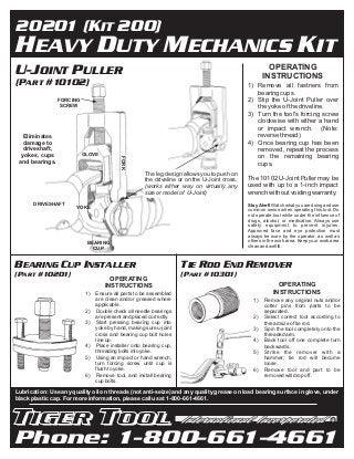
U-JOINT PULLER OPERATING
INSTRUCTIONS
(PART #10102) 1) Remove all fastners from
bearing cups.
FORCING 2) Slip the U-Joint Puller over
SCREW the yoke of the driveline.
3) Turn the tool's forcing screw
clockwise with either a hand
or impact wrench. (Note:
Eliminates reverse thread)
damage to 4) Once bearing cup has been
driveshaft, removed, repeat the process
yokes, cups GLOVE
on the remaining bearing
FORK
and bearings. cups.
The leg design allows you to push on
the driveline or on the U-Joint cross. The 10102 U-Joint Puller may be
(works either way on virtually any used with up to a 1-inch impact
size or model of U-Joint) wrench without voiding warranty.
DRIVESHAFT Stay Alert! Watch what you are doing and use
YOKE common sense when operating this tool. Do
not operate tool while under the influence of
drugs, alcohol, or medication. Always use
safety equipment to prevent injuries.
Approved face and eye protection must
always be worn by the operator, as well as
BEARING others in the work area. Keep your work area
clean and well lit.
CUP
BEARING CUP INSTALLER TIE ROD END REMOVER
(PART #10201) (PART #10301)
OPERATING
INSTRUCTIONS OPERATING
1) Ensure all parts to be assembled INSTRUCTIONS
are clean and/or greased where 1) Remove any original nuts and/or
applicable. cotter pins from parts to be
2) Double check all needle bearings separated.
are present and placed correctly. 2) Select correct tool according to
3) Start pressing bearing cup into thread size of tie rod.
yoke by hand, making sure u-joint 3) Spin the tool completely onto the
cross and bearing cup bolt holes threaded arm.
line up. 4) Back tool off one complete turn
4) Place installer onto bearing cup, backwards.
threading bolts into yoke. 5) Strike the remover with a
5) Using an impact or hand wrench, hammer; tie rod will become
turn forcing screw until cup is loose.
flush to yoke. 6) Remove tool and part to be
6) Remove tool, and install bearing removed will drop off.
cup bolts.
Lubrication: Use any quality oil on threads (not anti-seize) and any quality grease on load bearing surface in glove, under
black plastic cap. For more information, please call us at 1-800-661-4661.
R
Phone: 1-800-661-4661
2. 20201 (KIT 200)
HEAVY DUTY MECHANICS KIT
SLACK ADJUSTER PULLER
(PART #10406)
OPERATING INSTRUCTIONS
1) Remove Clevis from the end of the Slack Adjuster with the
Tiger Brake Clevis Pin Press (Part #10501). Stay Alert! Watch what you are doing and
2) With the forcing screw backed out, slip the puller onto the use common sense when operating this
tool. Do not operate tool while under the
Slack Adjuster. influence of drugs, alcohol, or
medication. Always use safety equipment
3) Turn the forcing screw by hand or with an impact wrench. to prevent injuries. Approved face and
4) Slack Adjuster will drop off when free. eye protection must always be worn by
the operator, as well as others in the work
Do not use over ½ inch impact wrench. Doing so will void area. Keep your work area clean a n d
warranty. well lit.
SLACK ADJUSTER PULLER
(PART #10407)
OPERATING INSTRUCTIONS
1) Remove Clevis from the end of the Slack Adjuster with the
Tiger Brake Clevis Pin Press (Part #10501).
2) With the forcing screw backed out, slip the puller onto the
Slack Adjuster.
3) Attach tool to Slack Adjuster through clevis hole and
tighten.
4) Turn the forcing screw by hand or with an impact wrench.
5) Slack Adjuster will drop off when free.
Do not use over ½ inch impact wrench. Doing so will void
warranty.
Lubrication: Use any quality oil on threads (not anti-seize) and any quality grease on load bearing surface in glove, under
black plastic cap. For more information, please call us at 1-800-661-4661.
R
Phone: 1-800-661-4661