KYL-200L wireless data transmission RF module for 2-3km
•
0 gefällt mir•783 views

By using RF Module to achieve wireless data transmission. Any question,welcome to contact Minerva Email: sales01@rf-data.com Skype:rf-data

Empfohlen
Weitere ähnliche Inhalte
Was ist angesagt?
Was ist angesagt? (20)
Ähnlich wie KYL-200L wireless data transmission RF module for 2-3km
Ähnlich wie KYL-200L wireless data transmission RF module for 2-3km (20)
Kürzlich hochgeladen
Kürzlich hochgeladen (20)
KYL-200L wireless data transmission RF module for 2-3km
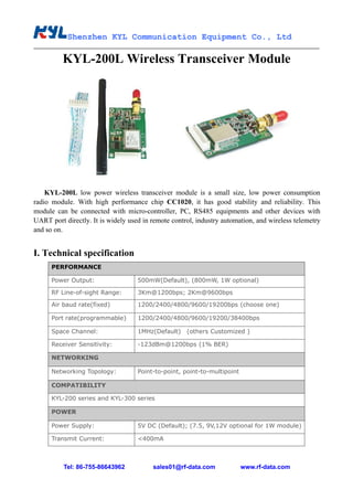
- 1. Shenzhen KYL Communication Equipment Co., Ltd Tel: 86-755-86643962 sales01@rf-data.com www.rf-data.com KYL-200L Wireless Transceiver Module KYL-200L low power wireless transceiver module is a small size, low power consumption radio module. With high performance chip CC1020, it has good stability and reliability. This module can be connected with micro-controller, PC, RS485 equipments and other devices with UART port directly. It is widely used in remote control, industry automation, and wireless telemetry and so on. I. Technical specification PERFORMANCE Power Output: 500mW(Default), (800mW, 1W optional) RF Line-of-sight Range: 3Km@1200bps; 2Km@9600bps Air baud rate(fixed) 1200/2400/4800/9600/19200bps (choose one) Port rate(programmable) 1200/2400/4800/9600/19200/38400bps Space Channel: 1MHz(Default) (others Customized ) Receiver Sensitivity: -123dBm@1200bps (1% BER) NETWORKING Networking Topology: Point-to-point, point-to-multipoint COMPATIBILITY KYL-200 series and KYL-300 series POWER Power Supply: 5V DC (Default); (7.5, 9V,12V optional for 1W module) Transmit Current: <400mA
- 2. Shenzhen KYL Communication Equipment Co., Ltd Tel: 86-755-86643962 sales01@rf-data.com www.rf-data.com Receive Current: <28mA Sleep current: <20uA GENERAL Communication Mode: Half-duplex Frequency Band: 433MHz (400/450/470MHz/868MHz/915MHz optional) Channel: 8(default),16/32/64(optional) Interface: TTL or RS232 or RS485 or USB PHYSICAL PROPERTIES Size: 53mm×38mm×10mm (excluding antenna base and data pin) Weight: 22g Antenna Base: 50Ω, SMA Operating Temperature: Industrial:-40℃~+80℃(TCXO) Frequency Stability: ±2.5ppm Industrial II. Application Field * Automatic Meter Reading (AMR); * Wireless alarm and security systems; * Building automation, security systems, wireless monitor; * Wireless data transmission, automatic data collection system; * Wireless POS, PDA wireless smart terminal; * RF transmitter, Wireless electronic display screen and Queuing machine; * Wireless telemetry; remote control and access control system; * Wireless modem automobile inspection and four-wheel orientation; * Wireless sensor, Industrial wireless remote control; * Data communication in the aspects of railway, oil field, dock and army. * LED display in thruway and public place; * Point to multi-point wireless network. ...... III. How to Use It
- 3. Shenzhen KYL Communication Equipment Co., Ltd Tel: 86-755-86643962 sales01@rf-data.com www.rf-data.com 1. Default 5V Power supply 2. PIN Definition (9pin) Pin No. Signal Name Function Level Connection with terminal Remarks 1 GND Grounding of power supply Ground 2 Vcc Power supply DC 5V 3 RxD/TTL Data receiving TTL TxD 4 TxD/TTL Data transmitting TTL RxD 5 SGND Signal 6 A (TXD) A of RS-485 (TxD of RS-232) A(RxD) 7 B (RXD) B of RS-485 (RxD of RS-232) B(TxD) 8 SLEEP Sleep control TTL Sleep signal Low level valid 9 RESET Factory testing TTL 3. The connection schematic between computer and the RF module 4. Installation dimension:
- 4. Shenzhen KYL Communication Equipment Co., Ltd Tel: 86-755-86643962 sales01@rf-data.com www.rf-data.com 5. The Function-indicator light a. The LED indicator blinks red for 0.5S when power on. b. The LED indicator turns green continually when receiving data. c. The LED indicator blinks red continually when transmitting data d. The LED indicator keeps dark when the module is in sleep mode. 6. Sleep function In order to reduce power consumption, KYL-200L transceivers support sleep function. In sleep mode, the current consumption is around 10uA. (need to specify when you place order) a. How to use sleep function: The Pin8 ‘SLP’ is sleep control pin. At high level, transceiver stays in working mode. At low level (<0.5V), transceiver stays in sleep mode. The SLP signal can convert transceiver from working to sleep mode in about 10mS after falling edge. If the Sleep signal arrives when the transceiver is transmitting data, the module will move to sleep mode after finishing transmission. From sleep to working, it takes about 10ms after rising edge. To disable the opened sleep function of KYL-200L, the SLP (SLEEP) pin should be connected with VCC or keep it no connection. b. Attentions about using sleep function: When the sleep function enabled, or any supply glitches, such as switch dithering, fire striking or quick switching on and off, may cause the transceiver switch to wrong sleep mode. After switching on, users can avoid this error by making a compulsive restoration once after the CPU delays 100ms. Sleep Timing Diagram: 7. Attentions about data transmission a. The delay time (tc) of conversion between transmitting and receiving is less than 1ms.
- 5. Shenzhen KYL Communication Equipment Co., Ltd Tel: 86-755-86643962 sales01@rf-data.com www.rf-data.com Timing diagram: b. The delay time of transceivers between the first bit sent by TxD to the first bit received by RxD. when RxD of a KYL-200L ‘A’ receives the data, then transmits it, the other KYL-200L ‘B’ will have a delay (ts) to receive and transmit by TxD. Different RF data rate causes different delay time. Please see the specific delay time below: RF Date Rate (bps) Delay Ts (mS) RF Date Rate (bps) Delay Ts (mS) 1200 90 9600 16 2400 48 19200 10 4800 30 Timing diagram: 8. Parameter setting by our software You can use our software KYLCOM.exe to read or set the parameter on computer. When you connect RF module to PC by the testing cable, please remember to connect the DB9 as well as USB port to computer.
- 6. Shenzhen KYL Communication Equipment Co., Ltd Tel: 86-755-86643962 sales01@rf-data.com www.rf-data.com Corresponding frequency for each channel: Channel No. Frequency Channel No. Frequency 1 429.0325MHZ 5 433.0325MHZ 2 430.0325MHZ 6 434.0325MHZ 3 431.0325MHZ 7 435.0325MHZ 4 432.0325MHZ 8 436.0325MHZ Note: Each channel has fixed frequency. You can change frequency via adjusting the channels. If you need special frequency point, please tell us when you place order. 9. About antenna We usually allocate KYL-200L RF module with the following antenna. If you have any special needs about the antenna, please specify. You are welcomed to visit our web for more choice about the antenna: http://www.rf-data.com/product2.asp?BigClassName=Antennas. Moreover, we also provide OEM&ODM service. A standard unit includes one module, one antenna and one 9-pin cable like the 1st picture. When you place order, please confirm what frequency, baud rate, and interface do you use. Air baud rate is fixed, interface baud rate is programmable. Any more questions, please contact and ask Minerva freely. Minerva Zhao Web: www.rf-data.com E-mail: sales01@rf-data.com Skype: rf-data MSN: KYL-Minerva@outlook.com Gmail: RF.Minerva828@gmail.com