Ship Construction (Structure Part)
•
210 likes•115,260 views

Ship Construction (Structure Part)

Recommended
More Related Content
What's hot
What's hot (20)
Viewers also liked
Viewers also liked (20)
Similar to Ship Construction (Structure Part)
Similar to Ship Construction (Structure Part) (20)
Recently uploaded
Recently uploaded (20)
Ship Construction (Structure Part)
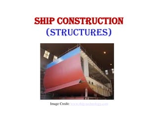
- 1. SHIP CONSTRUCTION (STRUCTURES) Image Credit: www.ship-technology.com
- 2. KEEL - At the centre line of the bottom structure is located the keel, which is often said to form the backbone of the ship. This contributes substantially to the longitudinal strength and effectively distributes local loading caused when docking the ship. Flat Plate Keel: - The commonest form of keel is that known as the ‘flat plate’ keel, and this is fitted in the majority of ocean-going and other vessels. Bar Keel - A form of keel found on smaller vessels is the bar keel . The bar keel may be fitted in trawlers, tugs etc., and is also found in smaller ferries. - Where grounding is possible this type of keel is suitable with its massive scantlings, but there is always a problem of the increased draft with no additional cargo capacity. If a double bottom is fitted the keel is almost inevitably of the flat plate type, bar keels often being associated with open floors, where the plate keel may also be fitted.
- 4. Duct Keel: - Duct keels are provided in the double bottoms of some vessels. These run from the forward engine room bulkhead to the collision bulkhead and are utilised to carry the double bottom piping. The piping is then accessible when cargo is loaded, an entrance to the duct being provided at the forward end of the engine room. - No duct is required aft of the engine room as the piping may be carried in the shaft tunnel.
- 7. Keel Plate: The hull requires a plate floor every 3.05m and a frame every 1m. Hence there are 3 frames for every plate floor. The two frames are attached to the floor angle iron transverse. For the aft framing of the aft peak tank or the for'd framing of the for'd collision bulkhead the maximum framing pitch is 0.61m. Also for the for'd 0.2l of the ship the maximum spacing of the frame is 700mm (this helps to prevent damage due to slamming). Underneath the engine seating a plate flooris required every frame. The keel plate is made from heavier section of plate and has its ends tapered to allow it to be welded onto the normal hull plating
- 9. Double Bottom Tank: An inner bottom (or tank top) may be provided at a minimum height above the bottom shell, and maintained watertight to the bilges. This provides a considerable margin of safety, since in the event of bottom shell damage only the double bottom space may be flooded. The space is not wasted but utilised to carry oil fuel and fresh water required for the ship, as well as providing ballast capacity. The minimum depth of the double bottom in a ship will depend on the classification society’s requirement for the depth of centre girder. It may be deeper to give the required capacities of oil fuel, fresh water, and water ballast to be carried in the bottom. Water ballast bottom tanks are commonly provided right forward and aft for trimming purposes and if necessary the depth of the double bottom may be increased in these regions. In way of the machinery spaces the double bottom depth is also increased to provide appreciable capacities of lubricating oil and fuel oil. The increase in height of the inner bottom is always by a gradual taper in the longitudinal direction, no sudden discontinuities in the structure being tolerated.
- 10. Double bottoms may be framed longitudinally or transversely , but where the ship’s length exceeds 120m it is considered desirable to adopt longitudinal framing. The explanation of this is that on longer ship tests and experience have shown that there is a tendency for the inner bottom and bottom shell to buckle if welded transverse framing is adopted. This buckling occurs as a result of the longitudinal bending of the hull, and may be avoided by having the plating longitudinally stiffened
- 14. FLOORS - Vertical transverse plate floors are provided both where the bottom is transversely and longitudinally framed. - At the ends of bottom tank spaces and under the main bulkheads, watertight or oiltight by closing any holes in the plate floor and welding collars around any members which pass through the floors. - Elsewhere ‘solid plate floors’ are fitted to strengthen the bottom transversely and support the inner bottom. These run transversely from the continuous centre girder to the bilge, and manholes provided. - Lightening holes are cut in each solid plate floor. Also small air and drain holes may be drilled at the top and bottom respectively of the solid plate floors in the tank spaces. - The spacing of the solid plate floors varies according to the loads supported and local stresses experienced. - At intermediate frame spaces between the solid plate floors, ‘bracket floors’ are fitted. The bracket floor consists simply of short transverse plate brackets fitted in way of the centre girder and tank sides (see Figures 10 and 11).
- 19. Bottom Structure of Bulk Carriers Where a ship is classed for the carriage of heavy, or ore, cargoes longitudinal framing is adopted for the double bottom. A closer spacing of solid plate floors is required, the maximum spacing being 2.5m and also additional intercostals side girders are provided, the spacing not exceeding 3.7m (see Figure 12). The double bottom will be somewhat deeper than in a conventional cargo ship, a considerable ballast capacity being required; and often a pipe tunnel is provided through this space. Inner bottom plating, floors, and girders all have substantial scantlings as a results of the heavier cargo weights to be supported.
- 21. Longitudinally framed hull (tanker) The longitudinal framing is much better able to resist buckling when the hull is hogging Source: www.marineengineering.org.uk
- 25. Longitudinal framing (Dry Cargo) Source: www.marineengineering.org.uk
- 30. The shell plating forms the watertight skin of the ship and at the same time, in merchant ship construction, contributes to the longitudinal strength and resists vertical shear forces. Internal strengthening of the shell plating may be both transverse and longitudinal and is designed to prevent collapse of the plated under the various loads to which it is subject The bottom and side shell plating consists of a series of flat and curved steel plates generally of greater length than breadth butt welded together. The vertical welded joints are referred to as ‘butts’ and the horizontal welded joints as ‘seams’ (see Figure 14). Stiffening members both longitudinal and transverse are generally welded to the shell by intermittent fillet welds with a length of continuous weld at the ends of the stiffening member. Continuous welding of stiffening members to the shell is found in the after peak, the bottom shell within the forward 30 percent of the length and where higher tensile steel is used. Framing is notched in way of welded plate butts and seams.
- 36. ADDITIONAL STIFFENING FOR PANTING Additional stiffening is provided in the fore peak structure, the transverse side framing being supported by any, or a combination of the following arrangements: a.Side stringers spaced vertically about 2m apart and supported by struts or beams fitted at alternate frames. These ‘panting beams’ are connected to the frames by brackets and if long may be supported the ships centre line by a partial wash bulkhead. Intermediate frames are bracketed to the stringer (see Figure 17). b.Side stringers spaced vertically about 2m apart and supported by web frames. c.Perforated flats spaced not more than 2.5m apart. The area of perforations being not less than 10 percent of the local area of the flat. Aft of the forepeak in the lower hold or deep tank spaces panting stringers are fitted in line with each stringer or perforated flat in the forepeak extending back over 15 percent of the ship length from forward.
- 41. Anchoring equipment The anchoring equipment fitted to the majority of vessels consists of two matched units, offering a degree of redundancy. These units consists of an anchor, chain (or for smaller vessels wire), a gypsum or chain lifter wheel, brake, lift motor and various chain stopper arrangements. When not in he use the chain is stowed in a chain locker, systems fitted with wire are stowed on a drum in the same way as winches.
- 43. Chain locker • A false bottom is fitted to the chain locker consisting of a perforated plate. This allows water and mud to be removed from the space. The end of the chain is attached to the hull by a quick release mechanism known as the 'bitter end'. • The strength of the 'Bitter End' fixing arrangement for a moderately large vessel is in the region of 6 Н tons, this will not be sufficient to prevent a run away unbraked chain. The arrangement must be easily accessible. • The proof load for the windlass (the load the windlass must withstand without being pulled from the deck) is given by; • 6.18 dc2 (44 + 0.08dc) [kN] • Where dc is the diameter of the chain metal . • This will prove that it is strong enough. It must also be as strong as the braking load on the cable. • The windlass must be capable of pulling the anchor from a depth of 25% of the total cable carried, i.e. 50% of the length of chain on one side • It should be capable of lifting the anchor from 82.5m to 27.5m at 9m/min
- 45. Hawser The chain is led overboard by a strengthened and reinforced pipe called a Hawser One of the reasons for bow flare is to allow the anchor and chain to lie well clear of the hull when in use, preventing damage.
- 47. Chain stopper • For anchoring operations the stopper bar is locked upright. When it is required to fix the position of the chain the stopper is lowered into the position shown. This allows the brake to be released and is typically used for stowing the anchor. chain stopper arrangements are not design to stop a runaway chain. Alternately an arrangement known as the 'devil's claw' may be used which has a forked locking piece. For smaller vessels, and where extra security is required bottle jacks with wire strops passed though the chain may be used.
- 48. Chain End pull will cause the link to collapse in. This repeated many times will lead to fatigue failure. Hence, stud linked chain is insisted upon Source: www.marineengineering.org.uk
- 50. Connecting chain and components • To join two sections of chain a 'kentish' (don't quote me on the name) shackle is used. This consists of two half sections and removable bridge all held together by a tapered pin. This arrangement works remarkably well and can be found on all sizes of chain.
- 54. Tank Side Brackets • The lower end of the frame may be connected to the tank top or hopper side tank by means of a flanged or edge stiffened tank side bracket as illustrated in Figure 16B.
- 62. Machinery Seats It has already been indicated that in the machinery spaces additional transverse floors and longitudinal intercostals side girders are provided to support the machinery effectively and to ensure rigidity of the structure. The main engine seatings are in general integral with this double bottom structure, and the inner bottom in way of the engine foundation has a substantially increased thickness. Often the machinery is built up on seatings forming longitudinal bearers which are supported transversely by tripping brackets in line with the double bottom floors, the longitudinal bearers being in line with the double bottom side girders. Boiler bearers are similarly fabricated with support from transverse brackets and longitudinal members
- 63. Fig: Engine Seating Source: www.marineengineering.org.uk
- 64. Flat Bed Plate • There are transverse plate floors at each frame. The thickness of the engine seating is governed by the power, weight, and length of the unit
- 65. Small Drop-raised Seat Large Drop-raised seat Source: www.marineengineering.org.uk
- 67. • Historically the engine bolts at the after end of the engine were fitted bolts to take the shear of the thrust and the more for'd bolts were loose fit bolts allowing for expansion. • This method has proved unreliable and the more modern practice is to weld lugs on the bedplate and have brackets and fitted chocks
- 69. Bedplate location • The holding down arrangement should be arranged to be above any bilge water level to allow for easy access and inspection
- 71. Engine Mounting for seperate thrust block • Where the thrust is taken in the gearbox casing it is necessary then to have the mounts for the casing as close as possible to the centreline of the shaft so as to ensure little or no bending moment on the casing. The mountings should be suitably extended in a similar fashion to the thrust block arrangement shown above
- 73. • Stern Frame • A stern frame may be cast or fabricated and its shape is influenced by the type of rudder being used and the profile of the stern. Sternframes also differ between twin and single screw ships, the single screw sternframe having a boss for the propeller shaft. Adequate clearance is essential between propeller blade tips and sternframe in order to minimise the risk of vibration. As blades rotate water immediately ahead of the blades is compressed and at the blade tips this compression can be transmitted to the hull in the form of a series of pulses which set up vibration. Adequate clearance is necessary or alternatively constant clearance, this being provided with ducted propellers such as the Kort nozzle. A rotating propeller exerts a varying force on the sternframe boss and this can result in the transmission of vibration. Rigid construction is necessary to avoid this. The stern post, of substantial section, is carried up inside the hull and opened into a palm end which connects to a floor plate, This stern post is often referred to as the vibration post as its aim is to impart rigidity and so minimise the risk of vibration. Side plating is generally provided with a Rabbet or recess in order that the plating may be fitted flush. The after most keel plate which connects with this region the structure od the ship serves no useful purpose and it is known as the 'deadwood'. This may be removed without ill effect on stability or performance and some sternframes are designed such that the deadwood is not present.
- 74. Shaped rudder Asymmetric hull Source: www.marineengineering.org.uk
- 75. As the wash of the propeller does not enter at the same angle rudders (sometimes called 'slopped') with uneven inlet angles are sometimes fitted to even the flow from the propeller. Another design involves the use of design. The water is directed in the same direction as the blade rotation and hence the shock loading occurring when the blade hits relatively still water is removed Increasing number of blades and skewing An overlap can be arranged to reduce the pressure fluctuations and change the forcing frequency
- 76. Consists of two half loops mounted either side of the hull which smooths the flow of water into the propeller Source: www.marineengineering.org.uk
- 78. The advantages of mounting drive shafts externally are: - Reduced 'blade passing' hull vibration and noise - Increase propeller effcicency as hull in clearer water - Allows finer stern hull form increaseing hull efficiency and reducing material requirements - Some disadvantages are - Propshaft is more open to damage, erosion and corrosion, for some desgins the extended length of the shaft is shrouded. Increase hull drag
- 79. Welded construction Source: www.marineengineering.org.uk
- 81. Vertically mounted watertight door Source: www.marineengineering.org.uk
- 82. Water Tight Doors: To allow the passage for personnel water tight doors are fitted , openings must be cut only were essential and they should be as small as possible. 1.4m high, 0.7m wide being the usual. Doors should be of mild steel or cast steel, and they may be arranged to close vertically or horizontally. The closing action must be positive i.e. it must not rely on gravity. Hinged water tight doors may be allowed in passenger ships and in watertight bulkheads above decks which are placed 2.2m or more above the waterline. Similar doors may be fitted in weather decks openings in cargo ships
- 83. Hinged water tight door Source: www.marineengineering.org.uk
- 84. Hinged water tight doors consist of a heavy section door which when closed seals on a resilient packing mounted in channel bar welded to the door frame. The door is held firmly in the door frame when closed by the dogging arrangements shown which allow the doors to be opened from either side. Normally six of these dogs are spread equally around the periphery.
- 85. Automatic watertight operating gear Source: www.marineengineering.org.uk
- 86. Operating of Water Tight Doors: Automatic operating gear allows the remote operation of watertight doors. These are fitted on many vessels including passenger ships. In the event of fire or flooding, operation of switches from bridge/fire control area sends a signal to an oil diverter valve. Oil from a pressurised hydraulic system is sent to a ram moving the door. The door may also be operated locally by a manual diverter valve. In addition, in the event of loss of system pressure the door may be operated by a local manual hand pump remote door position indicators are fitted as well as were appropriate alarms to indicate operation
- 87. Bulkhead definitions Class A Class A divisions are forming bulkheads and decks that; •Constructed of steel or equivalent •suitably stiffened •Prevent passage of smoke and flame to the end of one hour standard fire test •Insulated using non-combustible material so that average temperature on exposed side does not rise above 140oC and point temperature above 180oC. The time the bulkhead complies with this governs its class A-60 60min A-30 30Min A-15 15Min A-0 0Min
- 88. Class B - These are divisions formed by bulkheads, decks, ceilings and lining Prevent passage of flame for first half hour of standard fire test Insulated so average exposed side temperature does not rise more than 139oC above original and no single point rises more than 225oC above original. - The time the bulkhead complies with this governs its class: B-15 15Min B-0 0Min Constructed of non-combustible material and all materials entering the construction are similarly non-combustible except where permitted Class C - These are divisions constructed of approved non-combustible materials. Combustible veneers are allowed were they meet other criteria. - Main vertical zones Divided by Class A bulkheads and not exceeding 40m in length
- 89. Bulkheads There are three basic types of bulkhead, watertight, non watertight and tank. Different types of bulkheads are designed to carry out different functions. The watertight bulkhead several important ones; 1. It divides the ship into watertight compartments giving a buoyancy reserve in the event of hull being breached. The number of compartments is governed by regulation and type of vessel 2. cargo separation 3. They restrict the passage of flame 4. Increased transverse strength, in effect they act like ends of a box 5. Longitudinal deck girders and deck longitudinal are supported by transverse watertight bulkheads which act as pillars
- 91. Types of Bulk Head: There are three basic types of bulkhead, watertight, non watertight and tank. Different types of bulkheads are designed to carry out different functions. The watertight bulkhead several important ones; It divides the ship into watertight compartments giving a buoyancy reserve in the event of hull being breached. The number of compartments is governed by regulation and type of vessel: - Cargo separation. - They restrict the passage of flame - Increased transverse strength, in effect they act like ends of a box - Longitudinal deck girders and deck longitudinal are supported by transverse watertight bulkheads which act as pillars
- 93. Test of water tight bulkheads: - Watertight bulkheads must be tested with a hose at a pressure of 200 Kn/m2 . The test being carried out from the side on which the stiffeners are fitted and the bulkhead must remain watertight. - Water tight bulkheads which are penetrated by pipes, cables etc. must be provided with suitable glands which prevent the passage of water.
- 94. Prefabrication Rather than plan outfit installation on a total ship system basis, it is today common practice to plan this work for zone installation, the zone corresponding to a main compartment area which may e broken down into blocks or smaller assemblies. Pre-outfitting of each assembly or block may be or the order of 85-90 percent. Both steelwork and outfit are highly planned for each assembly and block unit, and fabrication and outfit installation is undertaken at a work station where the facilities and material are supplied.
- 96. Sub-Assemblies When plates and sections have been machined they are ready for assembly into ship units. Within the fabrications shop there are often arranged a number of bays for different assemblies, for example flat plate panels, curved shell units, matrix or ‘egg box’ structures and some minor sub-assemblies. All these may be termed sub-assemblies if they are subsequently to be built into a large unit prior to erection. Panel assembly is usually highly automated with prepared plates being placed and tack welded prior to automatic welding of the butts, after which the plates are turned and back welded unless a single sided weld process has been used. The panel is marked and the stiffeners placed and welded automatically or with semi-automatic process. Minor sub-assemblies such as deep frames consisting of web and welded face flat may also be attached at this stage. Curved shell plates are placed on jigs and welded and the various stiffening members can be aligned and welded in a similar manner to those on a flat panel assembly. Assembly jigs may also be used for matrix or ‘egg box’ assemblies, for example structures of solid and bracket plate floors with longitudinal side girders which are to go into double bottom units.
- 97. Unit Fabrication In most instances the 2-dimensional sub-assemblies will be built into 3- dimensional block assemblies. The size of the block assembly will have been decided at an early stage of the planning process ideally at the structural design stage. Constraints such as lifting capacities and dimensions that can be handed are taken into consideration also the provision of breaks at natural features ensuring the block are self supporting and easily accessed etc. Panel assemblies used in the block may well have dimensions restricted by the plate length that can be handled at the machining stage and this can subsequently influence block length. In the machinery area the block size and arrangements can be decided by zone outfit considerations. Each block should be designed for maximum downhand welding but may have to be turned for this purpose. Also block are turned to effect outfit installation particularly those containing machinery flats in the aft engine room areas where pipework etc. can be fitted on the underside of the flat with the block in the inverted position and then it is turned to install equipment above the flat . A block’s centre of gravity is calculated and lifting lugs so provided that these operations can be undertaken, and finally the block can be suspended for erection at the building dock or berth and drop into place in the correct plane.
- 98. OUTFIT MODULES Units of machinery, pipework and other outfit systems required for a specific zone can be planned and built up into modules and installed as such into a block fabrication. Pipework in particular lends itself to this form of assembly and can, with careful planning from the CAD stage, be arranged in groupings so that pipe bank modules can be arranged for a particular zone. Modules can range from a small pipe bank supported by light framing of pipe hangers, or a complete auxiliary machinery unit on its seating which has even been test run prior to installation, to a large modular unit which together with several similar units constitutes the bulk of a complete engine room. Not all outfits can be incorporated into modules and a large number of piece parts have to be provided for fitting in any given zone at a particular time within the assembly shops. To maintain production engineering standards a concept of ‘palletisation’ has been developed whereby the piece parts for that zone are generated at the CAD/CAM stage, bought in and/or fabricated etc. and made available at the work station when the particular assembly is ready to receive them.
- 99. An ‘open top’ arrangement for block or smaller ships being outfitted under cover can facilitate installation of the items and modules. Superstructure blocks are fabricated separately and pre-outfitted with accommodation before erection as a complete unit. Modular cabin units are a common feature of modern shipbuilding, Figure below shows a typical self supporting cabin/toilet module complete with pipework, ventilation, electrical fittings, wiring, and all built-in furniture
- 101. Experience of previous ship erection schedules and difficulties given the yard’s physical and equipment constraints leads to standard practices being established. These are taken into consideration at the structural design stage as are the desirability of minimising positional welding and fairing. In general it is common practice to make a start in the region of the machinery spaces aft, working from the bottom upwards, and also forward and aft, this area requires larger amount of finishing work. In particular the boring of the stern for the tail shaft is preferably undertaken when the after sections are fully faired and welded.
- 102. In erecting the ship units it is important to employ the correct welding sequences. These are arranged to avoid excessive ‘locked in’ stresses; and overlapping frames, longitudinals, stiffeners etc. may be left unwelded across unit seams and butts until these are completed. In erecting units, tolerances are a problem, more so on 3-dimensional units than with 2-dimensional units and particularly at the shaped ends of the ship. Quality control procedures in the manufacturing shops to ensure correct dimensioning and alignment are very necessary if time- consuming, expensive and arduous work at the berth is to be avoided. Improvements in this area have been made with the use of accurate jigs for curved shell units, planned weld sequences, and use of lower heat input welding equipment dimensional checks on piece parts, and the use of laser alignment tools for setting up datums and checking interfaces.
- 103. Joining Ship Sections Afloat Owing to the enormous increase in size of bulk carriers and tankers, shipyards with restricted facilities, berth size particularly, have examined various means of building these large ships in sections which are to be joined off the berth.In most cases the problem becomes one of joining the two hull sections afloat or in a dry-dock of sufficient size where available. Where the sections are to be joined afloat, extremely accurate fit up of the sections is aided by the possibilities of ballasting the two ship halves. The two sections may then be pulled together by tackles; and for the finer adjustments hydraulic cylinders may be used, extremely accurate optical instruments being employed to mark off the sections for alignment. One method adopted is that where a cofferdam is arranged in way of the joint, a caisson is brought up against the ship’s hull, and the cofferdam and caisson are pumped dry. To balance any tendency for the vessel to ‘hog’ during the pumping of the cofferdam it is necessary to shift ballast in the fore and aft sections. Once the spaces are dried out welding of the complete joint may be undertaken, the resulting weld being X-rayed to test the soundness of such a critical joint. On completion of the paint scheme in way of the joining the caisson is removed.
- 106. References 1. Ship Construction DJ Eyres & GJ Bruce 2. Ship Construction Sketches and Notes-KEMP & YOUNG 3. www.marineengineering.org.uk/page81 4. Merchant Navy http://www.merchantnavy.com 5. Warsash Nautical Bookshop http://www.nauticalbooks.co.uk 6. Classification Societies http://www.iacs.org.uk 7. Lloyds Register http://www.lr.org 8. IMO http://www.imo.org
Editor's Notes
- From here marineeng.org