Bai giang-uml-25-27feb14
•Als PPTX, PDF herunterladen•
0 gefällt mir•653 views

Bài giảng UML cho lớp 55PM1, Khoa Công nghệ thông tin, Đại học Xây Dựng Hà nội, ngày 25 & 27 tháng 02 năm 2014

Empfohlen
Weitere ähnliche Inhalte
Ähnlich wie Bai giang-uml-25-27feb14
Ähnlich wie Bai giang-uml-25-27feb14 (20)
Mehr von TRAN Khanh Dung, Khoa CNTT, Đại Học Xây Dựng
Mehr von TRAN Khanh Dung, Khoa CNTT, Đại Học Xây Dựng (20)
Kürzlich hochgeladen
Kürzlich hochgeladen (20)
Bai giang-uml-25-27feb14
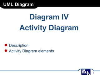
- 1. UML Diagram Diagram IV Activity Diagram ● Description ● Activity Diagram elements 1
- 2. Activity Diagram ● Activity diagram captures the dynamic behaviour of the system. ● An activity diagram is a connected oriented graph made of activity nodes and activity edges connecting a pair of activity nodes. ● The flow of control is drawn from one operation to another. This flow can be sequential, branched, concurrent, parallel, or single. 2
- 3. Activity Diagram ● Elements ● Initial node ● An initial node is a control node at which flow starts when the activity is invoked. An activity may have more than one initial node. ● Notation: 3
- 4. Activity Diagram ● Elements ● Final nodes ● An activity may have more than one activity final node. The first one reached stops all flows in the activity. ● Notation: 4
- 5. Activity Diagram ● Elements ● Action nodes ● An action node describe what will be done in the process modelled by the activity diagram. ● Notation: Action is shown as a round-cornered rectangle with action name in the center. 5
- 6. Activity Diagram ● Elements ● Activity ● An activity specifies the coordination of executions of subordinate behaviors that are modeled as activity nodes connected by activity edges. An activity may include flow of control constructs (e.g., decision, merge nodes, etc.,). ● Notation: Activity is shown as a round-cornered rectangle with activity name in the upper left corner and nodes and edges of the activity inside the border. 6
- 7. Activity Diagram ● Elements ● Object nodes ● An object node is an activity node that indicates an instance of a particular classifier, possibly in a particular state, may be available at a particular point in the activity. ● Notation: 7
- 8. Activity Diagram ● Elements ● Control flow edges ● A control flow edge connects two nodes and depicts the flowing of a control token from the first to the latter. The action nodes may have any number of ingoing and outgoing control flow edges, whereas the initial nodes may have only outgoing edges and the final nodes only ingoing edges. ● Notation: 8
- 9. Activity Diagram ● Elements ● Control flow edges ● A control flow edge connects two nodes and depicts the flowing of a control token from the first to the latter. The action nodes may have any number of ingoing and outgoing control flow edges, whereas the initial nodes may have only outgoing edges and the final nodes only ingoing edges. ● Notation: 9
- 10. Activity Diagram ● Elements ● Decision nodes ● A decision node accepts tokens on an incoming edge and presents them to multiple outgoing edges. Which of the edges is actually traversed depends on the evaluation of the guards on the outgoing edges. ● Notation: 10
- 11. Activity Diagram ● Elements ● Merge node ● A merge node is a control node that bring together multiple alternate flows. It is not used to synchronize concurrent flows but to accept one among several alternate flows. A merge node has multiple incoming edges and a single outgoing edge. ● Notation: 11
- 12. Activity Diagram ● Elements ● Fork nodes ● A fork node is a control node that splits a flow into multiple concurrent flows. A fork node has one incoming edge and multiple outgoing edges. ● Notation: 12
- 13. Activity Diagram ● Elements ● Join nodes ● A join node is a control node that synchronizes multiple flows. A join node has multiple incoming edges and one outgoing edge. ● Notation: 13
- 14. Activity Diagram ● Elements ● Activity partition (Swimlane) ● An activity partition is a kind of activity group for identifying actions that have some characteristic in common. ● Notation: Activity partition is indicated with parallel lines, (horizontal or vertical), a name labeling the partition in a box at one end. Any activity nodes and edges placed between these lines are considered to be contained within the partition. 14