SlideShare ist ein Scribd-Unternehmen logo
1 von 1
Downloaden Sie, um offline zu lesen
Calculation for W10x30 A36 Beam with
Concentrated Load at Center (ASD Method)
Engineering Analysis
by Kevin Wilson
Conforms to Standards of AISC Steel
Construction Manual 8th Edition
Modulus of Elasticity of Steel: E 29000000psi:=
Yield Strength of A36: Fy 36ksi:=
Concentrated Load on Beam: P 5kip:=
Beam Span: l 120in:=
Properties of the W10x30 Beam Section:
Depth of Section: d 10.5in:=
Thickness of Web: tw 0.300in:=
Moment of Inertia: I 170in
4
:=
Section Modulus (X-Axis): Sx 32.4in
3
:=
Beam Loading Calculations:
Support Reactions: R
P
2
2.5 kip⋅=:= Maximum Shear: VMax R 2.5 kip⋅=:=
_________________________________________________________________________________________________
Shear Stress Check AISC Steel Manual 8th Ed., Section 1.5.1.2:
Allowable Shear Stress: Fv 0.40 Fy⋅ 14.4 ksi⋅=:= (Ref. AISC 8th Ed., Sect. 1.5.1.2.1)
Area in Shear: Av d tw⋅
2
3
⎛
⎜
⎝
⎞
⎟
⎠
⋅ 2.1in
2
=:=
Maximum Shear Stress: fv
VMax
Av
1.19 ksi⋅=:= < Fv 14.4 ksi⋅= OK
_________________________________________________________________________________________________
Bending Stress Check AISC Steel Manual 8th Ed., Section 1.5.1.2:
Allowable Bending Stress: Fb 0.60 Fy⋅ 21.6 ksi⋅=:= (Ref. AISC 8th Ed., Sect. 1.5.1.2.1)
Maximum Bending Moment: Mmax
P l⋅
4
150 kip in⋅⋅=:=
Bending Stress: fb
Mmax
Sx
4.63 ksi=:= Fb 21.6 ksi⋅= OK<
__________________________________________________________________________________________________
Deflection Check:
Allowable Deflection: Δallow
l
360
0.333 in=:=
Max. Deflection: Δmax
P l
3
⋅
48 E⋅ I⋅
⎛
⎜
⎝
⎞
⎟
⎠
0.037 in=:= < Δallow 0.333 in= OK

Weitere ähnliche Inhalte

Mehr von Kevin Wilson

03B-2AFW-V207_Rev002
03B-2AFW-V207_Rev00203B-2AFW-V207_Rev002
03B-2AFW-V207_Rev002Kevin Wilson
 
Exploded_View_Reedy_Motor3
Exploded_View_Reedy_Motor3Exploded_View_Reedy_Motor3
Exploded_View_Reedy_Motor3Kevin Wilson
 
Aux_Bldg_Cover_Load_Capacity
Aux_Bldg_Cover_Load_CapacityAux_Bldg_Cover_Load_Capacity
Aux_Bldg_Cover_Load_CapacityKevin Wilson
 
SI71_Grating_Capacity_Turbine_Bldg
SI71_Grating_Capacity_Turbine_BldgSI71_Grating_Capacity_Turbine_Bldg
SI71_Grating_Capacity_Turbine_BldgKevin Wilson
 
SI58_SKETCHES_EVAL
SI58_SKETCHES_EVALSI58_SKETCHES_EVAL
SI58_SKETCHES_EVALKevin Wilson
 
SI33_Jet_Impingement_Shield_Sketches
SI33_Jet_Impingement_Shield_SketchesSI33_Jet_Impingement_Shield_Sketches
SI33_Jet_Impingement_Shield_SketchesKevin Wilson
 
Safety_Trailer_Addition
Safety_Trailer_AdditionSafety_Trailer_Addition
Safety_Trailer_AdditionKevin Wilson
 
Kelly_Building_Sketches
Kelly_Building_SketchesKelly_Building_Sketches
Kelly_Building_SketchesKevin Wilson
 
U2_OUTAGE_BLDG_7-16-15
U2_OUTAGE_BLDG_7-16-15U2_OUTAGE_BLDG_7-16-15
U2_OUTAGE_BLDG_7-16-15Kevin Wilson
 
Calculation_Tubelock_Load_Capacity
Calculation_Tubelock_Load_CapacityCalculation_Tubelock_Load_Capacity
Calculation_Tubelock_Load_CapacityKevin Wilson
 
SI63_Hanger_Bracket_Evaluation
SI63_Hanger_Bracket_EvaluationSI63_Hanger_Bracket_Evaluation
SI63_Hanger_Bracket_EvaluationKevin Wilson
 
SI33_Evaluation_Temp_Support_Jet_Imping
SI33_Evaluation_Temp_Support_Jet_ImpingSI33_Evaluation_Temp_Support_Jet_Imping
SI33_Evaluation_Temp_Support_Jet_ImpingKevin Wilson
 

Mehr von Kevin Wilson (18)

03B-2AFW-V207_Rev002
03B-2AFW-V207_Rev00203B-2AFW-V207_Rev002
03B-2AFW-V207_Rev002
 
2-62A-809_Rev002
2-62A-809_Rev0022-62A-809_Rev002
2-62A-809_Rev002
 
2-01A-312_Rev002
2-01A-312_Rev0022-01A-312_Rev002
2-01A-312_Rev002
 
Exploded_View_Reedy_Motor3
Exploded_View_Reedy_Motor3Exploded_View_Reedy_Motor3
Exploded_View_Reedy_Motor3
 
JD317-01-Pack
JD317-01-PackJD317-01-Pack
JD317-01-Pack
 
Aux_Bldg_Cover_Load_Capacity
Aux_Bldg_Cover_Load_CapacityAux_Bldg_Cover_Load_Capacity
Aux_Bldg_Cover_Load_Capacity
 
SI71_Grating_Capacity_Turbine_Bldg
SI71_Grating_Capacity_Turbine_BldgSI71_Grating_Capacity_Turbine_Bldg
SI71_Grating_Capacity_Turbine_Bldg
 
SI58_SKETCHES_EVAL
SI58_SKETCHES_EVALSI58_SKETCHES_EVAL
SI58_SKETCHES_EVAL
 
SI51_PACK
SI51_PACKSI51_PACK
SI51_PACK
 
SI33_Jet_Impingement_Shield_Sketches
SI33_Jet_Impingement_Shield_SketchesSI33_Jet_Impingement_Shield_Sketches
SI33_Jet_Impingement_Shield_Sketches
 
Safety_Trailer_Addition
Safety_Trailer_AdditionSafety_Trailer_Addition
Safety_Trailer_Addition
 
Kelly_Building_Sketches
Kelly_Building_SketchesKelly_Building_Sketches
Kelly_Building_Sketches
 
SK-FE038_DWG_PACK
SK-FE038_DWG_PACKSK-FE038_DWG_PACK
SK-FE038_DWG_PACK
 
U2_OUTAGE_BLDG_7-16-15
U2_OUTAGE_BLDG_7-16-15U2_OUTAGE_BLDG_7-16-15
U2_OUTAGE_BLDG_7-16-15
 
Calculation_Tubelock_Load_Capacity
Calculation_Tubelock_Load_CapacityCalculation_Tubelock_Load_Capacity
Calculation_Tubelock_Load_Capacity
 
SI63_Hanger_Bracket_Evaluation
SI63_Hanger_Bracket_EvaluationSI63_Hanger_Bracket_Evaluation
SI63_Hanger_Bracket_Evaluation
 
SI33_Evaluation_Temp_Support_Jet_Imping
SI33_Evaluation_Temp_Support_Jet_ImpingSI33_Evaluation_Temp_Support_Jet_Imping
SI33_Evaluation_Temp_Support_Jet_Imping
 
S1
S1S1
S1
 

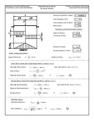
Beam7_Calculation_AISC_8thed

  • 1. Calculation for W10x30 A36 Beam with Concentrated Load at Center (ASD Method) Engineering Analysis by Kevin Wilson Conforms to Standards of AISC Steel Construction Manual 8th Edition Modulus of Elasticity of Steel: E 29000000psi:= Yield Strength of A36: Fy 36ksi:= Concentrated Load on Beam: P 5kip:= Beam Span: l 120in:= Properties of the W10x30 Beam Section: Depth of Section: d 10.5in:= Thickness of Web: tw 0.300in:= Moment of Inertia: I 170in 4 := Section Modulus (X-Axis): Sx 32.4in 3 := Beam Loading Calculations: Support Reactions: R P 2 2.5 kip⋅=:= Maximum Shear: VMax R 2.5 kip⋅=:= _________________________________________________________________________________________________ Shear Stress Check AISC Steel Manual 8th Ed., Section 1.5.1.2: Allowable Shear Stress: Fv 0.40 Fy⋅ 14.4 ksi⋅=:= (Ref. AISC 8th Ed., Sect. 1.5.1.2.1) Area in Shear: Av d tw⋅ 2 3 ⎛ ⎜ ⎝ ⎞ ⎟ ⎠ ⋅ 2.1in 2 =:= Maximum Shear Stress: fv VMax Av 1.19 ksi⋅=:= < Fv 14.4 ksi⋅= OK _________________________________________________________________________________________________ Bending Stress Check AISC Steel Manual 8th Ed., Section 1.5.1.2: Allowable Bending Stress: Fb 0.60 Fy⋅ 21.6 ksi⋅=:= (Ref. AISC 8th Ed., Sect. 1.5.1.2.1) Maximum Bending Moment: Mmax P l⋅ 4 150 kip in⋅⋅=:= Bending Stress: fb Mmax Sx 4.63 ksi=:= Fb 21.6 ksi⋅= OK< __________________________________________________________________________________________________ Deflection Check: Allowable Deflection: Δallow l 360 0.333 in=:= Max. Deflection: Δmax P l 3 ⋅ 48 E⋅ I⋅ ⎛ ⎜ ⎝ ⎞ ⎟ ⎠ 0.037 in=:= < Δallow 0.333 in= OK