
Empfohlen
Weitere ähnliche Inhalte
Kürzlich hochgeladen
Kürzlich hochgeladen (20)
Empfohlen
Empfohlen (20)
Calibre Wiring Guide
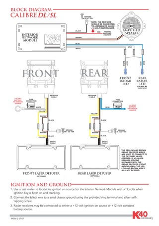
- 1. BLOCK DIAGRAM CALIBRE GROUND #8 X 1/2" TEK *NOTE: THE RED WIRE SHOULD BE CONNECTED TO A MINIMUM 16 GAUGE +12 VOLT IGNITION WIRE. BLACK RED IGNITION AMPLIFIED SWITCHED SPEAKER INTERIOR +12 VOLTS NETWORK BROWN MODULE BLUE GRAY WHITE WHITE BLUE GRAY GRAY FRONT REAR FRONT REAR RADAR RADAR LED LED (CALIBRE DL model only) RECEIVER RECEIVER CABLE CABLE +12 VOLT BATTERY FUSE FUSE CONNECTION CONNECTION OR IGNITION SOURCE +12 VOLT 1AMP WHITE BLUE 1AMP BATTERY OR IGNITION SOURCE YELLOW* YELLOW* BROWN* BROWN* BLACK BLACK GROUND GROUND #8 X 1/2" TEK #8 X 1/2" TEK BROWN* BROWN* BLACK BLACK YELLOW* YELLOW* BLACK BLACK CABLE CABLE *THE YELLOW AND BROWN RADAR RECEIVER WIRES ARE USED TO CONNECT TO THE OPTIONAL LASER DEFUSER. IF NO LASER DEFUSER IS BEING INSTALLED WITH THE RADAR RECEIVER (FRONT AND/OR REAR), THE YEL- LOW AND BROWN WIRES WILL NOT BE USED. FRONT LASER DEFUSER REAR LASER DEFUSER (OPTIONAL) (OPTIONAL) IGNITION AND GROUND 1. Use a test meter to locate an ignition on source for the Interior Network Module with +12 volts when ignition key is both on and cranking. 2. Connect the black wire to a solid chassis ground using the provided ring terminal and silver self- tapping screw. 3. Radar receivers may be connected to either a +12 volt ignition on source or +12 volt constant battery source. 44586-2 07/07
- 2. BLOCK DIAGRAM CALIBRE GROUND #8 X 1/2" TEK *NOTE: THE RED WIRE SHOULD BE CONNECTED TO A MINIMUM 16 GAUGE +12 VOLT IGNITION WIRE. BLACK AMPLIFIED RED IGNITION SWITCHED SPEAKER INTERIOR +12 VOLTS NETWORK BROWN MODULE BLUE GRAY WHITE WHITE BLUE GRAY GRAY FRONT REAR FRONT REAR RADAR RADAR RECEIVER RECEIVER pod pod CABLE CABLE (CALIBRE DL-P +12 VOLT model only) BATTERY FUSE FUSE CONNECTION CONNECTION OR IGNITION SOURCE +12 VOLT 1AMP WHITE BLUE 1AMP BATTERY OR IGNITION SOURCE YELLOW* YELLOW* BROWN* BROWN* BLACK BLACK GROUND GROUND #8 X 1/2" TEK #8 X 1/2" TEK BROWN* BROWN* BLACK BLACK YELLOW* YELLOW* BLACK BLACK CABLE CABLE *THE YELLOW AND BROWN RADAR RECEIVER WIRES ARE USED TO CONNECT TO THE OPTIONAL LASER DEFUSER(S). IF A LASER DEFUSER IS NOT BEING INSTALLED WITH A RADAR RECEIVER (FRONT AND/OR REAR), THE YELLOW AND BROWN WIRES WILL NOT BE USED. FRONT LASER DEFUSER REAR LASER DEFUSER (OPTIONAL) (OPTIONAL) IGNITION AND GROUND 1. Use a test meter to locate an ignition on source for the Interior Network Module with +12 volts when ignition key is both on and cranking. 2. Connect the black wire to a solid chassis ground using the provided ring terminal and silver self- tapping screw. 3. Radar receivers may be connected to either a +12 volt ignition on source or +12 volt constant battery source.